- Table of Contents
-
- 27-WLAN Configuration Guide (AC)
- 00-Preface
- 01-Compatibility of hardware and AC functionality
- 02-AP management configuration
- 03-Radio management configuration
- 04-WLAN access configuration
- 05-WLAN security configuration
- 06-WIPS configuration
- 07-WLAN QoS configuration
- 08-WLAN roaming configuration
- 09-WLAN load balancing configuration
- 10-WLAN radio resource measurement configuration
- 11-Channel scanning configuration
- 12-Band navigation configuration
- 13-WLAN high availability configuration
- 14-Wireless location configuration
- 15-WLAN multicast optimization configuration
- 16-User isolation configuration
- 17-WLAN probe configuration
- 18-Spectrum management configuration
- 19-WLAN optimization configuration
- 20-WLAN RRM configuration
- 21-WLAN IP snooping configuration
- 22-WLAN radio load balancing configuration
- 23-Client roaming center configuration
- Related Documents
-
| Title | Size | Download |
|---|---|---|
| 13-WLAN high availability configuration | 281.40 KB |
Restrictions and guidelines: Dual-link backup configuration
Dual-link backup tasks at a glance
Setting AP connection priority and specifying a backup AC
Configuring master CAPWAP tunnel preemption
Verifying and maintaining WLAN VSRP
Displaying information about clients kept online by client persistence
Clearing clients kept online by client persistence
Dual-link backup configuration examples
Example: Configuring dual-link backup
Restrictions and guidelines: Client backup configuration
Prerequisites for client backup
Setting the client backup delay
Display and maintenance commands for client backup
Restrictions and guidelines: WLAN VSRP
Associating the AC with a VSRP instance
Specifying the TCP port number for establishing a wireless client backup data channel
Triggering a manual switchback for a VRRP group
Verifying and maintaining WLAN VSRP
WLAN VSRP configuration examples
Example: Configuring WLAN VSRP
Example: Configuring manually-triggered preemption in an IPv4 VRRP group
Configuring dual-link backup
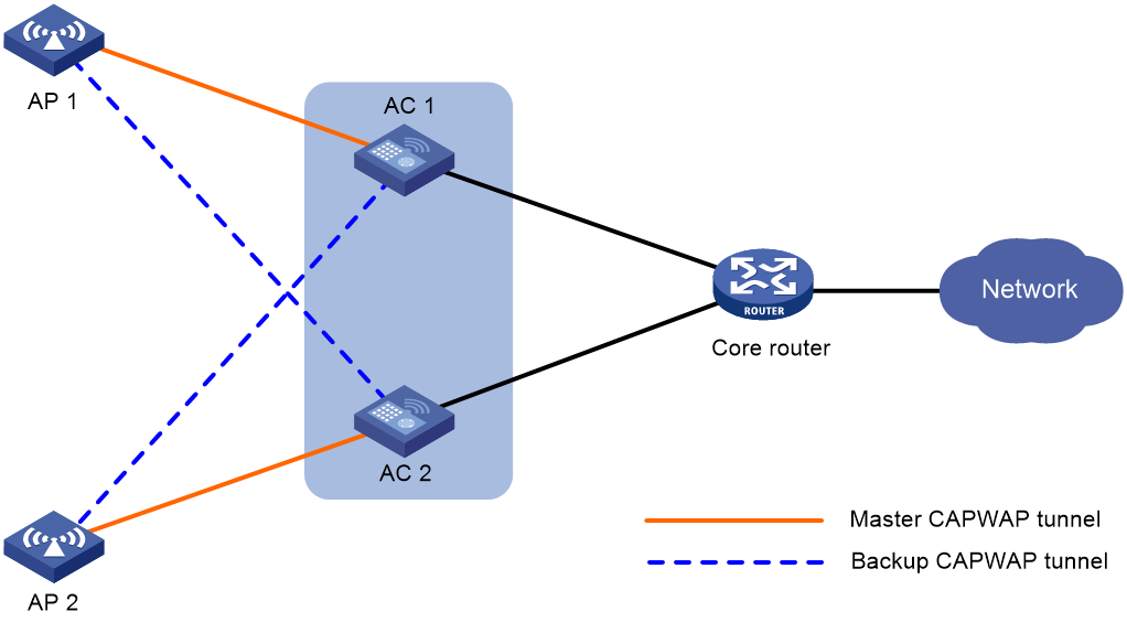
About dual-link backup
Dual-link backup enables two ACs to back up each other to reduce risks of service interruption caused by single-AC failures.
Dual-link backup is applicable to networks that are service continuity insensitive.
Figure 1 Network diagram for dual-link backup
Restrictions and guidelines: Dual-link backup configuration
For the dual-link backup feature to function correctly, configure auto AP or manual APs on the two ACs. The manual AP configuration must be identical on both ACs. For more information, see "Managing APs."
You can configure APs by using the following methods:
· Configure APs one by one in AP view.
· Assign APs to an AP group and configure the AP group in AP group view.
· Configure all APs in global configuration view.
For an AP, the settings made in these views for the same parameter take effect in descending order of AP view, AP group view, and global configuration view.
Dual-link backup tasks at a glance
To configure dual-link backup, perform the following tasks:
1. Setting AP connection priority and specifying a backup AC
2. (Optional.) Configuring master CAPWAP tunnel preemption
3. (Optional.) Enabling client persistence
Setting AP connection priority and specifying a backup AC
About this task
Set a higher AP connection priority for the master AC to ensure that APs can associate with the master AC first.
After an AP establishes a CAPWAP tunnel with the master AC, the AP will establish a backup CAPWAP tunnel with the specified backup AC.
Procedure
1. Enter system view.
system-view
2. Enter AP view or AP group view.
¡ Enter AP view.
wlan ap ap-name
¡ Enter AP group view.
wlan ap-group group-name
3. Set the AP connection priority.
priority priority
By default:
¡ In AP view, an AP uses the configuration in AP group view.
¡ In AP group view, the AP connection priority is 4.
4. Specify a backup AC.
backup-ac { ip ipv4-address | ipv6 ipv6-address }
By default:
¡ In AP view, an AP uses the configuration in AP group view.
¡ In AP group view, no backup AC is specified.
Configuring master CAPWAP tunnel preemption
About this task
This feature enables a backup CAPWAP tunnel to become a master tunnel after 10 minutes if the backup AC has higher AP connection priority than the master AC.
Procedure
1. Enter system view.
system-view
2. Enter AP view, AP group view, or global configuration view.
¡ Enter AP view.
wlan ap ap-name
¡ Enter AP group view.
wlan ap-group group-name
¡ Enter global configuration view.
wlan global-configuration
3. Configure master CAPWAP tunnel preemption.
wlan tunnel-preempt { disable | enable }
By default:
¡ In AP view, an AP uses the configuration in AP group view. If no configuration exists in AP group view, the AP uses the configuration in global configuration view.
¡ In AP group view, an AP uses the configuration in global configuration view.
¡ In global configuration view, master CAPWAP tunnel preemption is disabled.
Enabling client persistence
About this task
In a dual-link network, when the backup AC becomes the master AC, it synchronizes all client entries with the master AC. During the synchronization, wireless clients will go offline simultaneously and it will take a long time for them to come online again. With this feature enabled, the backup AC synchronizes entries with the master AC slowly, allowing wireless clients to slowly go offline and come online, thereby keeping clients online.
To use this feature together with portal authentication, configure MAC-based quick portal authentication for users to complete authentication without awareness.
Procedure
1. Enter system view.
system-view
2. Enter global configuration view.
wlan global-configuration
3. Enable client persistence.
client-persistence enable
By default, client persistence is disabled.
Verifying and maintaining WLAN VSRP
Displaying information about clients kept online by client persistence
To display information about clients kept online by client persistence, execute the following command in any view:
display wlan persistent-client
Clearing clients kept online by client persistence
To clear clients kept online by client persistence, execute the following command in user view:
reset wlan persistent-client
Dual-link backup configuration examples
Example: Configuring dual-link backup
Network configuration
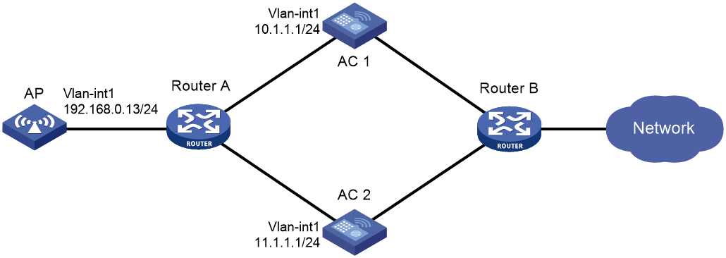
As shown in Figure 2, configure AC 1 to act as the master AC and AC 2 as the backup AC. When AC 1 fails and AC 2 takes over, the AP can communicate through AC 2. Configure the master CAPWAP tunnel preemption feature on the two ACs so that the AP reconnects to AC 1 when AC 1 recovers.
Procedure
1. Configure AC 1:
# Create VLAN-interface 1 and assign an IP address to it.
<AC1> system-view
[AC1] interface vlan-interface 1
[AC1-Vlan-interface1] ip address 10.1.1.1 24
[AC1-Vlan-interface1] quit
# Create an AP named ap1, and specify the AP model and serial ID. Set the AP connection priority to 7.
[AC1] wlan ap ap1 model WA6320
[AC1-wlan-ap-ap1] serial-id 219801A28N819CE0002T
[AC1-wlan-ap-ap1] priority 7
[AC1-wlan-ap-ap1] backup-ac ip 11.1.1.1
# Enable master CAPWAP tunnel preemption.
[AC1-wlan-ap-ap1] wlan tunnel-preempt enable
[AC1-wlan-ap-ap1] quit
2. Configure AC 2:
# Create VLAN-interface 1 and assign an IP address to it.
<AC2> system-view
[AC2] interface Vlan-interface 1
[AC2-Vlan-interface1] ip address 11.1.1.1 24
[AC2-Vlan-interface1] quit
# Create an AP named ap1, and specify the AP model and serial ID. Set the AP connection priority to 5.
[AC2] wlan ap ap1 model WA6320
[AC2-wlan-ap-ap1] serial-id 219801A28N819CE0002T
[AC2-wlan-ap-ap1] priority 5
# Specify a backup AC.
[AC2-wlan-ap-ap1] backup-ac ip 10.1.1.1
# Enable master CAPWAP tunnel preemption.
[AC2-wlan-ap-ap1] wlan tunnel-preempt enable
[AC2-wlan-ap-ap1] quit
Verifying the configuration
# Get the AP online on AC 1. (Details not shown.)
# Shut down VLAN-interface 1 on AC 1 and wait no longer than 3 minutes, during which service interruption occurs. (Details not shown.)
# Verify that the AP comes online on AC 2 and the AP state is R/M on AC 2. (Details not shown.)
# Bring up VLAN-interface 1 on AC 1. (Details not shown.)
# Verify that the AP comes online on AC 1 again and the AP state is R/M on AC 1 and R/B in AC 2. (Details not shown.)
Configuring AP backup
About AP backup
AP backup forms multiple ACs into a cloud cluster to ensure centralized AP management and avoid wireless service interruption in case of AC failures.
AC roles
An AC has the following roles:
|
Role |
Description |
|
Master AC |
Master in a cloud cluster. The master AC manages the entire cloud cluster. |
|
Subordinate AC |
Subordinate in a cloud cluster. A subordinate AC processes services, forwards packets, and acts as a backup for the master AC. When the master AC fails, the system automatically elects a new master AC from the subordinate ACs in the cloud cluster. |
|
Active AC |
An AC that can establish CAPWAP tunnels with APs. The master AC is always an active AC. |
|
Non-active AC |
An AC that cannot establish CAPWAP tunnels with APs. Non-active ACs can only be subordinate ACs. When an active AC fails, a non-active AC will be elected as an active AC. |
|
Directly connected AC |
An AC that receives the first packet from an AP when the AP launches a CAPWAP tunnel establishment process. |
|
Non-directly connected AC |
An AC that does not receive the first packet from an AP when the AP launches a CAPWAP tunnel establishment process. |
AP backup and recovery
AP backup enables the active AC (master AC) in a cloud cluster to synchronize information about connected APs to all the non-active ACs. When the active AC fails, one of the non-active ACs becomes active to provide services, ensuring service continuity.
Prerequisites for AP backup
Before configuring AP backup, set up a cloud cluster for the target ACs. For information about cloud cluster, see Virtualization Configuration Guide.
Enabling AP backup
About this task
This feature enables the active AC to synchronize information about connected APs to all the non-active ACs. When the active AC fails, one of the non-active AC becomes active to provide services.
Restrictions and guidelines
Disabling this feature removes backup AP information from all ACs.
Procedure
1. Enter system view.
system-view
2. Enable AP backup.
wlan ap-backup hot-backup enable
By default, AP backup is disabled.
Configuring client backup
About client backup
Client backup enables cloud cluster member ACs to backup client information with each other to keep clients online in case of AC failures. Client backup is triggered every time client information changes.
Client backup must work with AP backup. After both features are enabled, active ACs back up connected AP and client information to other member ACs. When an active AC fails, the master AC will select another AC in the IRF fabric to recover information of AP and clients connected to the failed AC. For information about AP backup and AC selection, see "Configuring AP backup."
Restrictions and guidelines: Client backup configuration
Active ACs back up client information only for clients that come online after client backup is enabled. Disabling client backup deletes client backup information from all member ACs.
Prerequisites for client backup
The client backup feature must be used in conjunction with the AP backup feature. Client backup takes effect only when both features are enabled.
After you enable AP backup and client backup, the active AC can back up all connected APs and client information to other ACs within the cloud cluster. If the active AC fails, the master AC selects another AC to restore the AP and client information from the failed AC. For more information about AP backup and the AC selection rules, see "Configuring AP backup."
Enabling client backup
1. Enter system view.
system-view
2. Enable client backup.
wlan client-backup hot-backup enable
By default, client backup is disabled.
Setting the client backup delay
Restrictions and guidelines
This feature takes effect only when client backup is enabled.
This feature takes effect only on clients that come online after the client backup delay is set.
If an active/standby switchover occurs during the delay time, online clients whose information has not been backed up will be logged off and need to come online again. An active/standby switchover can be triggered by a restart of the active AC process.
Procedure
1. Enter system view.
system-view
2. Set the client backup delay.
wlan client-backup hot-backup delay delay-time
By default, the client backup delay is 60 seconds.
Display and maintenance commands for client backup
Execute display commands in any view.
|
Task |
Command |
|
Display backup information about 802.1X clients associated with the specified cloud cluster member device. |
display dot1x connection-backup [ ap ap-name [ radio radio-id ] ] slot slot-number |
|
Display backup information about MAC authentication clients associated with the specified cloud cluster member device. |
display mac-authentication connection-backup [ ap ap-name [ radio radio-id ] ] slot slot-number |
|
Display client backup information for the specified cloud cluster member device. |
display wlan client-backup [ ap ap-name [ radio radio-id ] | mac-address mac-address ] [ verbose ] [ slot slot-number ] |
Configuring WLAN VSRP
About WLAN VSRP
WLAN Virtual Service Redundancy Protocol (VSRP) establishes a data backup tunnel between the master AC and backup AC for real-time synchronization of WLAN service data. If the master AC or the link to the master AC fails, the backup AC takes over services to ensure service continuity.
For more information about VSRP, see High Availability Configuration Guide.
Restrictions and guidelines: WLAN VSRP
· Make sure the master AC and backup AC are associated with the same VSRP instance.
· Data backup is not supported if the master and backup ACs use different versions.
· WLAN VSRP is available only in AC hair-pin deployment. Make sure the ACs do not act as a gateway or DHCP server.
· If you enable accounting-on, WLAN VSRP does not take effect.
· With WLAN VSRP configured, do not enable STP on the switch interfaces that connect the switch to the ACs in the VRRP group. If STP is configured globally, specify the switch interfaces as edge interfaces.
· To avoid data backup failure, make sure the master and backup ACs meet the following requirements:
¡ The two ACs have the same software version, and use consistent authentication, VSRP, and service template settings.
¡ Service templates are bound to APs or AP groups in the same order on both ACs.
· To use remote 802.1X or MAC authentication, configure the NAS-IP as the virtual IP address of VRRP on the master and backup ACs.
· Make sure VSRP, VRRP, and AP association use the same VLAN.
· Do not bind a VRRP service VLAN to multiple physical interfaces.
· As a best practice to ensure system stability, set the VRRP advertisement interval for notification packets to a value larger than 300 centiseconds.
· In VRRP preemptive mode, retain the default preemption delay (60 minutes) as a best practice. To change the preemption delay, set the delay to a value longer than 10 minutes as a best practice.
· To support hot backup-incapable APs, configure AP connection priorities on the ACs for APs to establish master tunnels with the master AC and backup tunnels with the backup AC.
· For APs to use static configuration to obtain AC addresses, you must specify the AC IP addresses for APs manually.
· If auto AP is configured, convert auto APs to manual APs before configuring VSRP.
· WLAN VSRP does not support using a virtual IP address as the access IP address for an AP.
· If you add a service template to the master and backup ACs, execute the save command to save the configuration, and then use the reboot command to reboot the ACs.
· This feature is not supported in IPv6 networks.
Associating the AC with a VSRP instance
1. Enter system view.
system-view
2. Enter global configuration view.
wlan global-configuration
3. Associate the AC with a VSRP instance.
vsrp-instance vsrp-instance-name
By default, the AC is not associated with a VSRP instance.
Specifying the TCP port number for establishing a wireless client backup data channel
About this task
To back up wireless client data in real time, the master and the backup must establish a backup TCP data channel. You can change the TCP port number as needed.
Restrictions and guidelines
Changing the port number disconnects the current TCP backup tunnel. The ACs will use the new port to establish a new tunnel.
Procedure
1. Enter system view.
system-view
2. Enter global configuration view.
wlan global-configuration
3. Specify a TCP port number for VSRP to establish a data channel for wireless client data backup.
client vsrp-port port-number
By default, the TCP port number is 60048.
Triggering a manual switchback for a VRRP group
About this task
In a VRRP group, if the master AC or the master link fails, the backup AC takes over services and becomes the new master AC. If the failed AC recovers, you can perform this task for the AC to become the master AC again and set a delay time for the configuration to take effect.
Restrictions and guidelines
Make sure the master AC has a higher priority than the backup AC.
For the switchback to take effect, you must perform the task on both the master and backup ACs and set the same delay time.
Procedure
1. Enter system view.
system-view
2. Enter interface view.
interface interface-type interface-number
3. Trigger a switchback in the VRRP group in non-preemptive mode and set the delay time.
vrrp vrid virtual-router-id manual-preempt [ delay-time time-value ]
By default, the system does not perform switchback after a master/backup switchover.
For more information about this command, see VRRP commands in High Availability Command Reference.
Verifying and maintaining WLAN VSRP
To display WLAN VSRP instance information, execute the following command in any view:
display wlan client vsrp instance [ instance-name ]
WLAN VSRP configuration examples
Example: Configuring WLAN VSRP
Network configuration
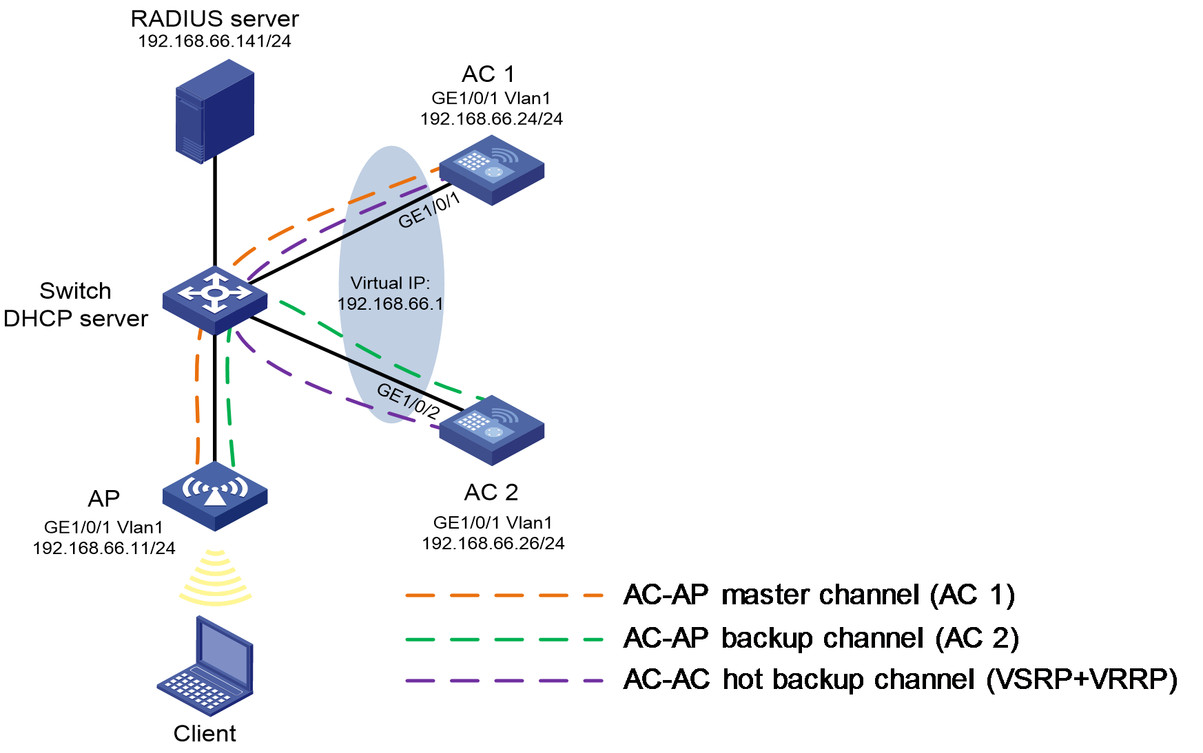
As shown in Figure 3, AC 1, AC 2, and the AP connect to each other through the switch to form a dual-link network. Configure WLAN VSRP to establish a VRRP+VSRP hot backup tunnel between the ACs and configure 802.1X EAP-PEAP authentication. The switch acts as the DHCP server to assign IP addresses to clients. AC 1, AC 2, and the AP use IP addresses 192.168.66.24, 192.168.66.26, and 192.168.66.11, respectively.
Procedure
1. Configure interface IP addresses and global route settings. (Details not shown.)
2. Configure the RADIUS server:
|
|
NOTE: In this example, the RADIUS server runs IMC V7. |
# Add an access device.
a. Log in to IMC and click the User tab.
b. From the navigation pane, select User Access Policy > Access Device Management > Access Device.
c. Click Add.
- Specify the shared key for authentication and accounting to 12345678, and retain the default settings in the other fields.
- Select or manually add device at 192.168.66.1 (VRRP virtual IP address) as an access device.
# Add an access policy.
a. Click the User tab.
b. From the navigation pane, select User Access Policy > Access Policy.
c. Click Add.
- Specify the policy name as dot1x.
- Select EAP for the Certificate Authentication field.
- Select EAP-PEAP as the certificate type and MS-CHAPV2 as the sub-type. Make sure the subtype is consistent with the client authentication method.
# Add an access service.
a. Click the User tab.
b. From the navigation pane, select User Access Policy > Access Service.
c. Click Add.
- Enter dot1x as the service name.
- Select dot1x as the default access policy.
# Add an access user.
a. Click the User tab.
b. From the navigation pane, select Access User > All Access Users.
c. Click Add.
- Set the username to user.
- Set the account name and password to user and dot1x, respectively.
- Select service dot1x for the user.
3. Configure AC 1:
¡ Configure VRRP:
# Create VRRP group 1, set its virtual IP address to 192.168.66.1, and set the AC priority to 250 on VLAN-interface 1. The priority is higher than the priority configured on AC 2.
<AC1> system-view
[AC1] interface vlan-interface 1
[AC1-Vlan-interface1] vrrp vrid 1 virtual-ip 192.168.66.1
[AC1-Vlan-interface1] vrrp vrid 1 priority 250
# Configure AC 1 to operate in preemptive mode, and set the preemption delay to 120000 centiseconds (20 minutes).
[AC1-Vlan-interface1] vrrp vrid 1 preempt-mode delay 120000
[AC1-Vlan-interface1] quit
¡ Configure VSRP-track collaboration:
# Configure track entry 1, and associate it with interface GigabitEthernet 1/0/1. If the state of the track entry is Negative, it indicates that the VRRP, VSRP, or CAPWAP link is faulty.
[AC1] track 1 interface gigabitethernet1/0/1
¡ Configure VSRP:
# Create VSRP peer pname, specify the peer IP address as 192.168.66.26, and specify the local IP address as 192.168.66.24. This configuration enables AC 1 to use VLAN-interface 1 to establish the backup data tunnel for VSRP.
[AC1] vsrp peer pname
[AC1-vsrp-peer-pname] peer 192.168.66.26 local 192.168.66.24
# Associate VSRP peer pname with track entry 1.
[AC1-vsrp-peer-pname] track 1
[AC1-vsrp-peer-pname] quit
# Create VSRP instance inst, associate the instance with VSRP group pname, and set the backup ID of the instance to 1.
[AC1] vsrp instance inst
[AC1-vsrp-instance-inst] backup id 1 peer pname
# Bind the VSRP instance to VRRP group 1 on interface VLAN-interface 1.
[AC1-vsrp-instance-inst] bind vrrp vrid 1 interface vlan-interface1
[AC1-vsrp-instance-inst] quit
# Associate VSRP instance inst to AC 1.
[AC1] wlan global-configuration
[AC1-wlan-global-configuration] vsrp-instance inst
[AC1-wlan-global-configuration] quit
¡ Configure AAA:
# Configure EAP relay.
[AC1] dot1x authentication-method eap
# Create RADIUS scheme imc. Specify the primary authentication server and primary account server, and set the shared key for authentication and accounting to 12345678 in plaintext.
[AC1] radius scheme imc
[AC1-radius-imc] primary authentication 192.168.66.141 key simple 12345678
[AC1-radius-imc] primary accounting 192.168.66.14 key simple 12345678
# Exclude domain names from the usernames sent to the RADIUS server, and specify the source IP address for outgoing RADIUS packets as 192.168.66.1.
[AC1-radius-imc] user-name-format without-domain
[AC1-radius-imc] nas-ip 192.168.66.1
[AC1-radius-imc] quit
# Create ISP domain dot1x, and apply RADIUS scheme imc to the ISP domain for authentication, authorization, and accounting.
[AC1] domain dot1x
[AC1-isp-dot1x] authentication lan-access radius-scheme imc
[AC1-isp-dot1x] authorization lan-access radius-scheme imc
[AC1-isp-dot1x] accounting lan-access radius-scheme imc
[AC1-isp-dot1x] quit
¡ Configure the service template:
# Create service template wlas_imc_dot1x, and configure the 802.1X authentication mode. Specify the ISP domain, SSID, AKM mode, cipher suite, and security IE as domain dot1x, wlas_imc_dot1x, 802.1X, CCMP, and RSN, respectively.
[AC1] wlan service-template wlas_imc_dot1x
[AC1-wlan-st-wlas_imc_dot1x] client-security authentication-mode dot1x
[AC1-wlan-st-wlas_imc_dot1x] dot1x domain dot1x
[AC1-wlan-st-wlas_imc_dot1x] ssid wlas_imc_dot1x
[AC1-wlan-st-wlas_imc_dot1x] akm mode dot1x
[AC1-wlan-st-wlas_imc_dot1x] cipher-suite ccmp
[AC1-wlan-st-wlas_imc_dot1x] security-ie rsn
# Enable the service template.
[AC1-wlan-st-wlas_imc_dot1x] service-template enable
[AC1-wlan-st-wlas_imc_dot1x] quit
¡ Configure the AP:
# Create AP ap1.
[AC1] wlan ap ap1 model WA6320
[AC1-wlan-ap-ap1] serial-id 219801A28N819CE0002T
# Specify the working channel of radio 1 as channel 149, and enable the radio.
[AC1-wlan-ap-ap1] radio 1
[AC1-wlan-ap-ap1-radio-1] channel 149
[AC1-wlan-ap-ap1-radio-1] radio enable
# Bind service template wlas_imc_dot1x to radio 1.
[AC1-wlan-ap-ap1-radio-1] service-template wlas_imc_dot1x
[AC1-wlan-ap-ap1-radio-1] quit
[AC1-wlan-ap-ap1] quit
¡ Save the configuration and restart the AC.
[AC1] save
The current configuration will be written to the device. Are you sure? [Y/N]:y
Please input the file name(*.cfg)[flash:/startup.cfg]
(To leave the existing filename unchanged, press the enter key):
flash:/startup.cfg exists, overwrite? [Y/N]:y
Validating file. Please wait...
Configuration is saved to device successfully.
[AC2] quit
<AC2> reboot
Start to check configuration with next startup configuration file, please wait..
.......DONE!
Current configuration may be lost after the reboot, save current configuration?
[Y/N]:y
This command will reboot the device. Continue? [Y/N]:y
4. Configure AC 2:
¡ Configure VRRP:
# Create VRRP group 1, set its virtual IP address to 192.168.66.1, and set the AC priority to 200 on VLAN-interface 1. The priority is lower than the priority configured on AC 1.
<AC2> system-view
[AC2] interface vlan-interface 1
[AC2-Vlan-interface1] vrrp vrid 1 virtual-ip 192.168.66.1
[AC2-Vlan-interface1] vrrp vrid 1 priority 200
# Configure AC 2 to operate in preemptive mode, and set the preemption delay to 120000 centiseconds (20 minutes).
[AC2-Vlan-interface1] vrrp vrid 1 preempt-mode delay 120000
[AC2-Vlan-interface1] quit
¡ Configure VSRP-track collaboration:
# Configure track entry 1, and associate it with interface GigabitEthernet 1/0/2. If the state of the track entry is Negative, it indicates that the VRRP, VSRP, or CAPWAP link is faulty.
[AC2] track 1 interface gigabitethernet1/0/2
¡ Configure VSRP:
# Create VSRP peer pname, specify the peer IP address as 192.168.66.24, and specify the local IP address as 192.168.66.26. This configuration enables AC 2 to use VLAN-interface 1 to establish the backup data tunnel for VSRP.
[AC2] vsrp peer pname
[AC2-vsrp-peer-pname] peer 192.168.66.24 local 192.168.66.26
# Associate VSRP peer pname with track 1.
[AC2-vsrp-peer-pname] track 1
[AC2-vsrp-peer-pname] quit
# Create VSRP instance inst, associate the instance with VSRP group pname, and set the backup ID of the instance to 1.
[AC2] vsrp instance inst
[AC2-vsrp-instance-inst] backup id 1 peer pname
# Bind the VSRP instance to VRRP group 1 on interface VLAN-interface 1.
[AC2-vsrp-instance-inst] bind vrrp vrid 1 interface vlan-interface1
[AC2-vsrp-instance-inst] quit
# Associate VSRP instance inst to AC 1.
[AC2] wlan global-configuration
[AC2-wlan-global-configuration] vsrp-instance inst
[AC2-wlan-global-configuration] quit
¡ Configure AAA:
# Configure EAP relay.
[AC2] dot1x authentication-method eap
# Create RADIUS scheme imc. Specify the primary authentication server and primary account server, and set the shared key for authentication and accounting to 12345678 in plaintext.
[AC2] radius scheme imc
[AC2-radius-imc] primary authentication 192.168.66.141 key simple 12345678
[AC2-radius-imc] primary accounting 192.168.66.141 key simple 12345678
# Exclude domain names from the usernames sent to the RADIUS server, and specify the source IP address for outgoing RADIUS packets as 192.168.66.1.
[AC2-radius-imc] user-name-format without-domain
[AC2-radius-imc] nas-ip 192.168.66.1
[AC2-radius-imc] quit
# Create ISP domain dot1x, and apply RADIUS scheme imc to the ISP domain for authentication, authorization, and accounting.
[AC2] domain dot1x
[AC2-isp-dot1x] authentication lan-access radius-scheme imc
[AC2-isp-dot1x] authorization lan-access radius-scheme imc
[AC2-isp-dot1x] accounting lan-access radius-scheme imc
[AC2-isp-dot1x] quit
¡ Configure the service template:
# Create service template wlas_imc_dot1x, and configure the 802.1X authentication mode. Specify the ISP domain, SSID, AKM mode, cipher suite, and security IE as domain dot1x, wlas_imc_dot1x, 802.1X, CCMP, and RSN, respectively.
[AC2] wlan service-template wlas_imc_dot1x
[AC2-wlan-st-wlas_imc_dot1x] client-security authentication-mode dot1x
[AC2-wlan-st-wlas_imc_dot1x] dot1x domain dot1x
[AC2-wlan-st-wlas_imc_dot1x] ssid wlas_imc_dot1x
[AC2-wlan-st-wlas_imc_dot1x] akm mode dot1x
[AC2-wlan-st-wlas_imc_dot1x] cipher-suite ccmp
[AC2-wlan-st-wlas_imc_dot1x] security-ie rsn
# Enable the service template.
[AC2-wlan-st-wlas_imc_dot1x] service-template enable
[AC2-wlan-st-wlas_imc_dot1x] quit
¡ Configure the AP:
# Create AP ap1.
[AC2] wlan ap ap1 model WA6320
[AC2-wlan-ap-ap1] serial-id 219801A28N819CE0002T
# Specify the working channel of radio 1 as channel 149, and enable the radio.
[AC2-wlan-ap-ap1] radio 1
[AC2-wlan-ap-ap1-radio-1] channel 149
[AC2-wlan-ap-ap1-radio-1] radio enable
# Bind service template wlas_imc_dot1x to radio 1.
[AC2-wlan-ap-ap1-radio-1] service-template wlas_imc_dot1x
[AC2-wlan-ap-ap1-radio-1] quit
[AC2-wlan-ap-ap1] quit
¡ Save the configuration and restart the AC.
[AC2] save
The current configuration will be written to the device. Are you sure? [Y/N]:y
Please input the file name(*.cfg)[flash:/startup.cfg]
(To leave the existing filename unchanged, press the enter key):
flash:/startup.cfg exists, overwrite? [Y/N]:y
Validating file. Please wait...
Configuration is saved to device successfully.
[AC2] quit
<AC2> reboot
Start to check configuration with next startup configuration file, please wait..
.......DONE!
Current configuration may be lost after the reboot, save current configuration?
[Y/N]:y
This command will reboot the device. Continue? [Y/N]:y
Verifying the configuration
# Verify that AC 1 is the master device, AC 2 is the backup device, and both channels are in up state.
[AC1] display wlan client vsrp instance inst
VSRP instance name : inst
Instance peer address : 192.168.66.26
Instance status : Master
Channel status : Up
Created at : 2021-11-30 15:51:26
[AC2] display wlan client vsrp instance inst
VSRP instance name : inst
Instance peer address : 192.168.66.24
Instance status : Backup
Channel status : Up
Created at : 2021-11-30 10:55:30
# Connect the client to wireless service wlas_imc_dot1x, and enter username user and password dot1x. For an Android terminal, if you select MSCHAPV2, you can skip CA certificate verification. To verify CA certificate, you must install the certificate on the terminal.
# Display 802.1X user connections on AC 1 and AC 2.
[AC1] display dot1x connection
Total connections: 1
User MAC address : aa22-40a8-aa85
AP name : ap1
Radio ID : 1
SSID : wlas_imc_dot1x
BSSID : 0868-8dfd-1650
Username : user
Authentication domain : imc
IPv4 address : 192.168.66.172
Authentication method : EAP
Initial VLAN : 1
Authorization VLAN : 1
Authorization ACL number : N/A
Authorization user profile : N/A
Authorization CAR : N/A
Termination action : Default
Session timeout last from : 2021/11/30 21:08:27
Session timeout period : 86400 s
Online from : 2021/11/30 21:08:27
Online duration : 0h 0m 3s
[AC2] display dot1x connection-backup
Total backup connections: 1
User MAC address : aa22-40a8-aa85
AP name : ap1
Radio ID : 1
SSID : wlas_imc_dot1x
BSSID : 0868-8dfd-1650
Username : dot1x
Authentication domain : imc
IPv4 address : 192.168.66.172
Authentication method : EAP
Initial VLAN : 1
Authorization VLAN : 1
Authorization ACL number : N/A
Authorization user profile : N/A
Authorization CAR : N/A
Termination action : Default
Session timeout period : 86400 s
Online from : 2021/11/30 21:08:27
Online duration : 0h 1m 35s
# View user information on AC 1 and AC 2.
[AC1] display wlan client
Total number of clients: 1
MAC address User name AP name R IP address VLAN
aa22-40a8-aa85 user ap1 1 192.168.66.172 1
[AC2] display wlan client-backup
Total number of clients: 1
MAC address User name AP name R IP address VLAN
aa22-40a8-aa85 user ap1 1 192.168.66.172 1
Example: Configuring manually-triggered preemption in an IPv4 VRRP group
Network configuration
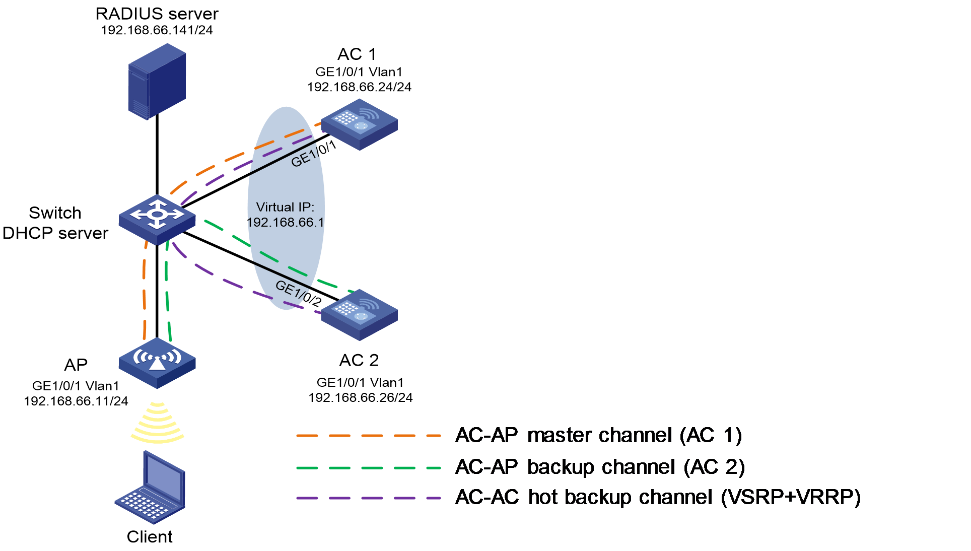
As shown in Figure 4, the AP connects to AC 1 and AC 2 through the switch to form a dual-link network. Configure VRRP+VSRP for AC 1 and AC 2, and configure the switch to act as the DHCP server to assign IP addresses to the client. In this example, the IP address of AC 1 is 192.168.66.24, the IP address of AC 2 is 192.168.66.26, and the IP address of the AP is 192.168.66.11.
Manually trigger a preemption after master/backup AC switchover for AC 1 to work as the master AC again.
Procedure
1. Configure AC 1:
# Create VRRP group 1 on interface Vlan-Interface 1, set the virtual IP address to 192.168.66.1, and set the AC priority to 250. The priority is higher than the priority configured on AC 2.
<AC1> system-view
[AC1] interface vlan-interface 1
[AC1-Vlan-interface1] vrrp vrid 1 virtual-ip 192.168.66.1
[AC1-Vlan-interface1] vrrp vrid 1 priority 250
# Manually trigger a preemption in the IPv4 VRRP group and set the delay time to 120 minutes.
[AC1-Vlan-interface1] vrrp vrid 1 manual-preempt delay-time 120
[AC1-Vlan-interface1]quit
2. Configure AC 2:
# Create VRRP group 1 on interface Vlan-Interface 1, set the virtual IP address to 192.168.66.1, and set the AC priority to 200. The priority is lower than the priority configured on AC 1.
<AC1> system-view
[AC1] interface vlan-interface 1
[AC1-Vlan-interface1] vrrp vrid 1 virtual-ip 192.168.66.1
[AC1-Vlan-interface1] vrrp vrid 1 priority 250
# Manually trigger a preemption in the IPv4 VRRP group and set the delay time to 120 minutes.
[AC1-Vlan-interface1] vrrp vrid 1 manual-preempt delay-time 120
[AC1-Vlan-interface1]quit
Verifying the configuration
# Verify that AC 1 is the master device, AC 2 is the backup device, and both channels are in up state.
[AC1] display wlan client vsrp instance inst
VSRP instance name : inst
Instance peer address : 192.168.66.26
Instance status : Master
Channel status : Up
Created at : 2021-11-30 15:51:26
[AC2] display wlan client vsrp instance inst
VSRP instance name : inst
Instance peer address : 192.168.66.24
Instance status : Backup
Channel status : Up
Created at : 2021-11-30 10:55:30