- Table of Contents
-
- H3C Campus Fixed-Port Switches CLI-Based Quick Start Configuration Guide -6W102
- 01-H3C Devices CLI Reference
- 02-Login Management Quick Start Configuration Guide
- 03-Configuration File Management Quick Start Configruation Guide
- 04-Software Upgrade Quick Start Configuration Guide
- 05-Device Management Quick Start Configuration Guide
- 06-NTP Quick Start Configuration Guide
- 07-RBAC Quick Start Configuration Guide
- 08-IRF Quick Start Configuration Guide
- 09-Ethernet Interface Quick Start Configuration Guide
- 10-VLAN Quick Start Configuration Guide
- 11-Port Isolation Quick Start Configuration Guide
- 12-Loop Detection Quick Start Configuration Guide
- 13-QinQ Quick Start Configuration Guide
- 14-MAC Address Table Quick Start Configuration Guide
- 15-Ethernet Link Aggregation Quick Start Configuration Guide
- 16-Spanning Tree Quick Start Configuration Guide
- 17-DHCP Quick Start Configuration Guide
- 18-OSPF Quick Start Configuration Guide
- 19-Static Routing Quick Start Configuration Guide
- 20-Basic RIP Quick Start Configuration Guide
- 21-PBR Quick Start Configuration Guide
- 22-IGMP Snooping Quick Start Configuration Guide
- 23-Packet Filtering Quick Start Configuration Guide
- 24-QoS Quick Start Configuration Guide
- 25-IP Source Guard Quick Start Configuration Guide
- 26-SSH Quick Start Configuration Guide
- 27-Port Security Quick Start Configuration Guide
- 28-VRRP Quick Start Configuration Guide
- 29-PoE Quick Start Configuration Guide
- 30-Mirroring Quick Start Configuration Guide
- 31-Information Center Quick Start Configuration Guide
- 32-SNMP Quick Start Configuration Guide
- 33-Static Route-Based Public and Private Network Intercommunication Configuration Guide
- 34-LAN Networks Quick Start Configuration Guide
- 35-802.1X Quick Start Configuration Guide
- 36-AAA Quick Start Configuration Guide
- Related Documents
-
| Title | Size | Download |
|---|---|---|
| 09-Ethernet Interface Quick Start Configuration Guide | 164.56 KB |
Ethernet Interface Quick Start Configuration Guide
Copyright © 2025 New H3C Technologies Co., Ltd. All rights reserved.
No part of this manual may be reproduced or transmitted in any form or by any means without prior written consent of New H3C Technologies Co., Ltd.
Except for the trademarks of New H3C Technologies Co., Ltd., any trademarks that may be mentioned in this document are the property of their respective owners.
The information in this document is subject to change without notice.
Contents
Activating the copper port or fiber port of a combo interface
Configuring the speed and duplex mode for Ethernet interfaces
Configuring the link mode for Ethernet interfaces
Activating the copper port or fiber port of a combo interface
Introduction
The following information uses an example to describe the basic procedure for activating the copper port or fiber port of a combo interface.
Network configuration
Activate the copper port or fiber port of a combo interface at the CLI.
Restrictions and guidelines
A combo interface is a logical interface that physically comprises one fiber combo port and one copper combo port on the device panel. The two ports share one forwarding interface and one interface view. As a result, they cannot work simultaneously. When you activate one port, the other port is automatically disabled.
Procedure
# Activate the copper combo port of GigabitEthernet 1/0/1, and connect a twisted pair cable to the interface.
<Sysname> system-view
[Sysname] interface gigabitethernet 1/0/1
[Sysname-GigabitEthernet1/0/1] combo enable copper
[Sysname-GigabitEthernet1/0/1] quit
# Activate the fiber combo port of GigabitEthernet 1/0/1, and connect a fiber to the interface.
<Sysname> system-view
[Sysname] interface gigabitethernet 1/0/1
[Sysname-GigabitEthernet1/0/1] combo enable fiber
[Sysname-GigabitEthernet1/0/1] quit
Verifying the configuration
# When a combo interface is connected to a cable or transceiver module, use the display interface command to view information about the interface. If Media type is twisted pair is displayed in the command output, the copper port is activated. If not, the fiber port is activated.
[Sysname] display interface GigabitEthernet 1/0/1
GigabitEthernet1/0/1
Current state: DOWN
Line protocol state: DOWN
IP packet frame type: Ethernet II, hardware address: 00ff-00ff-0139
Description: GigabitEthernet1/0/1 Interface
Bandwidth: 1000000 kbps
Loopback is not set
Media type is twisted pair
Port hardware type is 1000_BASE_T
Unknown-speed mode, unknown-duplex mode
Link speed type is autonegotiation, link duplex type is autonegotiation
…
Configuration files
#
interface GigabitEthernet1/0/1
port link-mode bridge
combo enable copper
#
Related documentation
· Ethernet interface configuration in the Layer 2—Ethernet switching configuration guide for the device.
· Ethernet interface commands in the Layer 2—Ethernet switching command reference for the device.
Configuring the speed and duplex mode for Ethernet interfaces
Introduction
The following information uses an example to describe the basic procedure for configuring the speed and duplex mode for Ethernet interfaces.
Network configuration
As shown in Figure 1:
· The server group (Server 1, Server 2 and Server 3) are connected to GigabitEthernet 1/0/1, GigabitEthernet 1/0/2 and GigabitEthernet 1/0/3 on the switch, respectively.
· The switch is connected to the Internet through GigabitEthernet 1/0/4.
Because of the limitations of the server NICs, the following issues exist:
· GigabitEthernet 1/0/1, GigabitEthernet 1/0/2, and GigabitEthernet 1/0/3 can only negotiate to operate in half-duplex mode. In half-duplex mode, packet loss will occur when the service data traffic is high.
· GigabitEthernet 1/0/1, GigabitEthernet 1/0/2, and GigabitEthernet 1/0/3 negotiate the speed to a maximum of 1000 Mbps. When the server group simultaneously sends data to the external network at a speed of 1000 Mbps, congestion occurs on GigabitEthernet 1/0/4.
Use this example to resolve the packet loss and congestion issues.

Analysis
· To avoid packet loss, set the duplex mode to full duplex.
· To avoid data congestion, configure the interfaces to operate at 100 Mbps.
Procedure
# Add GigabitEthernet 1/0/1 through GigabitEthernet 1/0/3 to interface range myEthPort, and enter the interface range view.
<H3C> system-view
[H3C] sysname Switch
[Switch] interface range name myEthPort interface gigabitethernet 1/0/1 to gigabitethernet 1/0/3
[Sysname-if-range-myEthPort]
# Configure GigabitEthernet 1/0/1 through GigabitEthernet 1/0/3 to operate in full-duplex mode and at 100 Mbps.
[Sysname-if-range-myEthPort] duplex full
[Sysname-if-range-myEthPort] speed 100
[Sysname-if-range-myEthPort] quit
|
|
Note: After you execute the commands in interface range view, the device issues the configuration to GigabitEthernet 1/0/1, GigabitEthernet 1/0/2, and GigabitEthernet 1/0/3, and displays the configuration information for each interface. |
Verifying the configuration
# Execute the display interface command in any view to check the current operating speed and duplex mode of GigabitEthernet 1/0/1.
[Switch] display interface gigabitethernet 1/0/1
...
Media type is twisted pair, port hardware type is 1000_BASE_T
Port priority: 0
100Mbps-speed mode, Full-duplex mode
Link speed type is force link, link duplex type is force link
Flow-control is not enabled
Maximum frame length: 12288 ...
The output shows that the interface is operating in full duplex mode at 100 Mbps.
View the current operating speed and duplex mode of GigabitEthernet 1/0/2 and GigabitEthernet 1/0/3 in the same way.
Configuration files
#
sysname Switch
#
interface range name myEthPort interface gigabitethernet 1/0/1 to gigabitethernet 1/0/3
#
Related documentation
· Ethernet interface configuration in the Layer 2—Ethernet switching configuration guide for the device.
· Ethernet interface commands in the Layer 2—Ethernet switching command reference for the device.
Configuring the link mode for Ethernet interfaces
Introduction
The following information uses an example to describe the basic procedure for configuring the link mode for Ethernet interfaces.
Network configuration
As shown in Figure 2:
· PC 1, PC 2, PC 3, and PC 4 belong to different network segments.
· Switch B, Switch C, Switch D, and Switch E are the access layer switches for these four network segments, respectively.
Configure the four Ethernet physical interfaces on Switch A as the gateway interfaces for these four network segments.
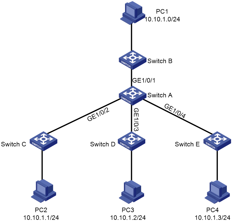
Analysis
· Set the link mode to route mode for the Ethernet interfaces.
· Configure the IP address of the Layer 3 interface as the gateway.
Procedure
1. Set the link mode of the Ethernet interfaces to route.
# Set the link mode of GigabitEthernet 1/0/1 through GigabitEthernet 1/0/4 to route.
<H3C> system-view
[H3C] sysname SwitchA
[SwitchA] interface gigabitethernet 1/0/1
[SwitchA-GigabitEthernet1/0/1] port link-mode route
[SwitchA-GigabitEthernet1/0/1] quit
[SwitchA] interface gigabitethernet 1/0/2
[SwitchA-GigabitEthernet1/0/2] port link-mode route
[SwitchA-GigabitEthernet1/0/2] quit
[SwitchA] interface gigabitethernet 1/0/3
[SwitchA-GigabitEthernet1/0/3] port link-mode route
[SwitchA-GigabitEthernet1/0/3] quit
[SwitchA] interface gigabitethernet 1/0/4
[SwitchA-GigabitEthernet1/0/4] port link-mode route
[SwitchA-GigabitEthernet1/0/4] quit
2. Configure the IP address of the Layer 3 interface as the gateway.
# Configure the IP address of GigabitEthernet 1/0/1 as the gateway.
[SwitchA] interface gigabitethernet 1/0/1
[SwitchA-GigabitEthernet1/0/1] ip address 10.10.1.1 24
[SwitchA-GigabitEthernet1/0/1] quit
|
|
NOTE: The configuration on GigabitEthernet 1/0/2, GigabitEthernet 1/0/3, and GigabitEthernet 1/0/4 is the same as that on GigabitEthernet 1/0/1. For more information, see the configuration guide. |
Verifying the configuration
# Execute the display interface command in any view to check the current duplex mode of an interface.
[SwitchA] display interface gigabitethernet 1/0/1
...
Unicast max-ratio: 100%
Internet protocol processing: Disabled
IP packet frame type: Ethernet II, hardware address: 3c8c-4002-8001
IPv6 packet frame type: Ethernet II, hardware address: 3c8c-4002-8001
Media type is not sure, port hardware type is no connector
Ethernet port mode: LAN
Port priority: 0
...
Configuration files
#
sysname SwitchA
#
interface GigabitEthernet1/0/1
port link-mode route
ip address 10.10.1.1 255.255.255.0
#
interface GigabitEthernet1/0/2
port link-mode route
ip address 10.10.2.1 255.255.255.0
#
interface GigabitEthernet1/0/3
port link-mode route
ip address 10.10.3.1 255.255.255.0
#
interface GigabitEthernet1/0/4
port link-mode route
ip address 10.10.4.1 255.255.255.0
#
Related documentation
· Ethernet interface configuration in the Layer 2—Ethernet switching configuration guide for the device.
· Ethernet interface commands in the Layer 2—Ethernet switching command reference for the device.
Configuring storm control
Introduction
The following information uses an example to describe the basic procedure for configuring storm control on an Ethernet interface.
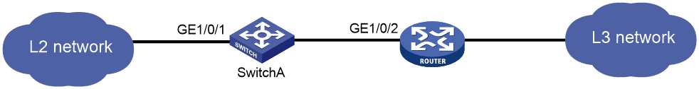
Network configuration
As shown in Figure 3, Switch A connects the Layer 2 network to the Layer 3 router. Configure storm control to restrict packet forwarding from the Layer 2 network.
Procedure
# Enter interface view.
<H3C> system-view
[H3C] sysname SwitchA
[SwitchA] interface gigabitethernet 1/0/1
# Enable broadcast storm control, and set the upper and lower thresholds to 2000 kbps and 1500 kbps, respectively.
[SwitchA-gigabitethernet 1/0/1] storm-constrain broadcast kbps 2000 1500
# Enable multicast storm control, and set the upper and lower thresholds to 80% and 15%, respectively.
[SwitchA-gigabitethernet 1/0/1] storm-constrain multicast ratio 80 15
# Enable unknown unicast storm control, and set the upper and lower thresholds to 200 pps and 150 pps, respectively.
[SwitchA-gigabitethernet 1/0/1] storm-constrain unicast pps 200 150
# Configure GigabitEthernet 1/0/1 to block a specific type of traffic when the type of traffic crosses the upper storm control threshold.
[SwitchA-GigabitEthernet1/0/1] storm-constrain control block
# Enable GigabitEthernet 1/0/1 to output log messages when it detects storm control threshold events.
[SwitchA-GigabitEthernet1/0/1] storm-constrain enable log
# Enable GigabitEthernet 1/0/1 to send traps when it detects storm control threshold events.
[SwitchA-GigabitEthernet1/0/1] storm-constrain enable trap
# Set the traffic statistics polling interval of the storm control module to 60 seconds.
[SwitchA-GigabitEthernet1/0/1] quit
[SwitchA] storm-constrain interval 60
Verifying the configuration
# Execute the display interface command on GigabitEthernet 1/0/1 to check the storm control configuration on the interface.
[SwitchA-GigabitEthernet1/0/1] display this
#
interface GigabitEthernet1/0/1
storm-constrain broadcast kbps 2000 1500
storm-constrain multicast ratio 80 15
storm-constrain unicast pps 200 150
storm-constrain control block
#
return
Configuration files
#
sysname SwitchA
#
interface GigabitEthernet1/0/1
storm-constrain broadcast kbps 2000 1500
storm-constrain multicast ratio 80 15
storm-constrain unicast pps 200 150
storm-constrain control block
storm-constrain enable log
storm-constrain enable trap
#
storm-constrain interval 60
#
Related documentation
· Ethernet interface configuration in the Layer 2—Ethernet switching configuration guide for the device.
· Ethernet interface commands in the Layer 2—Ethernet switching command reference for the device.
Configuring storm suppression
Introduction
The following information uses an example to describe the basic procedure for configuring storm suppression on an Ethernet interface.
Network configuration
As shown in Figure 4, Switch A connects the Layer 2 network to the Layer 3 router. Configure storm suppression to prevent broadcast storms generated by broadcast, multicast, or unknown unicast messages forwarded by the Layer 2 network.

Procedure
# Enter interface view.
<H3C> system-view
[H3C] sysname SwitchA
[SwitchA] interface gigabitethernet 1/0/1
# Set the broadcast suppression threshold to 10000 kbps on GigabitEthernet 1/0/1.
[SwitchA-GigabitEthernet1/0/1] broadcast-suppression kbps 10000
# Set the multicast suppression threshold to 10000 kbps on GigabitEthernet 1/0/1.
[SwitchA-GigabitEthernet1/0/1] multicast-suppression kbps 10000
# Set the unknown unicast suppression threshold to 10000 kbps on GigabitEthernet 1/0/1.
[SwitchA-GigabitEthernet1/0/1] unicast-suppression kbps 10000
Verifying the configuration
# Execute the display interface command on GigabitEthernet 1/0/1 to check the broadcast suppression configuration on the interface.
[SwitchA-GigabitEthernet1/0/1] display this
#
interface GigabitEthernet1/0/1
broadcast-suppression kbps 10000
multicast-suppression kbps 10000
unicast-suppression kbps 10000
#
return
Configuration files
#
sysname SwitchA
#
interface GigabitEthernet1/0/1
broadcast-suppression kbps 10000
multicast-suppression kbps 10000
unicast-suppression kbps 10000
#
Related documentation
· Ethernet interface configuration in the Layer 2—Ethernet switching configuration guide for the device.
· Ethernet interface commands in the Layer 2—Ethernet switching command reference for the device.
