- Table of Contents
-
- H3C S6116 Ultra-Low Latency Switch Series Configuration Guide-Release 671x-6W100
- 00-Preface
- 01-Interface forwarding configuration
- 02-CLI configuration
- 03-RBAC configuration
- 04-Login management configuration
- 05-FTP and TFTP configuration
- 06-File system management configuration
- 07-Configuration file management configuration
- 08-Software upgrade configuration
- 09-Device management configuration
- 10-Tcl configuration
- 11-Bulk interface configuration
- 12-IP addressing configuration
- 13-IPv6 basics configuration
- 14-Static routing configuration
- 15-IPv6 static routing configuration
- 16-AAA configuration
- 17-Public key management
- 18-SSH configuration
- 19-System maintenance and debugging configuration
- 20-NTP configuration
- 21-SNMP configuration
- 22-RMON configuration
- 23-Event MIB configuration
- 24-Information center configuration
- 25-PTP configuration
- 26-Network synchronization configuration
- Related Documents
-
| Title | Size | Download |
|---|---|---|
| 01-Interface forwarding configuration | 498.08 KB |
Contents
Configuring interface forwarding
About ultra-low latency switches
Configuring a Layer 1 Ethernet switch
Displaying the interconnection information of interfaces
Configuring the packet sending feature of a transceiver module
Configuring a Layer 1.5 Ethernet switch
Configure the mirroring feature for the multi-group SecurityMux mode
Configuring tapping aggregation
Configuring Ethernet interfaces
Restrictions and guidelines: Ethernet interface configuration
Configuring management Ethernet interfaces
Ethernet interface numbering conventions
Configuring basic settings for an Ethernet interface
Setting the statistics polling interval for an Ethernet interface
Displaying and maintaining interface forwarding
Interface forwarding configuration examples
Example: Configuring a Layer 1 Ethernet switch
Example: Configuring a Layer 1.5 Ethernet switch
Example: Configuring SecurityMux on a Layer 1.5 Ethernet switch
Configuring interface forwarding
About ultra-low latency switches
The ultra-low latency switches can achieve a low latency of 4 nanoseconds (ns), as opposed to 500 ns for traditional switches. The ultra-low latency switches significantly improve the forwarding efficiency.
The S6116 ultra-low latency switch series includes the S6116-48X Layer 1 Ethernet switches and the S6116-48X-M Layer 1.5 Ethernet switches.
The S6116 ultra-low latency switch series fast forwards and copies packets based on user configuration. The service interfaces of these switches do not support traditional Layer 2 or Layer 3 forwarding or related protocols.
Layer 1 Ethernet switch
A Layer 1 Ethernet switch operates at the physical layer, and can fast forward and copy packets based on user configuration, with latency as low as 4 ns. The H3C S6116 Ethernet switch series supports signal regeneration and amplification, and supports interface-based statistics collection for Ethernet packets. The switch series delivers both ultra-low latency and the maintainability of traditional Ethernet switches.
Layer 1 Ethernet switches support the following features:
· Patch panel—Enables traffic exchange between two interfaces.
· Fan-out—Enables 1:N traffic copying.
· Traffic statistics collection—You can use the display interface command to view traffic statistics.
· Interface status reporting.
Patch panel
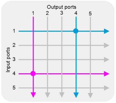
This feature allows bidirectional traffic exchange between any two interfaces of a Layer 1 Ethernet switch. Packets received on one interface will be directly forwarded to the other interface. As shown in Figure 1, after you configure this feature for port 1 and port 4, packets received on one port will be directly forwarded to the other port.
Fan-out
To send a packet to multiple receivers (for example, sending rapidly changing market data to multiple servers), a traditional switch or router broadcasts the packet to multiple ports in a specific VLAN or multicasts the packet to the specific ports. These two methods take at least 500 ns of latency.
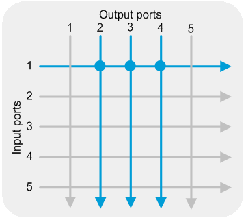
A Layer 1 Ethernet switch implements fast 1:N traffic copying through the fan-out feature. This feature fast copies traffic from one port to multiple ports, with latency as low as 4 ns. Layer 1 Ethernet switches support physical signal regeneration and clock data recovery, ensuring data integrity even after multiple copies. As shown in Figure 2, you can configure the fan-out feature to copy traffic from port 1 to ports 2, 3 and 4.
To configure fast interface forwarding, specify a source interface for the current interface. When a packet is received on the specified source interface, the packet will be directly forwarded out the current interface without table lookup. Fast interface forwarding provides both low latency and fast packet transmission.
Fast interface forwarding supports the following forwarding modes:
· 1:1—One source interface corresponds to one destination interface. Packets received on the specified source interface are forwarded out the specified destination interface.
· 1:N—One source interface corresponds to multiple destination interfaces. A copy of each packet received on the source interface is forwarded out each destination interface.
Layer 1.5 Ethernet switch
The H3C S6116-48X-M Layer 1.5 Ethernet switches support all the features of Layer 1 Ethernet switches, including fan-out and patch panel. They also support field programmable gate array (FPGA) cards and can load multiple FPGA applications. You can dynamically switch between different applications according to the network requirements to achieve different functions.
A Layer 1.5 Ethernet switch supports the following FPGA applications:
· FastMux—This application supports four Mux groups, which separately implement 15:1, 15:1, 7:1, and 7:1 upstream traffic multiplexing ratios with a minimum latency of 35 ns.
· SecurityMux—This application supports one Mux group with one upstream interface. This application supports a maximum upstream traffic multiplexing ratio of 47:1 and a maximum downstream traffic demultiplexing ratio of 1:47. This application supports ACL-based packet forwarding control on the outgoing interfaces of downstream traffic and a minimum latency of 59 ns.
· Enhanced SecurityMux—This application supports one Mux group with two upstream interfaces. This application supports a maximum upstream traffic multiplexing ratio of 46:2 and a maximum downstream demultiplexing ratio of 2:46. This application supports ACL-based packet forwarding control on the outgoing interfaces of upstream or downstream traffic.
· Multi-group SecurityMux—This application supports four Mux groups and four Demux groups. A Mux group can have one upstream interface. The groups separately implement 7:1, 7:1, 13:1, and 15:1 upstream traffic multiplexing ratios, and 1:7, 1:7, 1:13, 1:15 downstream traffic demultiplexing ratios. This application supports ACL-based packet forwarding control on the outgoing interfaces of downstream traffic. Two monitor ports are used to monitor the traffic of Mux groups.
· Tapping Aggregation—This application supports mirroring incoming traffic to other interfaces and load-sharing mirrored traffic among the monitor ports. You can configure a maximum of four monitor ports.
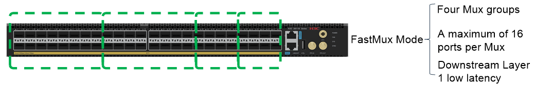
FastMux
FastMux is an applications designed for ultra-low latency. The downstream traffic is broadcast by the Layer 1 fan-out feature without FPGA processing. The upstream traffic is multiplexed by FPGA cards with a minimum latency of 35 ns. The switch supports configuring four Mux groups in FastMux mode. The software design is highly flexible, and allows you to dynamically move ports among groups according to the requirements.
Figure 3 FastMux group diagram (for illustration only)
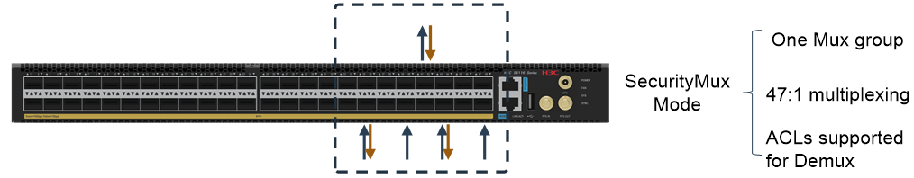
SecurityMux
SecurityMux is an application designed for secure data forwarding. The upstream traffic is multiplexed with a maximum ratio of 47:1 and scheduled by FPGA cards. The downstream traffic is demultiplexed by FPGA cards and supports ACL filtering based on the outgoing interfaces.
Figure 4 SecurityMux data forwarding diagram
|
|
Demux groups can control data forwarding by using ACLs. You can define ACL rules based on the quintuple including source IP address, source port, destination IP address, destination port, and TCP/UDP. A maximum of eight ACL rules can be applied to one interface.
Enhanced SecurityMux
Enhanced SecurityMux operates in the same way as SecurityMux, and is an application design for secure data forwarding. The upstream traffic is multiplexed with a maximum ratio of 46:2 and scheduled by FPGA cards. The downstream traffic is demultiplexed by FPGA cards. You can use ACLs to control packet forwarding on the outgoing interfaces of the upstream or downstream traffic.
Multi-group SecurityMux
Multi-group SecurityMux operates in the same way as SecurityMux, and is an application designed for secure data forwarding. This application supports four Mux groups. The upstream traffic is separately multiplexed with a ratio of 7:1, 7:1, 13:1, 15:1 and scheduled by FPGA cards. The downstream traffic is demultiplexed with a ratio of 1:7, 1:7, 1:13, 1:15 and scheduled by FPGA cards. This application supports ACL-based packet forwarding control on the outgoing interfaces of downstream traffic. Two monitor ports are used to monitor the traffic of Mux groups.
Tapping aggregation
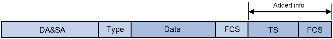
Tapping aggregation is an application designed for data mirroring. This feature mirrors and timestamps the packets of one or more ports, and aggregates them on up to four monitoring ports for traffic forwarding and backup. Traffic is load-shared among multiple monitoring ports.
After a packet is mirrored and aggregated, the packet has an additional 17-byte timestamp (TS) field and 4-byte frame check sequence (FCS) field at the end compared to the original packet.
![]()
Figure 6 Mirrored and aggregated packet
|
|
NOTE: If the length of the original packet exceeds 1518 bytes, the mirrored and aggregated packet will be truncated to the first 1518 bytes and then the TS and FCS fields will be added. |
As shown in Figure 7, the TS field contains 17 bytes, including a complete timestamp in CF field format and packet information.
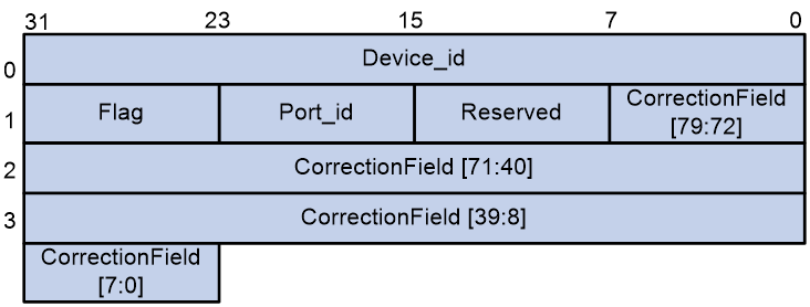
The fields are described as follows:
· Device_id: A 4-byte string indicating the device ID.
|
|
NOTE: · Only the primary IPv4 address of the management Ethernet interface on the device can be used as the device ID. Secondary IPv4 addresses and IPv6 addresses cannot be used as the device ID. · If the management Ethernet interface is only configured with secondary IPv4 addresses or IPv6 addresses, the device ID is 0. |
· Flag: 1 byte long. Its bits are as follows:
¡ [7:4]: Reserved bits, which are fixed at 0.
¡ [3]: Syn_lost. The value of 1 indicates a local clock, and the value of 0 indicates a synchronized clock.
|
|
NOTE: The clock is considered as synchronized in following scenarios: · When the external clock source of the device is GPS/1PPS and the clock source is locked, the clock is considered synchronized. · When the external clock source of the device is SyncE and the clock source is locked, the clock is considered synchronized after PTP convergence. · When the device does not have an external clock source and only uses the PTP feature, the clock is considered synchronized after PTP convergence. |
¡ [2]: Trunk_frame. The value of 1 indicates that the packet length exceeds 1518 bytes (original frame length including FCS). The value of 0 indicates that the packet length does not exceed 1518 bytes.
¡ [1]: Reserved bit, which is fixed at 0.
¡ [0]: Indicates whether a packet is normal. The value of 1 indicates a normal packet, and the value of 0 indicates an abnormal packet (for example, a packet with a CRC error).
· Port_id: 1 byte long. This field represents the number of the port that receives the mirrored packet on the device panel. For example, the value of 2 represents that the mirrored packet is received by the port numbered 2 on the device panel.
· Reserved: 1 byte long. This field is reserved for future use, and all bits are set to 0.
· CorrectionField: 10-byte extended CorrectionField.
To represent a larger time range, the FPGA cards extend the 64-bit CorrectionField defined by the 1588v2 standard to 80 bits. The calculation method for the CorrectionField value remains unchanged. The value is calculated by multiplying the total number of nanoseconds since January 1, 1970 (00:00:00 GMT) until the device time by 216.
To convert the CorrectionField value to the timestamp format, use the following formulas (ps for picoseconds, ns for nanosecond, and s for seconds):
· ps = CorrectionField[15:0] * 1000 / 216. In the simplified calculation, you can directly take bits [15:6] of the CorrectionField as the value for ps.
· ns = CorrectionField[79:16] % 1000000000 (dividing by 1 billion and taking the remainder).
· s = CorrectionField[79:16] / 1000000000 (dividing by 1 billion and rounding down).
The total number of seconds calculated is the total number of seconds from January 1st, 1970 (00:00:00 GMT) until the current time.
Configuring a Layer 1 Ethernet switch
Restrictions and guidelines
To avoid congestion when traffic is forwarded from a source interface to a destination interface, make sure they are installed with transceiver modules operating at the same speed.
The source and destination interfaces must be on the same device.
When a 1-Gbps transceiver module is installed in an SFP+ interface, it supports speed autonegotiation, and you do not need to use the speed command to set the speed.
When an SFP+ interface with a 1-Gbps transceiver module installed establishes a unidirectional connection is established, the peer interface must be configured to operate in full duplex mode to come up.
Configuring patch panel
About this task
The patch panel feature forwards traffic in 1:1 mode.
To enable fast forwarding of packets, you can specify a source interface for the current interface. When the source interface receives a packet, the packet will be directly forwarded out the current interface.
Restrictions and guidelines
You can also configure fast interface forwarding in 1:1 mode by executing the destination-interface command on a source interface to specify a destination interface.
Configuring a source interface
1. Enter system view.
system-view
2. Enter Ethernet interface view.
interface interface-type interface-number
This interface is a destination interface.
3. Specify a source interface.
source-interface interface-type interface-number
Configuring a destination interface
1. Enter system view.
system-view
2. Enter Ethernet interface view.
interface interface-type interface-number
This interface is a source interface.
3. Specify a destination interface.
destination-interface interface-type interface-number
Configuring fan-out
About this task
The fan-out feature forwards traffic in 1:N mode.
To enable fast forwarding of packets, you can specify a destination interface for the current interface. When the current interface receives a packet, the packet will be forwarded out the specified destination interface. With multiple destination interfaces specified for a source interface, when the source interface receives a packet, a copy of the packet will be forwarded out each of the specified destination interfaces.
Restrictions and guidelines
After the destination-interface command is executed on an interface, the source-interface command will be issued on the specified destination interface. After the undo destination-interface command is executed on an interface, the source-interface command will be deleted from the specified destination interface.
Alternatively, you can configure fast packet forwarding in 1:N mode by executing the source-interface command on multiple destination interfaces to specify the same source interface.
Procedure
1. Enter system view.
system-view
2. Enter Ethernet interface view.
interface interface-type interface-number
This interface is a source interface.
3. Specify destination interfaces.
destination-interface interface-list
Configuring an interface pair
About this task
This feature connects a pair of interfaces. After you configure this feature, each interface will be configured as a source interface and a destination interface of the other interface. A packet received on a source interface will be forwarded out its destination interface.
Restrictions and guidelines
After the connection-interface command is executed, the source-interface command will be issued on the two connected interfaces. After the undo connection-interface command is executed, the source-interface command will be deleted from the two connected interfaces.
Procedure
1. Enter system view.
system-view
2. Connect a pair of interfaces.
connection-interface interface-type interface-number1 interface-type interface-number2
Displaying the interconnection information of interfaces
About this task
Perform this task to quickly view the interconnection information of an interface.
The output from the display this interface connection command in interface view is the same as the output from the display interface connection command in any view for that interface.
Procedure
1. Enter system view.
system-view
2. Enter Ethernet interface view.
interface interface-type interface-number
3. Display the interconnection information of the interface.
display this interface connection
Configuring the packet sending feature of a transceiver module
About this task
After a connection is established, executing the transceiver tx-disable command will interrupt the connection.
· When a 10-Gbps transceiver module is installed in an SFP+ interface, both the local and peer interfaces will go down.
· When a 1-Gbps transceiver module is installed in an SFP+ interface, the local interface status will not change, while the peer interface will go down.
Procedure
1. Enter system view.
system-view
2. Enter Ethernet interface view.
interface interface-type interface-number
3. Configure the packet sending feature of the transceiver module installed in the interface.
¡ Enable the transceiver module to send packets.
transceiver tx-enable
¡ Disable the transceiver module from sending packets.
transceiver tx-disable
By default, a transceiver module can send packets.
Configuring a Layer 1.5 Ethernet switch
Restrictions and guidelines
In FastMux, SecurityMux, enhanced SecurityMux, or multi-group SecurityMux mode, interfaces in FastMux groups, Mux groups, and Demux groups do not support 1-Gbps modules. Only the tapping aggregation mode supports 1-Gbps modules.
SFP+ interfaces support auto sensing when using 1-Gbps modules. You do not need to use the speed command to set the interface speed.
When a 1-Gbps transceiver module is installed in an SFP+ interface, follow these restrictions and guidelines:
· If the interface establishes a unidirectional connection, the peer interface must be configured to operate in full duplex mode to come up.
· To bring the peer interface up, you can execute the transceiver tx-disable command to disable the transceiver module from sending packets and then execute the transceiver tx-enable command to enable the transceiver module to send packets.
· If the device restarts or the shutdown and undo shutdown commands are executed on the interface, you must re-execute the transceiver tx-disable and transceiver tx-enable commands in sequence to bring the peer interface up.
Configuring the FPGA mode
About this task
The Layer 1.5 Ethernet switch uses the FPGA firmware to implement FastMux, SecurityMux, enhanced SecurityMux, multi-group SecurityMux, and tapping aggregation. The FPGA firmware can be in the following modes:
· fast-mux—FastMux mode, which supports FastMux groups.
· sec-mux—SecurityMux mode, which supports Mux groups and Demux groups. In this mode, a Mux group can have only one upstream interface.
· sec-mux-enhance—Enhanced SecurityMux mode, which supports Mux groups and Demux groups. In this mode, a Mux group can have two upstream interfaces.
· multi-sec-mux—Multi-group SecurityMux mode, which supports four Mux groups and four Demux groups. In this mode, a Mux group can have one upstream interface.
· tapping-aggr—Tapping aggregation mode, which supports mirroring traffic to the FPGA for monitoring and timestamping and supports sending the traffic out of a monitor port on the front panel.
Restrictions and guidelines
If a switch has two FPGAs, you can specify different modes for them. For the H3C developed modes (multi-sec-mux, fast-mux, sec-mux, sec-mux-enhance, and tapping-aggr), the first FPGA supports all modes, and the second FPGA supports only the tapping aggregation mode. To mirror traffic to the second FPGA, specify the FastMux, SecurityMux, enhanced SecurityMux, or multi-group SecurityMux mode for the first FPGA and specify the tapping aggregation mode for the second FPGA. The device does not support user-developed modes.
To successfully change the FPGA mode, first delete the FastMux groups, Mux groups, Demux groups, monitor ports for tapping aggregation, and applied QoS policies in the current mode.
Procedure
To upgrade the FPGA firmware, execute the following command in user view:
firmware update slot slot-number fpga fpga-number { fast-mux | multi-sec-mux | | sec-mux | sec-mux-enhance | tapping-aggr }
To upgrade the FPGA by using an H3C developed mode, specify the fast-mux, sec-mux, sec-mux-enhance, multi-sec-mux, or tapping-aggr keyword. The device does not support user-developed modes.
Configuring FastMux
About this task
You can add an upstream interface and multiple downstream interfaces to a FastMux group. Packets from the downstream interfaces are sent to the upstream interface.
FastMux groups are divided into the following types:
· 7:1 (type 1)—A maximum of 7 downstream interfaces can be associated with one upstream interface.
· 15:1 (type 2)—A maximum of 15 downstream interfaces can be associated with one upstream interface.
The monitoring function of the upstream interface is used to copy packets from upstream interfaces to the monitor ports. The redirect function supports the following modes based on the direction of the monitored packets:
· 0—Forwards packets to the upstream interface and copies them to the monitor ports. These interfaces use the same FPGA.
· 1—Forwards packets to the upstream interface and copies them to the monitor ports and internal interface on the FPGA in tapping aggregation mode. Traffic on the internal interface of the FPGA in tapping aggregation mode is forwarded out of monitor ports on the FPGA.
Restrictions and guidelines
Redirection mode 1 is supported only on switches that have two FPGAs.
For traffic copied to the internal interface on the FPGA in tapping aggregation mode, you must configure a local mirroring group to mirror the traffic to the monitor ports.
You must specify the downstream interface in the FastMux group as the Layer 1 destination interface to establish a reverse Layer 1 connection for the interface to come up.
As a best practice, configure FastMux first before configuring a Layer 1 connection. If you do not do that, interface flapping might occur.
If you configure an interface as an upstream interface, you cannot configure it as the following interfaces:
· Monitor port (configured by using the monitportlist interface-list option in the upstream-port command).
· Downstream interface.
· Monitor port for a local mirroring group (configured by using the mirroring-group monitor-port command).
· Layer 1 Destination interface (configured by using the destination-interface interface-type interface-number command).
If you configure an interface as a monitor port by using the monitportlist interface-list option in the upstream-port command, you cannot configure it as the following interfaces:
· Upstream interface.
· Downstream interface.
· Source interface.
· Destination interface.
· Monitor port for another upstream port (configured by using the upstream-port interface-list monitportlist interface-list command).
· Monitor port for a local mirroring group (configured by using the mirroring-group monitor-port command).
If you configure an interface as a downstream interface, you cannot configure it as the following interfaces:
· Upstream interface.
· Monitor port (configured by using the monitportlist interface-list option in the upstream-port command).
· Monitor port for a local mirroring group (configured by using the mirroring-group monitor-port command).
· Source port for a mirroring group (configured by using the mirroring-group group-id mirroring-port interface-type interface-number command).
In this mode, if the size of a single data packet exceeds 2.5KB, the peer device might count it as an error packet.
Procedure
1. Upgrade the FPGA firmware to the FastMux mode.
firmware update slot slot-number fpga fpga-number fast-mux
2. Enter system view.
system-view
3. Create a FastMux group and enter its view.
¡ Create a type-1 (7:1) FastMux group.
fast-mux fast-mux-id type 1 fpga fpga-number
¡ Create a type-1 (15:1) FastMux group.
fast-mux fast-mux-id type 2 fpga fpga-number
4. Configure one interface as an upstream interface.
upstream-port interface-list [ monitportlist interface-list | redirect-mode mode-number ]
5. Configure multiple interfaces as downstream interfaces.
downstream-port interface-list
Configure SecurityMux
About this task
A Mux group and a Demux group are used to together. A Mux group is used to process upstream traffic, and a Demux group is used to process downstream traffic.
· A Mux group can achieve ultra-low latency traffic forwarding. You can add one upstream interface and multiple downstream interfaces to a Mux group. Packets from the downstream interfaces are sent to the upstream interface.
· A Demux group can achieve ultra-low latency traffic forwarding. You can add one downstream interface and multiple upstream interfaces to a Demux group. Packets from the upstream interfaces are to the downstream interface, which lowers latency.
The monitoring function of the upstream interface is used to copy packets from upstream interfaces to the monitor ports. The redirect function supports the following modes based on the direction of the monitored packets:
· 0—Forwards packets to the upstream interface and copies them to the monitor ports. These interfaces use the same FPGA.
· 1—Forwards packets to the upstream interface and copies them to the monitor ports and the internal interface on the FPGA in tapping aggregation mode. Traffic on the internal interface of the FPGA in tapping aggregation mode is forwarded out of monitor ports on the FPGA.
Restrictions and guidelines
Before you can configure a Demux group, you must configure a Mux group.
Before you can modify or delete a Mux group, you must delete all Demux groups on the switch.
The upstream interfaces in a Mux group correspond to the downstream interfaces in a Demux group. The downstream interfaces in a Mux group correspond to the upstream interfaces in a Demux group.
You must specify the downstream interface in the Mux group as the upstream interface in the Demux group or as the Layer 1 destination interface of to establish a reverse Layer 1 connection for the interface to come up. As a best practice, preferentially specify it as the upstream interface in the Demux group.
If you configure an interface as an upstream interface, you cannot configure it as the following interfaces:
· Monitor port (configured by using the monitportlist interface-list option in the upstream-port command).
· Downstream interface.
· Monitor port for a local mirroring group (configured by using the mirroring-group monitor-port command).
· Layer 1 Destination interface (configured by using the destination-interface interface-type interface-number command).
If you configure an interface as a monitor port by using the monitportlist interface-list option in the upstream-port command, you cannot configure it as the following interfaces:
· Upstream interface.
· Downstream interface.
· Source interface.
· Destination interface.
· Monitor port for another upstream port (configured by using the upstream-port interface-list monitportlist interface-list command).
· Monitor port for a local mirroring group (configured by using the mirroring-group monitor-port command).
If you configure an interface as a downstream interface, you cannot configure it as the following interfaces:
· Upstream interface.
· Monitor port (configured by using the monitportlist interface-list option in the upstream-port command).
· Monitor port for a local mirroring group (configured by using the mirroring-group monitor-port command).
· Source port for a mirroring group (configured by using the mirroring-group group-id mirroring-port interface-type interface-number command).
Configuring a Mux group
1. Upgrade the FPGA firmware to the SecurityMux mode, enhanced SecurityMux mode, or multi-group SecurityMux mode.
firmware update slot slot-number fpga fpga-number { multi-sec-mux | sec-mux | sec-mux-enhance }
2. Enter system view.
system-view
3. Create a Mux group and enter its view.
mux mux-id fpga fpga-number
4. Configure interfaces as upstream interfaces.
upstream-port interface-type interface-number [ monitportlist interface-list | redirect-mode mode-number ]
Only one upstream interface can be configured for the SecurityMux mode and multi-group SecurityMux mode, and a maximum of two upstream interfaces can be configured for the enhanced SecurityMux mode.
5. Configure multiple interfaces as downstream interfaces.
downstream-port interface-list
A maximum of 47 downstream interfaces can be configured for the SecurityMux mode, and a maximum of 46 downstream interfaces can be configured for the enhanced SecurityMux mode. For the multi-group SecurityMux mode, the number of downstream interfaces that can be specified is as follows:
¡ For Mux group 1, a maximum of 7 downstream interfaces can be configured.
¡ For Mux group 2, a maximum of 7 downstream interfaces can be configured.
¡ For Mux group 3, a maximum of 13 downstream interfaces can be configured.
¡ For Mux group 4, a maximum of 15 downstream interfaces can be configured.
Configuring a Demux group
1. Enter system view.
system-view
2. Create a Demux group and enter its view.
demux demux-id fpga fpga-number
3. Configure multiple interfaces as upstream interfaces.
upstream-port interface-list
A maximum of 47 upstream interfaces can be configured for the SecurityMux mode, and a maximum of 46 upstream interfaces can be configured for the enhanced SecurityMux mode. For the multi-group SecurityMux mode, the number of upstream interfaces that can be specified is as follows:
¡ For Demux group 1, a maximum of 7 upstream interfaces can be configured.
¡ For Demux group 2, a maximum of 7 upstream interfaces can be configured.
¡ For Demux group 3, a maximum of 13 upstream interfaces can be configured.
¡ For Demux group 4, a maximum of 15 upstream interfaces can be configured.
4. Configure interfaces as downstream interfaces.
downstream-port interface-type interface-number
Only one downstream interface can be configured for the SecurityMux mode and multi-group SecurityMux mode, and a maximum of two downstream interfaces can be configured for the enhanced SecurityMux mode.
Configure the mirroring feature for the multi-group SecurityMux mode
About this task
This feature can mirror packets from a source port to a monitor port. After the first FPGA is configured to operate in multi-group SecurityMux mode, you can configure this feature to mirror the packets of all downstream interfaces in the Mux group to the specified interface.
The differences between this feature and the tapping aggregation feature are as follows:
· This feature is only supported when the multi-group SecurityMux mode is configured on the first FPGA. However, tapping aggregation can be configured on either the first or second FPGA.
· This feature only supports configuring all downstream interfaces of the Mux group as mirroring source ports. It does not support configuring downstream interfaces of the Demux group or FastMux group as mirroring source ports or configuring mirroring source ports by using the mirroring-group mirroring-port command. In contrast, tapping aggregation supports all of these source port types.
· This feature can mirror packets from a source port to a monitor port. In contrast, tapping aggregation not only supports mirroring packets from a source port to a monitor port but also supports working with a redirection mode to forward traffic copied to the internal interface on the FPGA in tapping aggregation mode to the monitor port in a local mirroring group.
Prerequisites
Configure the multi-group SecurityMux mode before configure this feature. For more information, see "Configure SecurityMux."
Restrictions and guidelines
If you configure an interface as the monitor port in a mirroring group, you cannot configure it as the following interfaces:
· Upstream interface.
· Monitor port (configured by using the monitportlist interface-list option in the upstream-port command).
· Downstream interface.
· Source interface.
· Destination interface.
If you do not specify a mirroring source port, the monitor port of the mirroring group will not come up.
The 17 bytes of time stamp information (TS) and 4 bytes of checksum information (FCS) will not be added to the mirrored and aggregated packets generated by this feature. The length of the mirrored and aggregated packets will be the same as the length of the original packets.
Procedure
1. Enter system view.
system-view
2. Create a local mirroring group.
mirroring-group group-id local fpga fpga-number
Specify fpga-number as the FPGA number loaded in multi-sec-mux mode, and the value is 0.
3. Configure source ports for the local mirroring group.
mirroring-group group-id mirroring-mux mux-downstream mux-id fpga fpga-number inbound
By default, no source port is configured for a local mirroring group.
This command can configure all downstream interfaces in the Mux group as source ports. A maximum of 42 downstream interfaces can be configured for a Mux group.
4. Configure the monitor port for the local mirroring group.
¡ Configure the monitor port in system view.
mirroring-group group-id monitor-port interface-type interface-number
¡ Execute the following commands to configure an interface as the monitor port in interface view:
interface interface-type interface-number
mirroring-group group-id monitor-port
By default, no monitor port is configured for a local mirroring group.
Configuring tapping aggregation
About this task
This feature can mirror packets from a source port to a monitor port. This feature can also work with a redirection mode to forward traffic copied to the internal interface on the FPGA in tapping aggregation mode to the monitor port in a local mirroring group.
Prerequisites
For this feature work with a redirection mode, first redirect the traffic of upstream interfaces in a Mux group or FastMux group to the internal interface on the FPGA in tapping aggregation mode. For more information about the configuration, see “Configuring FastMux” and “Configuring SecurityMux.”
Restrictions and guidelines
If you configure an interface as the monitor port in a mirroring group, you cannot configure it as the following interfaces:
· Upstream interface.
· Monitor port (configured by using the monitportlist interface-list option in the upstream-port command).
· Downstream interface.
· Source interface.
· Destination interface.
· Source interface of the mirroring group (configured by using the mirroring-group group-id mirroring-port interface-type interface-number command).
If you do not specify a mirroring source port, the monitor port of the mirroring group will not come up.
Procedure
1. Enter system view.
system-view
2. Create a local mirroring group.
mirroring-group group-id local fpga fpga-number
Specify the FPGA in tapping aggregation mode for the fpga-number argument.
3. Configure source ports for the local mirroring group.
¡ Configure source ports in system view. Choose one option as needed:
- Configure all downstream interfaces in a group as source ports.
mirroring-group group-id mirroring-mux { demux-downstream demux-id | fast-mux-downstream fast-mux-id| mux-downstream mux-id } fpga fpga-number inbound
- Configure one or more interfaces as source ports.
mirroring-group group-id mirroring-port interface-list inbound
If you specify the source port as the downstream interface of the Mux group, the Mux group supports up to 40 downstream interfaces.
¡ Execute the following commands to configure an interface as a source port in interface view:
interface interface-type interface-number
mirroring-group group-id mirroring-port inbound
By default, no source port is configured for a local mirroring group.
4. Configure the monitor port for the local mirroring group.
¡ Configure the monitor port in system view.
mirroring-group group-id monitor-port interface-list
¡ Execute the following commands to configure an interface as the monitor port in interface view:
interface interface-type interface-number
mirroring-group group-id monitor-port
By default, no monitor port is configured for a local mirroring group.
Configuring traffic filtering
About this task
This feature permits or denies traffic of a class by associating the class with a traffic filtering action.
To deny specific traffic, you can use one class-behavior association in a QoS policy. In this feature, if multiple class-behavior associations are configured with the same ACL rule or overlapping ACL rule, only configure the deny action as a best practice. If a permit action is configured, the permit action does not take effect.
To permit specific traffic, you must use two class-behavior associations in a QoS policy. The first class-behavior association is used to deny all traffic, and the second class-behavior association is used to permit specific traffic. To permit specific traffic on an interface in a Mux or Demux group, perform the following tasks:
1. Create an IPv4 advanced ACL.
[Sysname] acl advanced 3000
[Sysname-acl-ipv4-adv-3000] rule permit udp source 1.1.1.0 0.0.0.255 destination 2.2.0.0 0.0.255.255 source-port neq 161 destination-port lt 162
2. Configure two class-behavior associations: the first to deny all traffic and the second to permit specific traffic.
[Syaname] traffic classifier c1
[Sysname-classifier-c1] if-match any
[Sysname-classifier-c1] quit
[Sysname] traffic behavior b1
[Sysname-behavior-b1] filter deny
[Sysname-behavior-b1] quit
[Sysname] traffic classifier c2
[Sysname-classifier-c2] if-match acl 3000
[Sysname-classifier-c2] quit
[Sysname] traffic behavior b2
[Sysname-behavior-b2] filter permit
[Sysname-behavior-b2] quit
3. Create a QoS policy, and specify the two class-behavior associations in the QoS policy.
[Sysname] qos policy test
[Sysname-qospolicy-test] classifier c1 behavior b1
[Sysname-qospolicy-test] classifier c2 behavior b2
[Sysname-qospolicy-test] quit
|
|
NOTE: First specify the class-behavior association to deny all traffic. |
4. Apply the QoS policy to the interface.
[Sysname] interface ten-gigabitethernet 1/0/1
[H3C-Ten-GigabitEthernet1/0/1]qos apply policy test outbound
|
|
NOTE: · In SecurityMux mode, apply the QoS policy to the upstream interface in the Demux group. · In enhanced SecurityMux mode, apply the QoS policy to the upstream interfaces in the Mux group and the Demux group. · In multi-group SecurityMux mode, apply the QoS policy to the upstream interfaces in the Demux group. |
Restrictions and guidelines
A traffic class supports only the match criteria of IPv4 advanced ACL and IPv6 advanced ACL. For an advanced ACL rule to take effect, it can be configured flexibly with the 5-tuple match items (source IP address, source port number, destination IP address, destination port number, and TCP/UDP protocol).
The class-behavior association used to deny all traffic in a QoS policy to permit specific traffic takes effect on the following packets:
· 0x0800: IP packets.
· 0x86dd: IPv6 packets.
· 0x8100+0x800: Ethernet frames+IP packets.
· 0x8100+0x86dd: Ethernet frames+IPv6 packets.
A QoS policy used to deny or allow specific traffic can be applied globally or to an interface.
If you perform either of the following operations when continuous traffic exists on the device, the actions on the packets passed will not match correctly within a short period of time:
· Apply a QoS policy globally and then apply it to an interface.
· Apply a QoS policy to an interface and then apply it globally.
An interface supports a maximum number of eight ACL rules. The if match any command is counted as one ACL rule.
Configuring ACLs
1. Enter system view.
system-view
2. Create an IPv4 or IPv6 advanced ACL.
¡ Create an IPv4 advanced ACL and enter its view. Choose one option as needed:
- Create a numbered IPv4 advanced ACL by specifying an ACL number.
acl number acl-number [ name acl-name ] [ match-order { auto | config } ]
- Create an IPv4 advanced ACL by specifying the advanced keyword.
acl advanced { acl-number | name acl-name } [ match-order { auto | config } ]
¡ Create an IPv6 advanced ACL and enter its view. Choose one option as needed:
- Create a numbered IPv6 advanced ACL by specifying an ACL number.
acl ipv6 number acl-number [ name acl-name ] [ match-order { auto | config } ]
- Create an IPv6 advanced ACL by specifying the advanced keyword.
acl ipv6 advanced { acl-number | name acl-name } [ outbound-enhancement ] [ match-order { auto | config } ]
3. Create or edit a rule. Choose the options to configure as needed:
¡ rule [ rule-id ] { deny | permit } udp [ destination dest-address dest-wildcard | destination-port operator port1 [ port2 ] | source source-address source-wildcard | source-port operator port1 [ port2 ] ] *
¡ rule [ rule-id ] { deny | permit } tcp [ destination dest-address dest-wildcard | destination-port operator port1 [ port2 ] | source source-address source-wildcard | source-port operator port1 [ port2 ] ] *
Defining a traffic class
1. Enter system view.
system-view
2. Create a traffic class and enter traffic class view.
traffic classifier classifier-name [ operator { and | or } ]
3. Configure a match criterion.
if-match match-criteria
By default, no match criterion is configured.
Defining a traffic behavior
1. Enter system view.
system-view
2. Create a traffic behavior and enter traffic behavior view.
traffic behavior behavior-name
3. Configure a traffic filtering action in the traffic behavior.
filter { deny | permit }
By default, no traffic filtering action is configured.
If the filter deny command is executed in a traffic behavior, all other actions in the traffic behavior except class-based accounting do not take effect.
If the filter permit command is executed in a traffic behavior, the permitted packets can be processed by other class-behavior associations in the same QoS policy
Defining a QoS policy
1. Enter system view.
system-view
2. Create a QoS policy and enter QoS policy view.
qos policy policy-name
3. Associate the traffic class with the traffic behavior in the QoS policy.
classifier classifier-name behavior behavior-name
By default, a traffic class is not associated with a traffic behavior.
Applying the QoS policy
1. Enter system view.
system-view
2. Apply the QoS policy globally or to an interface.
¡ Enter the following commands to apply the QoS policy to an interface:
interface interface-type interface-number
qos apply policy policy-name outbound
¡ Apply the QoS policy globally.
interface interface-type interface-number
qos apply policy policy-name outbound
By default, no QoS policy is applied.
When you apply QoS policies both globally and to an interface, the QoS configuration on the interface takes priority. If no QoS configuration is applied to an interface, the global configuration will be used.
Configuring Ethernet interfaces
About this task
The switch series supports Ethernet interfaces, management Ethernet interfaces, and Console interfaces. For the interface types and the number of interfaces supported by a switch model, see the installation guide and hardware manuals.
This chapter describes how to configure management Ethernet interfaces and Ethernet interfaces.
Restrictions and guidelines: Ethernet interface configuration
On the switch series, you must execute the port link-mode route command on each interface to configure the interface to operate in route mode as a Layer 3 interface. By default, a service interface operates in route mode. Do not configure service interfaces to operate in bridge mode.
Configuring management Ethernet interfaces
About this task
You can connect a management Ethernet interface to a PC for software loading and system debugging, or connect it to a remote NMS for remote system management.
Procedure
1. Enter system view.
system-view
2. Enter management Ethernet interface view.
interface m-gigabitethernet interface-number
3. (Optional.) Configure a description for the management Ethernet interface.
description text
By default, the description of a management Ethernet interface is M-GigabitEthernet0/0/0 Interface.
4. (Optional.) Shut down the management Ethernet interface.
shutdown
By default, a management Ethernet interface is up.
|
|
CAUTION: Executing this command on an interface will disconnect the link of the interface and interrupt communication. Use this command with caution. |
Ethernet interface numbering conventions
The Ethernet interfaces are named in the format of interface type A/B/C. The letters that follow the interface type represent the following elements:
· A—Device ID, which is fixed at 1.
· B—Slot number. The value of 0 indicates that the interface is a fixed interface on the device.
· C—Port index.
Configuring basic settings for an Ethernet interface
1. Enter system view.
system-view
2. Enter Ethernet interface view.
interface interface-type interface-number
3. Configure a description for the interface.
description text
By default, the description of an interface is interface-name Interface, for example, Ten-GigabitEthernet1/0/1 Interface.
4. Bring up the Ethernet interface.
undo shutdown
By default, an Ethernet interface is down.
Setting the statistics polling interval for an Ethernet interface
About this task
By setting the statistics polling interval, you can collect statistics of packets and analyze packets at the specified interval. Based on the interface traffic statistics, you can take traffic control measures promptly to avoid network congestion and service interruption.
· When network congestion is detected, you can set the statistics polling interval to be smaller than 300 seconds (30 seconds when congestion deteriorates). Then, check traffic distribution on interfaces within a short period of time. For data packets that cause congestion, take traffic control measures.
· When the network bandwidth is sufficient and services are operating normally, you can set the statistics polling interval to be greater than 300 seconds. Once traffic parameter anomalies occur, modify the statistics polling interval promptly so that you can observe the traffic parameter trend in real time.
To display the interface statistics collected in the last statistics polling interval, use the display interface command.
Procedure
1. Enter system view.
system-view
2. Enter Ethernet interface view.
interface interface-type interface-number
3. Set the statistics polling interval.
flow-interval interval
By default, the statistics polling interval is 300 seconds.
Displaying and maintaining interface forwarding
Execute display commands in any view.
|
Task |
Command |
|
Display buffer usage statistics for interfaces. |
display buffer usage interface [ interface-type [ interface-number ] ] |
|
Display the traffic statistics of interfaces. |
display counters { inbound | outbound } interface [ interface-type [ interface-number] ] |
|
Display interface information. |
display interface [ interface-type [ interface-number ] ] [ brief [ description | down ] ] |
|
Display interconnection information of interfaces. |
display interface [ interface-type interface-number ] connection |
|
Display the transceiver modules and source interfaces of interfaces. |
display interface transceiver |
|
Display FastMux, Mux, or Demux group information. |
display mux [ mode { fast-mux | mux | demux } [ mux-id fpga fpga-number ] ] |
|
Display mirroring group information. |
display mirroring-group { group-id | all | local } |
|
Display QoS policies applied globally. |
display qos policy global [ outbound ] |
|
Display QoS policies applied to interfaces. |
display qos policy interface [ interface-type interface-number ] [ outbound ] |
Interface forwarding configuration examples
Example: Configuring a Layer 1 Ethernet switch
Network configuration
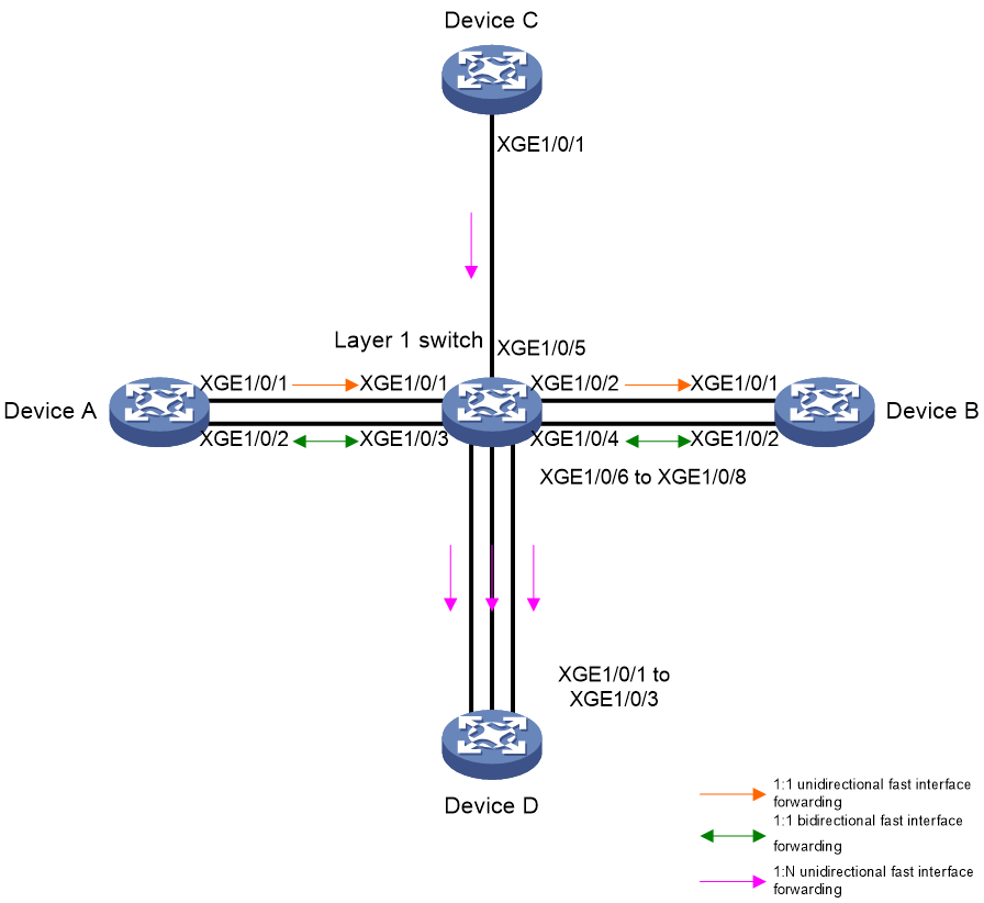
As shown in Figure 8, configure the following functions on the Layer 1 Ethernet switch:
· 1:1 unidirectional fast interface forwarding—XGE 1/0/1 acts as a source interface, XGE 1/0/2 acts as a destination interface, and XGE 1/0/1 only forwards received packets to XGE 1/0/2.
· 1:1 bidirectional fast interface forwarding—XGE 1/0/3 and XGE 1/0/4 act as source and destination interfaces for each other. Any packet received on XGE 1/0/3 is forwarded to XGE 1/0/4, and any packet received on XGE 1/0/4 is forwarded to XGE 1/0/3.
· 1: N unidirectional fast interface forwarding—XGE 1/0/5 acts as a source interface and XGE 1/0/6 through XGE 1/0/8 act as destination interfaces. When XGE 1/0/5 receives a packet, it forwards a copy of the packet to XGE 1/0/6 through XGE 1/0/8 separately.
Configuring 1:1 unidirectional fast interface forwarding
# Specify XGE 1/0/1 as a source interface on XGE 1/0/2, . Alternatively, specify XGE 1/0/2 as a destination interface on XGE 1/0/1.
<L1> system-view
[L1] interface Ten-GigabitEthernet 1/0/2
[L1-Ten-GigabitEthernet1/0/2] source-interface Ten-GigabitEthernet 1/0/1
[L1-Ten-GigabitEthernet1/0/2] quit
[L1] interface Ten-GigabitEthernet 1/0/1
[L1-Ten-GigabitEthernet1/0/1] destination-interface Ten-GigabitEthernet 1/0/2
[L1-Ten-GigabitEthernet1/0/1] quit
Configuring 1:1 bidirectional fast interface forwarding
# Connect a pair of interfaces XGE 1/03 and XGE 1/0/4.
<L1> system-view
[L1] connection-interface Ten-GigabitEthernet 1/0/3 Ten-GigabitEthernet 1/0/4
Configuring 1: N unidirectional fast interface forwarding
# Specify XGE 1/0/6 through XGE 1/0/8 as destination interfaces on XGE 1/0/5.
<L1> system-view
[L1] interface Ten-GigabitEthernet 1/0/5
[L1-Ten-GigabitEthernet1/0/5] destination-interface Ten-GigabitEthernet 1/0/6 to Ten-GigabitEthernet 1/0/8
[L1-Ten-GigabitEthernet1/0/5] quit
Verifying the configuration
# Display interconnection information of interfaces to see the connection relationships among interfaces.
[L1] display interface connection
Connection(s):
XGE1/0/1 --> XGE1/0/2
XGE1/0/2 <-- XGE1/0/1
XGE1/0/3 <-> XGE1/0/4
XGE1/0/4 <-> XGE1/0/3
XGE1/0/5 --> XGE1/0/6
--> XGE1/0/7
--> XGE1/0/8
XGE1/0/6 <-- XGE1/0/5
XGE1/0/7 <-- XGE1/0/5
XGE1/0/8 <-- XGE1/0/5
Example: Configuring a Layer 1.5 Ethernet switch
Network configuration
As shown in Figure 9, deploy a FastMux group on the Layer 1.5 Ethernet switch to implement N:1 packet forwarding. XGE 1/0/1 acts as an upstream interface, and XGE 1/0/2 through XGE 1/0/4 act as downstream interfaces. Packets received on multiple downstream interfaces can be aggregated on the upstream interface for forwarding.

Procedure
# Create a FastMux group and enter its view.
<Layer 1.5> system-view
[L1.5] fast-mux 1 type 1 fpga 0
# Assign an upstream interface to the FastMux group.
[L1.5-fast-mux-group-1-fpga-0] upstream-port Ten-GigabitEthernet 1/0/1
# Assign downstream interfaces to the FastMux group.
[L1.5-fast-mux-group-1-fpga-0] downstream-port Ten-GigabitEthernet 1/0/2 to Ten-GigabitEthernet 1/0/4
[L1.5-fast-mux-group-1-fpga-0] quit
# Configure a reverse L1 connection.
[L1.5]interface range Ten-GigabitEthernet 1/0/2 to Ten-GigabitEthernet 1/0/4
[L1.5-if-range] source-interface Ten-GigabitEthernet 1/0/1
[L1.5-if-range] quit
Verifying the configuration
# Display the FastMux group information.
[L1.5] display mux mode fast-mux
Fast multiplex group 1 fpga 0 (7:1):
Upstream interface: Ten-GigabitEthernet1/0/1
Active Downstream interfaces: Ten-GigabitEthernet1/0/2 to Ten-GigabitEthernet1/0/4
Example: Configuring SecurityMux on a Layer 1.5 Ethernet switch
Network configuration
As shown in Figure 10, deploy Mux and Demux groups on the Layer 1.5 Ethernet switch to implement 1:N and N:1 bidirectional packet forwarding.
· In the Mux group, XGE 1/0/1 acts as an upstream interface, and XGE 1/0/2 through XGE 1/0/4 act as downstream interfaces. Packets received on multiple downstream interfaces can be aggregated on the upstream interface for forwarding.
· In the Demux group, XGE 1/0/1 acts as a downstream interface, and XGE 1/0/2 through XGE 1/0/4 act as upstream interfaces. Packets received on one downstream interface can be distributed to all upstream interfaces for forwarding.

Procedure
# Create a Mux group and enter its view.
<Layer 1.5> system-view
[L1.5] mux 1 fpga 0
# Assign an upstream interface to the Mux group.
[L1.5-mux-group-1-fpga-0] upstream-port Ten-GigabitEthernet 1/0/1
# Assign downstream interfaces to the Mux group.
[L1.5-mux-group-1-fpga-0] downstream-port Ten-GigabitEthernet 1/0/2 to Ten-GigabitEthernet 1/0/4
[L1.5-mux-group-1-fpga-0] quit
# Create a Demux group and enter its view.
<L1.5> system-view
[L1.5] demux 1 fpga 0
# Assign an upstream interface to the Demux group.
[L1.5-demux-group-1-fpga-0] upstream-port Ten-GigabitEthernet 1/0/2 to Ten-GigabitEthernet 1/0/4
# Assign downstream interfaces to the Demux group.
[L1.5-demux-group-1-fpga-0] downstream-port Ten-GigabitEthernet 1/0/1
[L1.5-demux-group-1-fpga-0] quit
Verifying the configuration
# Display information of Mux and Demux groups.
[L1.5] display mux
Multiplex group 1 fpga 0:
Upstream interface: Ten-GigabitEthernet1/0/1
Downstream interfaces: Ten-GigabitEthernet1/0/2 to Ten-GigabitEthernet1/0/4
Demultiplex group 1 fpga 0:
Downstream interface: Ten-GigabitEthernet1/0/1
Upstream interfaces: Ten-GigabitEthernet1/0/2 to Ten-GigabitEthernet1/0/4
