- Table of Contents
- Related Documents
-
| Title | Size | Download |
|---|---|---|
| 02-Installing the device | 1.95 MB |
Contents
Confirming installation preparations
Mounting the device on a workbench
Installing the device in a 19-inch rack
Installing the device by using front and rear mounting brackets
Installing the device by using front mounting brackets and a rack shelf
Installing the device by using front mounting brackets and slide rails
(Optional) Installing network port lightning protectors
(Optional) Installing a surge protected power strip
Installing an expansion module
Installing an expansion module on the front panel
Installing an expansion module on the rear panel
Connecting an Ethernet copper port
Installing the device
|
|
WARNING! Keep the tamper-proof seal on a mounting screw on the chassis cover intact, and if you want to open the chassis, contact H3C Support for permission. Otherwise, H3C shall not be liable for any consequence caused thereby. |
Confirming installation preparations
Before you install the device, verify that you have read "Preparing for installation" carefully and the installation site meets all the requirements.
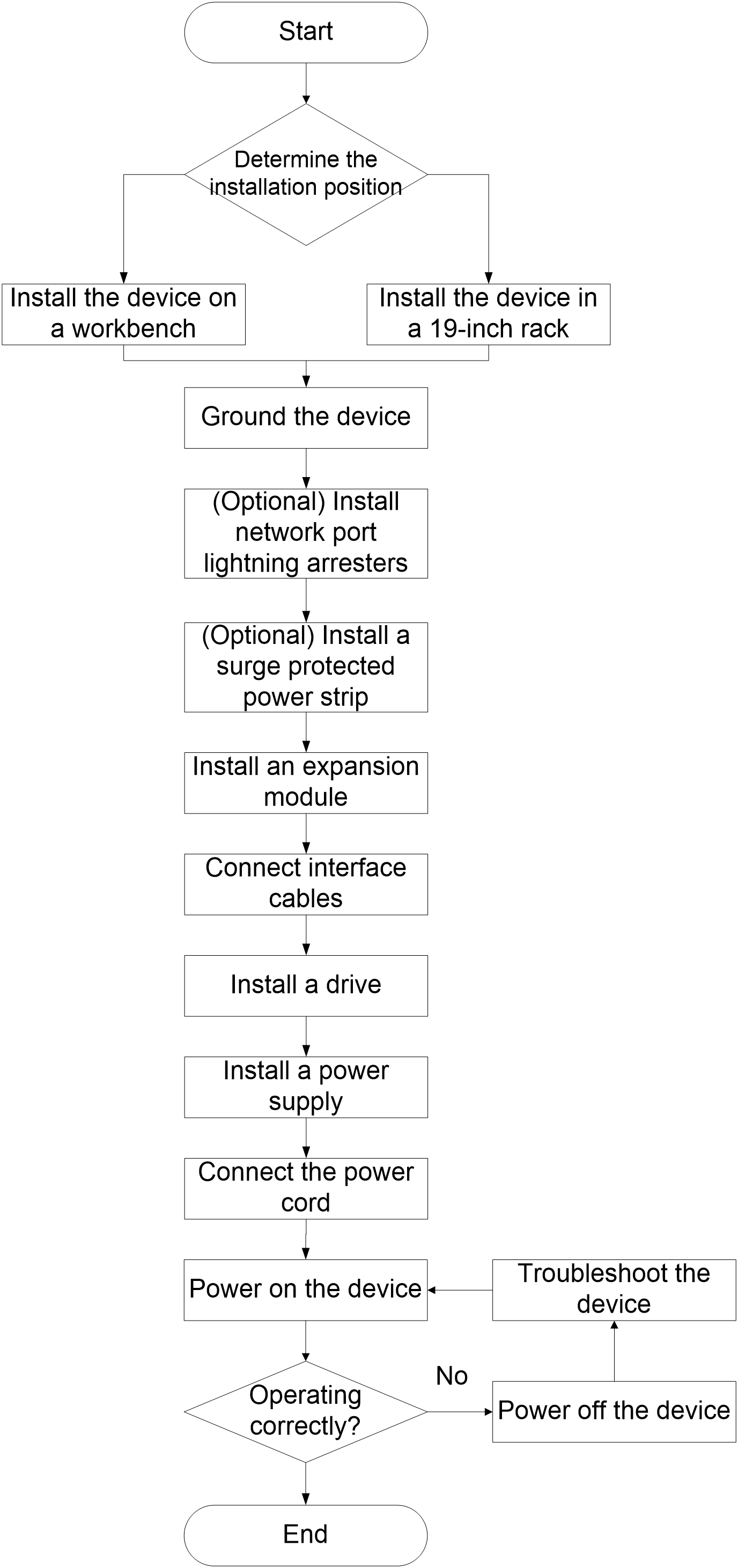
Installation flowchart
Figure2-1 Installation flowchart
Mounting the device on a workbench
|
|
CAUTION: Do not place heavy objects on the device. |
If a standard 19-inch rack is not available, you can mount the device on an anti-static workbench in the equipment room.
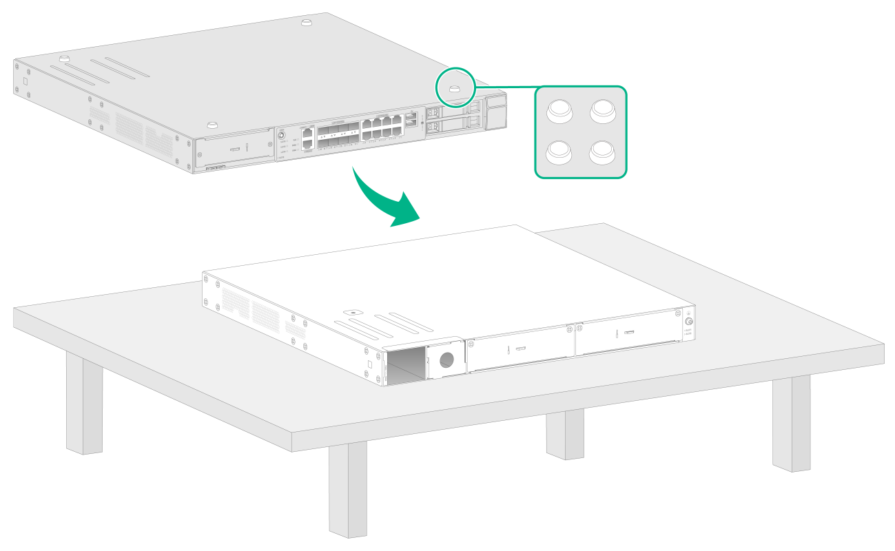
To mount the device on a workbench:
1. Place the device upside down. Clean the recessed areas on the chassis bottom.
2. Attach the four rubber feet to the recessed areas on the chassis bottom.
3. Place the device on the workbench with the upside up. Make sure the four rubber feet stand firmly on the workbench.
Figure2-2 Mounting the device on a workbench
Installing the device in a 19-inch rack
|
|
IMPORTANT: Keep a minimum distance of 1 U (44.45 mm, or 1.75 in) between devices in a rack for good heat dissipation. |
You can install the device in a 19-inch rack by using the following methods:
· Installing the device by using front and rear mounting brackets.
· Installing the device by using front mounting brackets and a rack shelf.
· Installing the device by using front mounting brackets and slide rails.
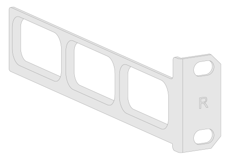
Mounting brackets
Figure2-3 Front mounting bracket
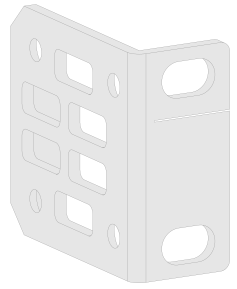
Figure2-4 Rear mounting bracket
Installing the device by using front and rear mounting brackets
1. Wear the ESD wrist strap and make sure the rack is sturdy and is reliably grounded.
2. Use a front mounting bracket to mark the cage nut installation position on the front rack posts. Install cage nuts.
Figure2-5 Installing cage nuts
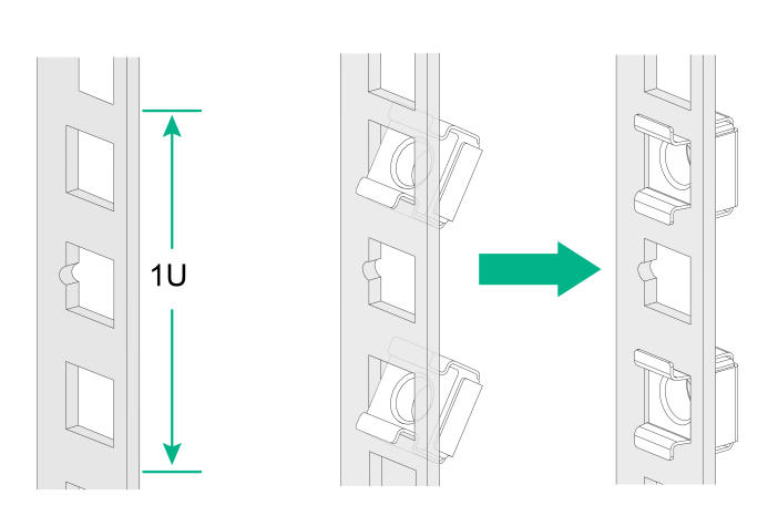
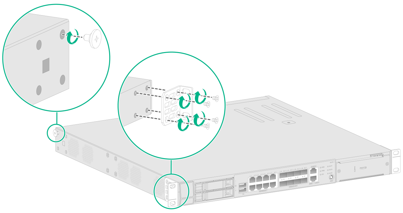
3. Use the M3 screws supplied with the front mounting brackets to secure the front mounting brackets to both sides of the device. Attach the shoulder screws supplied with the rear mounting brackets to both sides of the device.
The shoulder screws will be in close contact with the rear mounting brackets to support the device.
Figure2-6 Attaching the front mounting brackets to the device
4. According to the device installation position in the rack, use screws and cage nuts to attach the rear mounting brackets to the rear rack posts.
Figure2-7 Installing rear mounting brackets

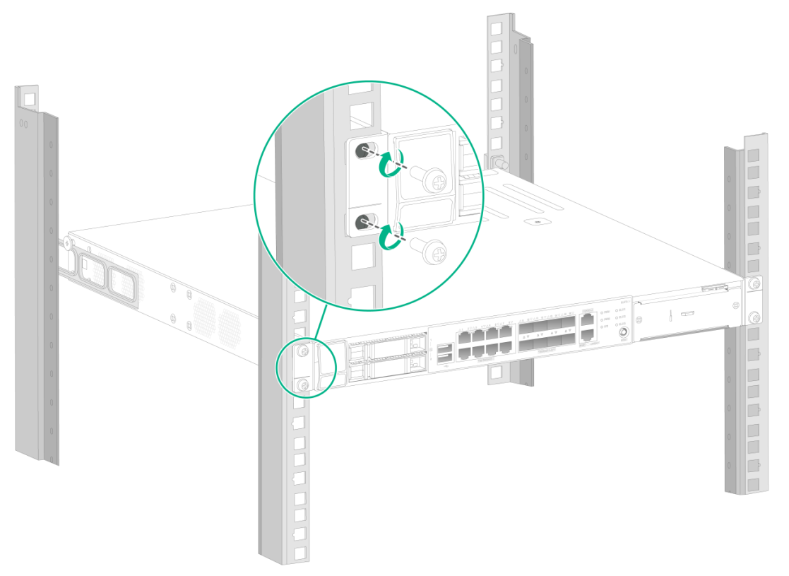
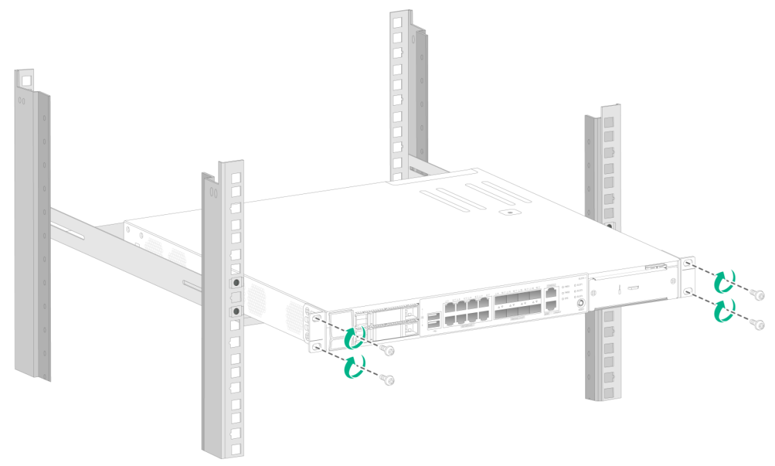
5. Supporting the bottom of the device with one hand and holding the front of the device with the other, place the device slowly in the rack. Attach the front mounting brackets on the device to the front rack posts with screws and cage nuts, as shown in Figure2-8. Make sure the load-bearing screws are in close contact with the upper edges of the rear mounting brackets.
Figure2-8 Installing the device in the rack
Installing the device by using front mounting brackets and a rack shelf
The rack shelf is an optional component that needs to be separately ordered if needed. The rack shelf in this example is for illustration only.
To install the device by using front mounting brackets and a rack shelf:
1. Wear the ESD wrist strap and verify that the rack is sturdy and is reliably grounded.
2. Use the M3 screws supplied with the front mounting brackets to attach the front mounting brackets to the device, as shown in Figure2-6.
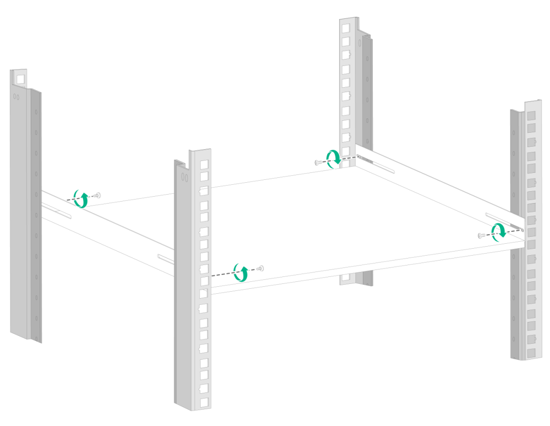
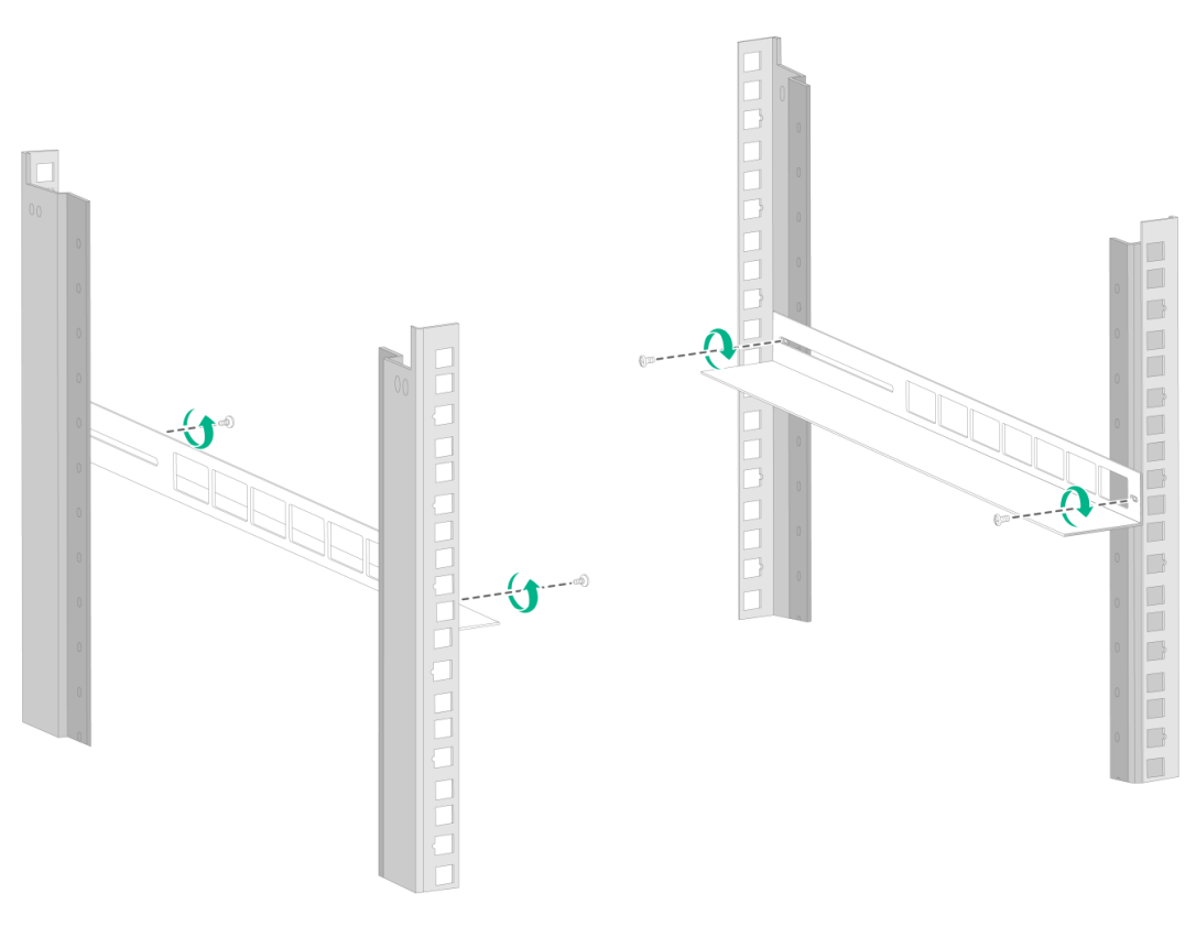
3. Attach the rack shelf to the desired position in the rack. See Figure2-9 for reference.
Figure2-9 Installing the rack shelf
4. Place the device on the rack shelf and push the device in the rack. Attach the front mounting brackets on the device to the front rack posts by using M6 screws and cage nuts, as shown in Figure2-10.
Figure2-10 Installing the device in the rack
Installing the device by using front mounting brackets and slide rails
The slide rails are optional components that need to be separately ordered if needed. The slide rails in this example are for illustration only.
To install the device by using front mounting brackets and slide rails:
1. Wear the ESD wrist strap and verify that the rack is sturdy and is reliably grounded.
2. Use the screws supplied with the front mounting brackets to attach the front mounting brackets to the device, as shown in Figure2-6.
3. Attach the slide rails to the rack. See Figure2-11 for reference.
Figure2-11 Installing slide rails
4. Holding both sides of the device, push the device in the rack along the slide rails, as shown in Figure2-12. Make sure the chassis bottom makes close contact with the bottom flanges of the slide rails.
Figure2-12 Installing the device in the rack

5. Attach the front mounting brackets on the device to the front rack posts with M6 screws and cage nuts.
Grounding the device
|
|
WARNING! · Correctly connecting the grounding cable is crucial to lightning protection and EMI protection. Before installing or using the device, connect the grounding cable for it correctly. · Connect the grounding cable to the grounding system in the equipment room. Do not connect it to a fire main or lightning rod. |
To ground the device:
1. Use a Phillips screwdriver to remove the grounding screw from the chassis rear panel.
2. Use the grounding screw to attach a ring terminal of the grounding cable to the chassis.
3. Use one of the following methods to connect the other end of the grounding cable:
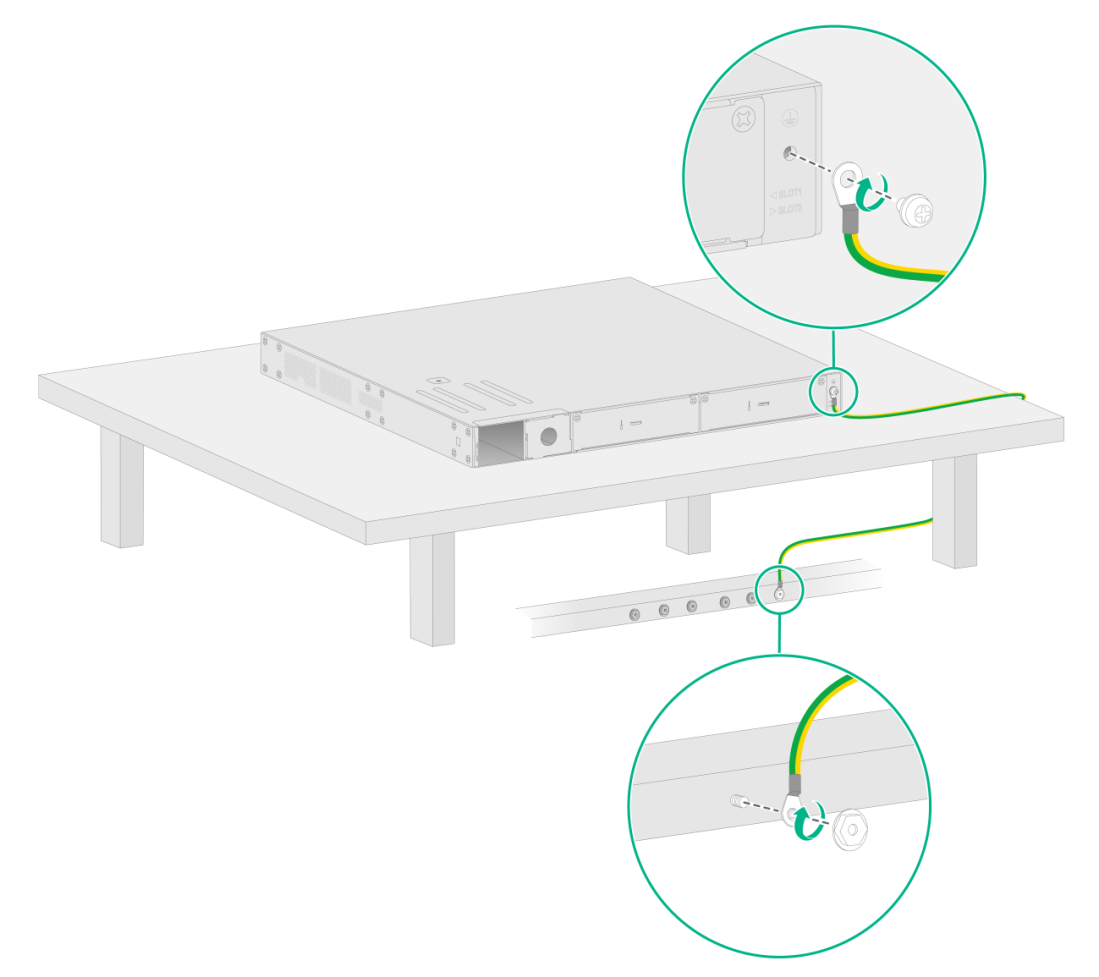
¡ Grounding the device by using a grounding strip
If a grounding strip is available, you can connect the other end of the grounding cable to the grounding strip. Make sure the grounding strip is grounded reliably.
Figure2-13 Grounding the device by using a grounding strip
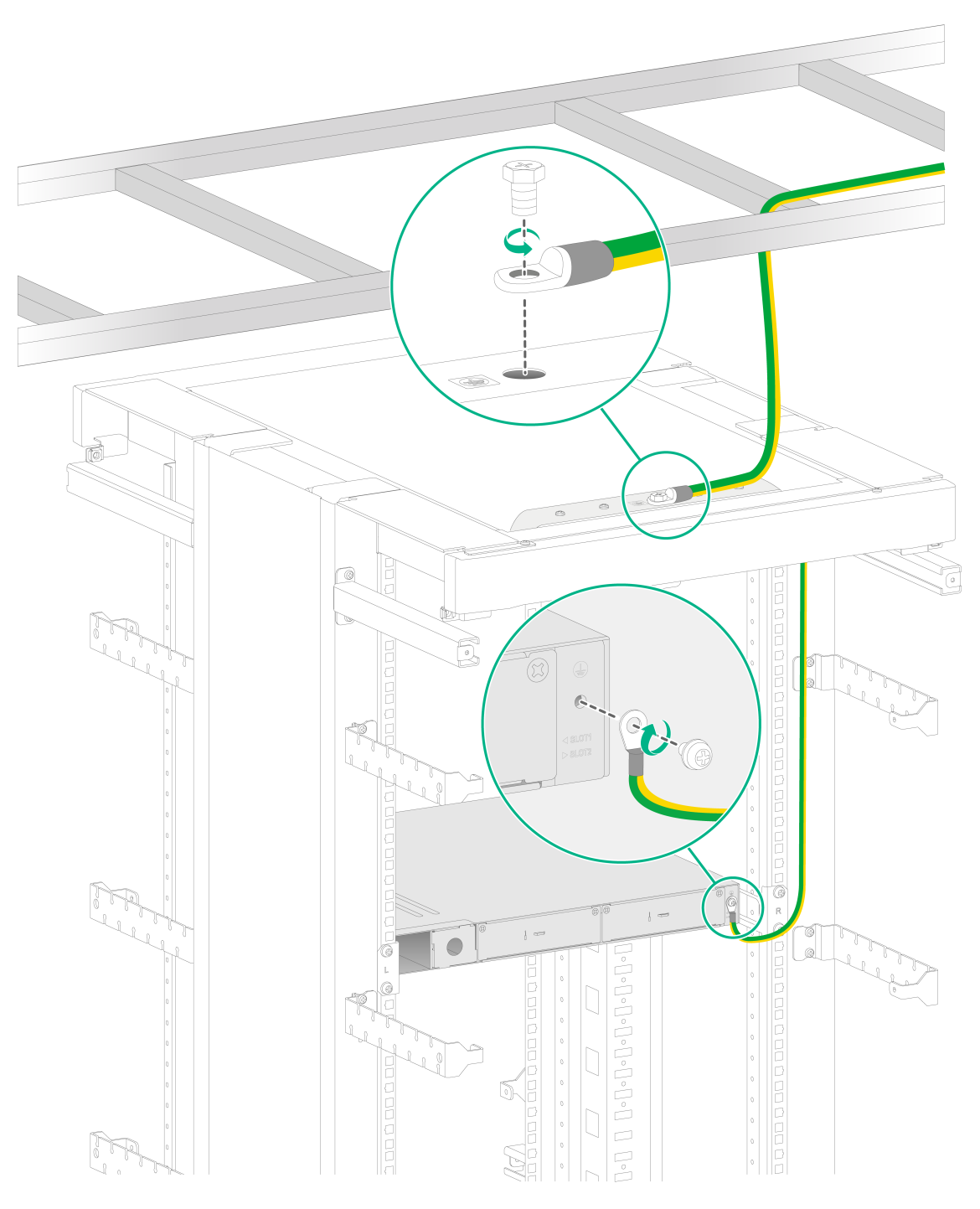
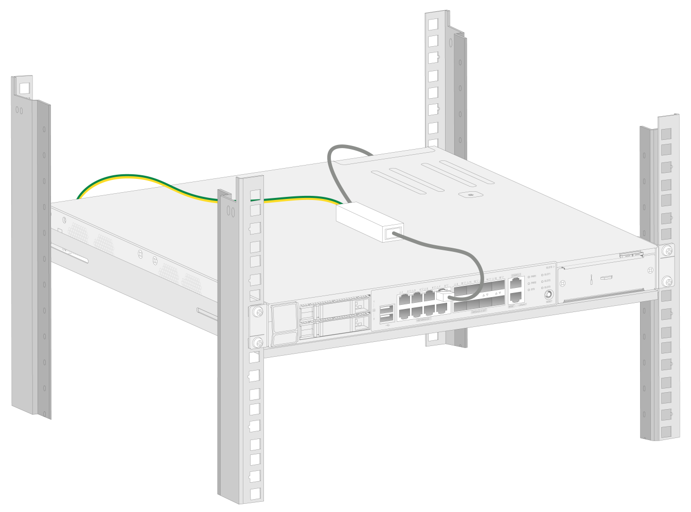
¡ Grounding the device through the rack
If the device is installed in a rack, you can connect the other end of the grounding cable to the grounding point on the rack. Make sure the rack is grounded reliably.
Figure2-14 Grounding the device through the rack
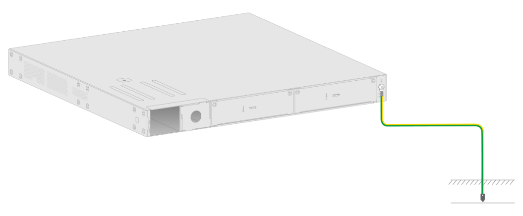
¡ Grounding the device with a grounding conductor buried in the earth
If earth is available at the installation site, you can ground the device with a grounding conductor buried in the earth.
Hammer a 0.5 m (1.64 ft) or longer angle iron or steel tube into the earth to serve as a grounding conductor. Weld the yellow-green grounding cable to the angel iron or steel tube and treat the joint for corrosion protection.
Figure2-15 Grounding the device by burying the grounding conductor into the earth
(Optional) Installing network port lightning protectors
|
|
CAUTION: If part of the network cable for a network port is routed outdoors, install a network port lightning protector for the port to protect against damages caused by lightning strikes. |
|
|
IMPORTANT: · Before installing a network port lightning protector, read the instructions in the document that comes with the protector. · Network port lightning protectors are available only for 10/100M/1000M RJ-45 Ethernet copper ports. · If multiple network ports have network cables routed outdoors, install a network port lightning protector for each network port. |
No network port lightning protectors are provided with the device. Purchase them yourself as required.
To install a network port lightning protector for a network port:
1. Use a double-faced adhesive tape to stick the network port lightning protector onto the device chassis, and make sure it is as close to the grounding screw of the device as possible.
2. Cut the ground wire of the protector to a length (as short as possible) as required by the distance between the protector and the grounding screw of the device. Attach the ground wire securely to the grounding screw of the device.
Make sure the grounding screw of the device is grounded reliably.
3. Use a multimeter to verify that the ground wire of the protector makes good contact with the grounding screw of the chassis.
4. Insert the outdoor network cable into the protector's Surge end marked IN, and insert the cable from the network port into the Protect end marked OUT.
5. Examine the port LED to verify that the port is operating correctly.
Figure2-16 Installing a lightning protector for a network port
(Optional) Installing a surge protected power strip
|
|
CAUTION: If you use an AC power line routed from outdoors for the device, use a surge protected power strip for the device to protect against damages caused by lightning strikes. |
|
|
IMPORTANT: Before installing a surge protected power strip, read the instructions in the document that comes with the strip. |
No surge protected power strip is provided with the device. Purchase one yourself as required.
To use a surge protected power strip, first connect the AC power line routed from outdoors to the strip and then connect the power cord from the device to the strip.
You can attach the surge protected power strip to the rack, workbench, or wall of the equipment room.
Installing an expansion module
|
|
CAUTION: Do not hot swap expansion modules. |
The device does not come with any expansion modules. Purchase expansion modules as needed.
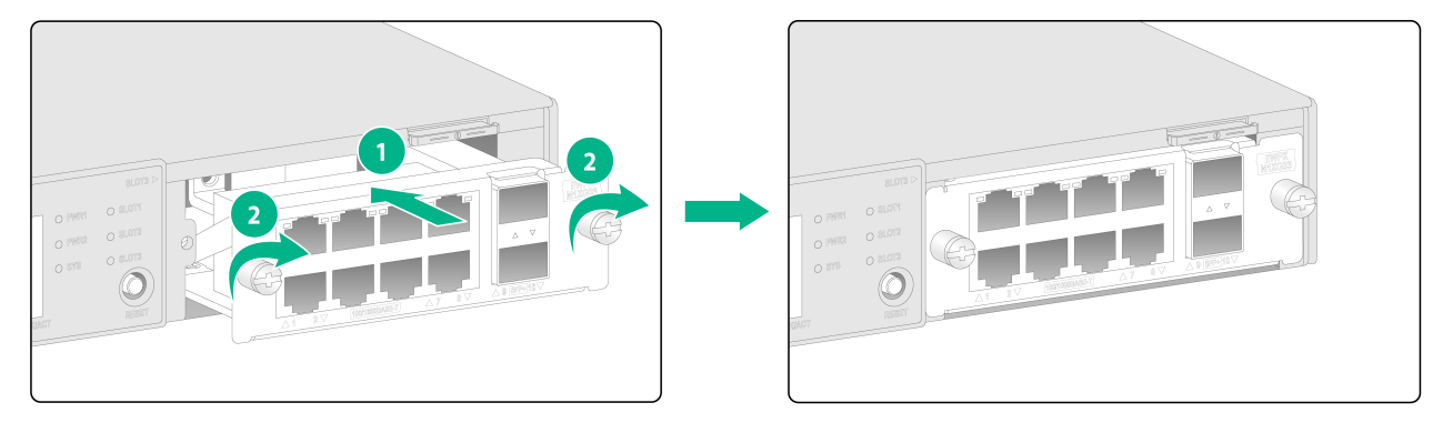
Installing an expansion module on the front panel
You can install EWPXM1XG03 expansion modules in slot 3 in the front panel.
To install an expansion module:
1. Use a Phillips screwdriver to remove the fastening screws on the filler panel in the expansion module slot and remove the filler panel.
2. Insert the expansion module slowly into the slot along the guide rails.
3. Press the expansion module inward until it has close contact with the backplane. Then fasten the captive screws to secure the expansion module to the device.
Figure2-17 Installing an expansion module
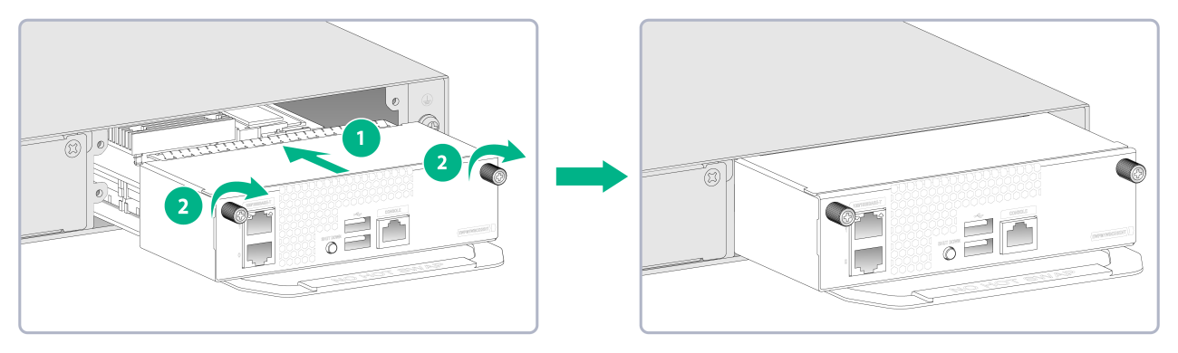
Installing an expansion module on the rear panel
You can install EWPM1WBCE0ENT expansion modules in slot 1 or slot 2 in the rear panel.
To install an expansion module:
1. Use a Phillips screwdriver to remove the screws on the filler panel and then remove the filler panel.
Keep the filler panel for future use.
2. Slide the module slowly into the slot along the guide rails until it makes close contact with the backplane.
3. Use a Phillips screwdriver to fasten the captive screws on the module.
Figure2-18 Installing an expansion module
Connecting interface cables
Connecting an Ethernet copper port
1. Connect one end of the Ethernet cable to the Ethernet copper port on the device, and the other end to the Ethernet port on the peer device.
2. After powering on the device, examine the LEDs of the fixed Ethernet copper port.
For more information about the LED description, see "H3C WX3800X Series Access Controllers Hardware Information and Specifications".
Connecting a fiber port
|
|
WARNING! Do not stare into any open apertures of operating transceiver modules or optical fiber connectors. The laser light emitted from these apertures might hurt your eyes. |
|
|
CAUTION: · To connect a fiber port by using an optical fiber, first install a transceiver module in the port and then connect the optical fiber to the transceiver module. · Insert a dust cap into any open optical fiber connector and a dust plug into any open fiber port or transceiver module port to protect them from contamination and ESD damage. · Never bend an optical fiber excessively. The bend radius of an optical fiber must be not less than 10 cm (3.94 in). · Keep the fiber end clean. · Make sure the Tx and Rx ports on a transceiver module are connected to the Rx and Tx ports on the peer end, respectively. |
No transceiver modules are provided with the device. Purchase transceiver modules yourself as required. For more information about the transceiver modules, see "H3C WX3800X Series Access Controllers Hardware Information and Specifications".
The fiber ports on the device support only LC connectors.
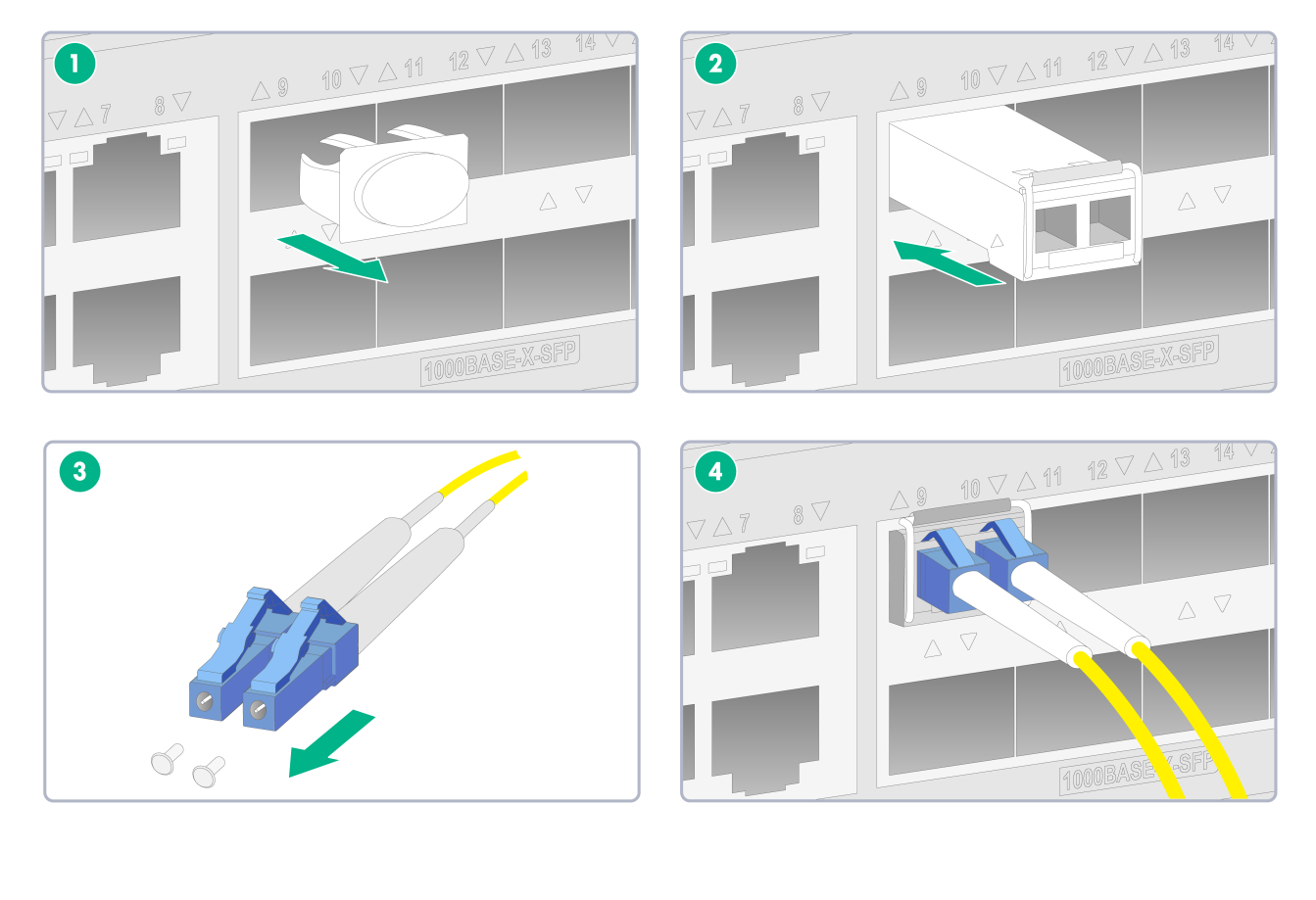
To connect an optical fiber for a fiber port:
1. Remove the dust plug from the fiber port.
2. Pivot the bail latch of the transceiver module up so that it catches a knob on the top of the transceiver module.
3. Holding both sides of the transceiver module, insert the transceiver module slowly into the port.
4. Identify the Rx and Tx ports on the transceiver module and remove the dust caps from the optical fiber connectors. Use the optical fiber to connect the Rx port and Tx port on the transceiver module to the Tx port and Rx port on the peer end, respectively.
5. Examine the port LEDs:
¡ If the LED is on, a fiber link has been set up.
¡ If the LED is off, the link has not been set up. The reason might be wrong connection of the Tx and Rx ends. Swap the fiber connectors in the Tx and Rx ports at one end of the fiber.
Figure2-19 Connecting an optical fiber
Installing a drive
|
|
CAUTION: Do not hot swap drives. |
The device does not come with any drives. Purchase drives as needed.
To install a drive:
1. Wear an ESD wrist strap and make sure it makes good skin contact and is reliably grounded.
2. Remove the filler panel from the drive slot.
3. Press the button on the drive panel to release the locking lever.
4. Hold the locking lever and push the drive into the slot slowly along the guide rails. Then close the locking lever.
Figure2-20 Installing a drive

Installing a power supply
|
|
CAUTION: Do not install an AC power supply and a DC power supply on the same device. |
1. Remove the filler panel (if any) from the slot where you want to install a power supply with a Phillips screwdriver.
Keep the remove filler panel for future use.
2. Holding the handle of the power supply with one hand and supporting the bottom of the power supply with another hand, push the power supply into the slot along the guide rails until the power supply is completely inserted.
3. Use a Phillips screwdriver to fasten the captive screws on the power supply.
Figure2-21 Installing an AC power supply
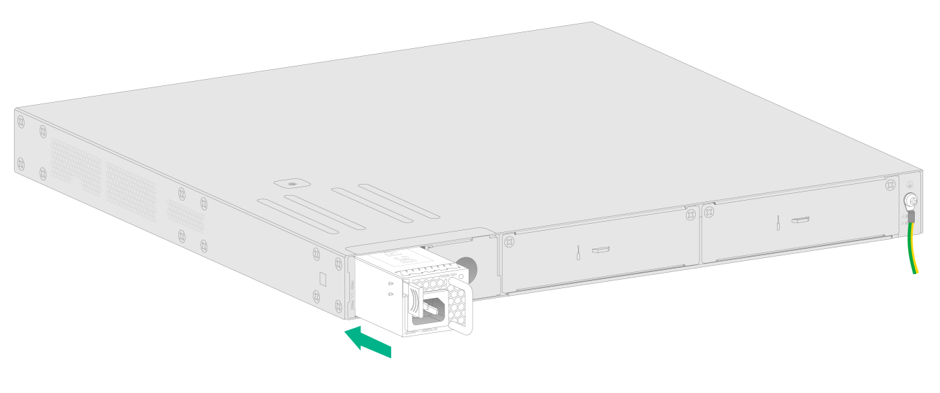
Figure2-22 Installing a DC power supply

Connecting the power cord
|
|
WARNING! To avoid bodily injury, first connect the power cord to the device, and then connect the power cord to the power source in the equipment room. |
|
|
CAUTION: Before connecting the power cord, make sure the device is grounded correctly. |
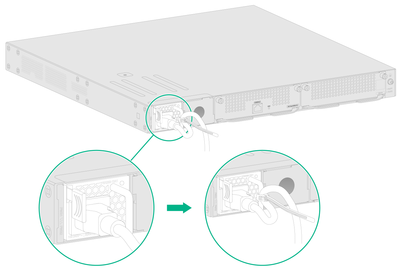
Connecting an AC power cord:
1. Connect one end of the AC power cord to the AC-input power receptacle on the device.
2. Use a cable tie to secure the power cord to the handle of the power supply.
3. Connect the other end of the AC power cord to the AC power source.
Figure2-23 Connecting the power cord
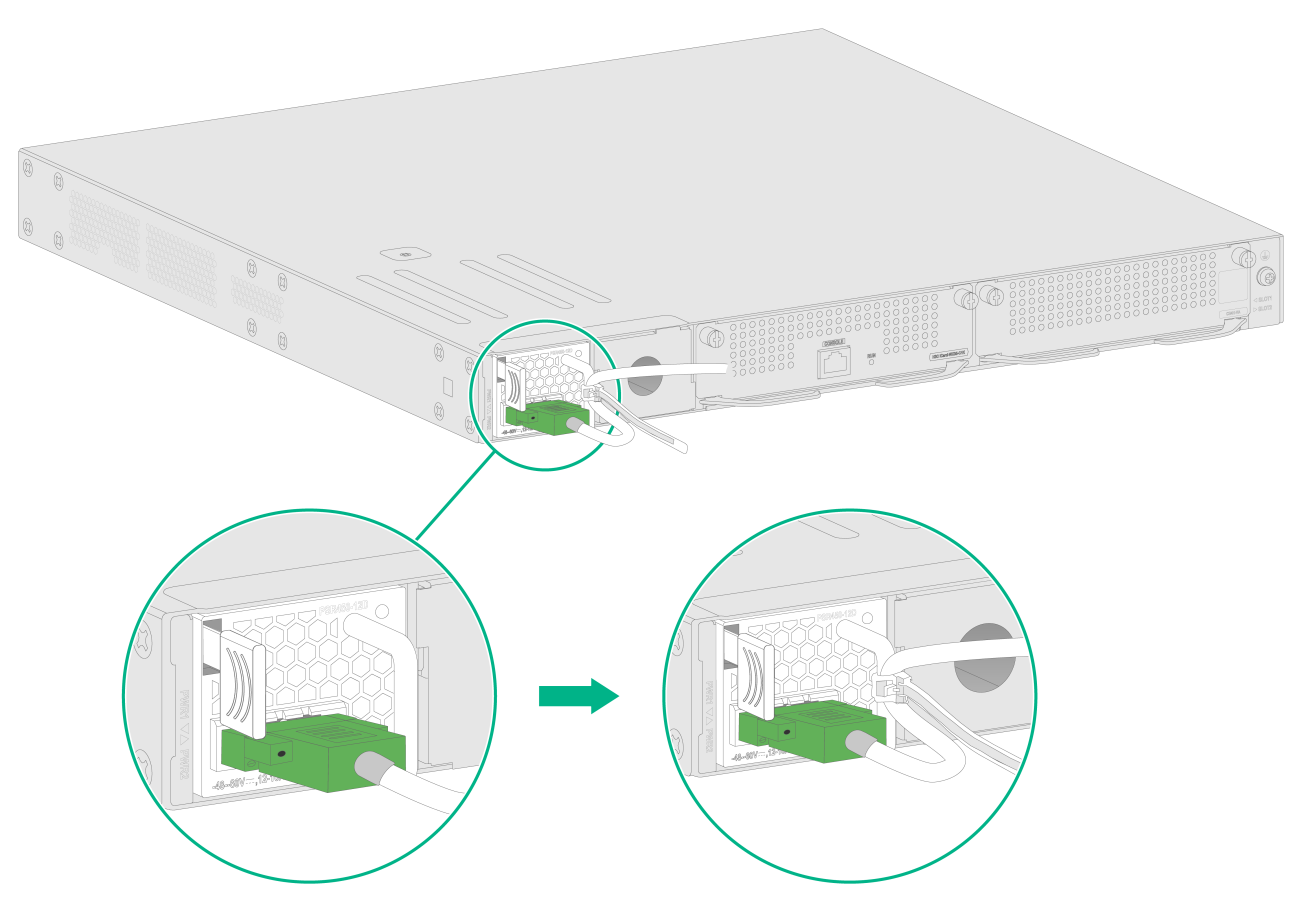
Connecting a DC power cord
1. Use a flat-blade screwdriver to remove the protection cover from the DC power supply.
2. Correctly insert the DC plug into the DC power receptacle.
3. Use a PH0 flat-blade screwdriver to fasten the screws on the DC plug.
4. Connect the other end of the DC power cord to the DC power source.
Figure2-24 Connecting a DC power cord
Verifying the installation
Before powering on the device, verify the following information:
· There is enough space around the device for heat dissipation.
· The work bench is sturdy.
· The grounding cable is securely connected.
· The Ethernet cables, optical fibers, and power cord are connected correctly.
· All the interface cables are cabled indoors. If any cable is routed outdoors, verify that the network port lightning protectors for network ports and surge protected power strip have been installed.
Powering on the device
1. Power on the device. The device initializes its memory and runs the BootWare. The following information appears on the terminal screen:
System is Starting........
Press Ctrl+D to access BASIC-BOOTWARE MENU
Press Ctrl+T to access BOOTWARE DIAG-TEST MENU
Booting Normal Extend Bootware
****************************************************************************
* *
* H3C WX3820X BootWare, Version 1.12 *
* *
****************************************************************************
Copyright (c) 2004-2022 New H3C Technologies Co., Ltd.
Compiled Date : Jun 21 2022
Memory Type : DDR4 SDRAM
Memory Size : 16384MB
Memory Speed : 2133MHz
flash Size : 7456MB
CPLD 1 Version : 1.0
CPLD 2 Version : 6.0
PCB 1 Version : Ver.A
PCB 2 Version : Ver.A
BootWare Validating...
2. Press Ctrl + B at the prompt within 4 seconds to access the Boot menu.
To access the Boot menu after the system enters the system image file reading and self-compressing process, restart the device.
Loading the main image files...
Loading file flash:/system.bin............Done.
Loading file flash:/boot.bin.........Done.
Image file flash:/boot.bin is self-decompressing............................
...........................Done.
System image is starting...
...
Line con0 is available.
Press ENTER to get started.
3. Press Enter at the prompt, and you can configure the device when the prompt <H3C> appears.
|
|
NOTE: If a new CPLD version is available, the device updates its CPLD version automatically. |
