- Table of Contents
-
- 07-Security Configuration Guide
- 00-Preface
- 01-Security Overview
- 02-AAA Configuration
- 03-802.1X Configuration
- 04-MAC Authentication Configuration
- 05-Port Security Configuration
- 06-Public Key Configuration
- 07-PKI Configuration
- 08-SSH Configuration
- 09-SSL Configuration
- 10-User Isolation Configuration
- 11-Portal Configuration
- 12-IPsec Configuration
- Related Documents
-
| Title | Size | Download |
|---|---|---|
| 11-Portal Configuration | 294.30 KB |
Configuring portal authentication
Layer 3 portal authentication process
MAC-based quick portal authentication
Portal configuration task list
Enabling portal authentication
Enabling Layer 3 portal authentication
Controlling access of portal users
Configuring a portal-free rule
Configuring an authentication source subnet
Setting the maximum number of online portal users
Specifying a portal authentication domain
Configuring RADIUS related attributes
Specifying the NAS ID value carried in a RADIUS request
Specifying NAS-Port-Type for an interface
Specifying the NAS-Port-ID for an interface
Specifying a NAS ID profile for an interface
Specifying a source IP address for outgoing portal packets
Specifying a device ID to be sent to a portal client
Configuring MAC-based quick portal authentication
Specifying an autoredirection URL for authenticated portal users
Configuring portal detection functions
Configuring online Layer 3 portal user detection
Configuring the portal server detection function
Configuring portal user information synchronization
Configuring mandatory webpage pushing
Specifying the parameters carried in the redirection URL
Configuring a redirection URL based on a user-requested URL
Configuring Web redirect track
Enabling host identity check through DHCP snooping entries or WLAN binding entries
Displaying and maintaining portal
Inconsistent keys on the access device and the portal server
Incorrect server port number on the access device
Overview
With portal authentication, an access device redirects all users to the portal authentication page. All users can access the free services provided on the portal website. However, to access the Internet, a user must pass portal authentication.
A user can access a known portal website and enter a username and password for authentication. This authentication mode is called active authentication. There is another authentication mode, forced authentication, in which the access device forces a user who is trying to access the Internet through HTTP to log on to a portal website for authentication.
The portal feature provides the flexibility for ISPs to manage services. A portal website can, for example, present advertisements and deliver community and personalized services. In this way, broadband network providers, equipment vendors, and content service providers form an industrial ecological system.
Extended portal functions
By forcing patching and anti-virus policies, extended portal functions help users to defend against viruses. Portal authentication supports the following extended functions:
· Security check—Works after identity authentication succeeds to check whether the required anti-virus software, virus definition file, and operating system patches are installed, and whether there is any unauthorized software installed on the user host.
· Resource access restriction—Allows users passing identity authentication to access only network resources in the quarantined area, such as the anti-virus server and the patch server. Only users passing both identity authentication and security check can access restricted network resources.
Portal system components
A typical portal system comprises these basic components: authentication client, access device, portal server, authentication/accounting server, and security policy server.
Figure 1 Portal system components
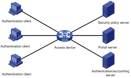
Authentication client
An authentication client is an entity seeking access to network resources. It is typically an end-user terminal such as a PC. A client can use a browser or portal client software for portal authentication. Client security check is implemented through communications between the client and the security policy server.
To implement security check, the client must be the H3C iNode client.
Access device
Access devices control user access. An access device can be a switch or router that provides the following functions:
· Redirecting all HTTP requests from unauthenticated users to the portal server.
· Interacting with the portal server, the security policy server, and the authentication/accounting server for identity authentication, security check, and accounting.
· Allowing users who have passed identity authentication and security check to access granted Internet resources.
Portal server
A portal server listens to authentication requests from authentication clients and exchanges client authentication information with the access device. It provides free portal services and pushes Web authentication pages to users.
Authentication/accounting server
An authentication/accounting server implements user authentication and accounting through interaction with the access device.
Only a RADIUS server can serve as the remote authentication/accounting server in a portal system.
Security policy server
A security policy server interacts with authentication clients and access devices for security check and resource authorization.
The components of a portal system interact as follows:
1. When an unauthenticated user enters a website address in the browser's address bar to access the Internet, an HTTP request is created and sent to the access device. The access device then redirects the HTTP request to the portal server's Web authentication homepage. For extended portal functions, authentication clients must run the portal client software.
2. On the authentication homepage/authentication dialog box, the user enters and submits the authentication information, which the portal server then transfers to the access device.
3. Upon receipt of the authentication information, the access device communicates with the authentication/accounting server for authentication and accounting.
4. After successful authentication, the access device checks whether there is a corresponding security policy for the user. If not, it allows the user to access the Internet. Otherwise, the client communicates with the access device and the security policy server for security check. If the client passes security check, the security policy server authorizes the user to access the Internet resources.
|
|
NOTE: Portal authentication supports NAT traversal whether it is initiated by a Web client or an H3C iNode client. When the portal authentication client is on a private network, but the portal server is on a public network and the access device is enabled with NAT, network address translations performed on the access device do not affect portal authentication. However, in such a case, H3C recommends using an interface's public IP address as the source address of outgoing portal packets. |
Portal authentication modes
Only Layer 3 portal authentication is supported in the current software version.
You can enable Layer 3 portal authentication on an access device's Layer 3 interfaces that connect authentication clients. Portal authentication performed on a Layer 3 interface can be direct authentication, re-DHCP authentication, or cross-subnet authentication. In direct authentication and re-DHCP authentication, no Layer 3 forwarding devices exist between the authentication client and the access device. In cross-subnet authentication, Layer 3 forwarding devices may exist between the authentication client and the access device.
· Direct authentication
Before authentication, a user manually configures a public IP address or directly obtains a public IP address through DHCP, and can access only the portal server and predefined free websites. After passing authentication, the user can access the network resources. The process of direct authentication is simpler than that of re-DHCP authentication.
· Re-DHCP authentication
Before authentication, a user gets a private IP address through DHCP and can access only the portal server and predefined free websites. After passing authentication, the user is allocated a public IP address and can access the network resources. No public IP address is allocated to those who fail authentication. This solves the IP address planning and allocation problem. For example, a service provider can allocate public IP addresses to broadband users only when they access networks beyond the residential community network.
IPv6 portal authentication does not support the re-DHCP authentication mode.
Cross-subnet authentication is similar to direct authentication, but it allows Layer 3 forwarding devices to be present between the authentication client and the access device.
In direct authentication, re-DHCP authentication, and cross-subnet authentication, the client's IP address is used for client identification. After a client passes authentication, the access device generates an ACL for the client based on the client's IP address to permit packets from the client to go through the access port. Because no Layer 3 devices are present between the authentication clients and the access device in direct authentication and re-DHCP authentication, the access device can directly learn the clients' MAC addresses, and can enhance the capability of controlling packet forwarding by also using the learned MAC addresses.
Portal support for EAP
Only Layer 3 portal authentication that uses a remote portal server supports EAP authentication.
Authentication by using the username and password is less secure. Digital certificate authentication is usually used to ensure higher security.
The Extensible Authentication Protocol (EAP) supports several digital certificate-based authentication methods, for example, EAP-TLS. Working together with EAP, portal authentication can implement digital certificate-based user authentication.
Figure 2 Portal support for EAP working flow diagram
![]()
As shown in Figure 2, the authentication client and the portal server exchange EAP authentication packets. The portal server and the access device exchange portal authentication packets that carry the EAP-Message attributes. The access device and the RADIUS server exchange RADIUS packets that carry the EAP-Message attributes. The RADIUS server that supports the EAP server function processes the EAP packets encapsulated in the EAP-Message attributes, and provides the EAP authentication result. During the whole EAP authentication process, the access device does not process the packets that carry the EAP-Message attributes but only transports them between the portal server and the RADIUS server. Therefore, no additional configuration is needed on the access device.
|
|
NOTE: To use portal authentication that supports EAP, the portal server and client must be the H3C IMC portal server and the H3C iNode portal client. |
Layer 3 portal authentication process
Direct authentication and cross-subnet authentication share the same authentication process. Re-DHCP authentication has a different process because of the presence of two address allocation procedures.
Direct authentication/cross-subnet authentication process (with CHAP/PAP authentication)
Figure 3 Direct authentication/cross-subnet authentication process
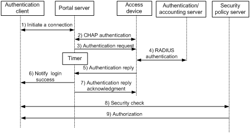
The direct authentication/cross-subnet authentication process is as follows:
1. An authentication client initiates authentication by sending an HTTP request. When the HTTP packet arrives at the access device, the access device allows it to pass if it is destined for the portal server or a predefined free website, or redirects it to the portal server if it is destined for other websites. The portal server pushes a Web authentication page to the user and the user enters the username and password.
2. The portal server and the access device exchange CHAP messages. This step is skipped for PAP authentication.
3. The portal server assembles the username and password into an authentication request message and sends it to the access device. Meanwhile, the portal server starts a timer to wait for an authentication acknowledgment message.
4. The access device and the RADIUS server exchange RADIUS packets to authenticate the user.
5. The access device sends an authentication reply to the portal server.
6. The portal server sends an authentication success message to the authentication client to notify it of logon success.
7. The portal server sends an authentication reply acknowledgment message to the access device.
With extended portal functions, the process includes additional steps:
8. The security policy server exchanges security check information with the authentication client to check whether the authentication client meets the security requirements.
9. Based on the security check result, the security policy server authorizes the user to access certain resources, and sends the authorization information to the access device. The access device then controls access of the user based on the authorization information.
Re-DHCP authentication process (with CHAP/PAP authentication)
Figure 4 Re-DHCP authentication process

The re-DHCP authentication process is as follows:
Step 1 through step 6 are the same as those in the direct authentication/cross-subnet authentication process.
7. After receiving the authentication success message, the authentication client obtains a new public IP address through DHCP and notifies the portal server that it has obtained a public IP address.
8. The portal server notifies the access device that the authentication client has obtained a new public IP address.
9. Detecting the change of the IP address by examining ARP packets received, the access device notifies the portal server of the change.
10. The portal server notifies the authentication client of logon success.
11. The portal server sends a user IP address change acknowledgment message to the access device.
With extended portal functions, the process includes additional steps:
12. The security policy server exchanges security check information with the authentication client to check whether the authentication client meets the security requirements.
13. Based on the security check result, the security policy server authorizes the user to access certain resources, and sends the authorization information to the access device. The access device then controls access of the user based on the authorization information.
Portal support for EAP authentication process
Figure 5 Portal support for EAP authentication process

All portal authentication modes share the same EAP authentication steps. The following example uses direct portal authentication to show the EAP authentication process:
1. The authentication client sends an EAP Request/Identity message to the portal server to initiate an EAP authentication process.
2. The portal server sends a portal authentication request to the access device, and starts a timer to wait for the portal authentication reply. The portal authentication request contains several EAP-Message attributes, which are used to encapsulate the EAP packet sent from the authentication client and carry the certificate information of the client.
3. After the access device receives the portal authentication request, it constructs a RADIUS authentication request and sends it to the RADIUS server. The EAP-Message attributes in the RADIUS authentication request are those carried in the received portal authentication request.
4. The access device sends a certificate request to the portal server according to the reply received from the RADIUS server. The certificate request also contains several EAP-Message attributes, which are used to transfer the certificate information of the RADIUS server. The EAP-Message attributes in the certificate request are those carried in the RADIUS authentication reply.
5. After receiving the certificate request, the portal server sends an EAP authentication reply to the authentication client, carrying the EAP-Message attribute values.
6. The authentication client sends another EAP request to continue the EAP authentication with the RADIUS server, during which there may be several portal authentication requests. The subsequent authentication processes are the same as that initiated by the first EAP request, except that the EAP request types vary with the EAP authentication phases.
7. After the authentication client passes the EAP authentication, the RADIUS server sends an authentication reply to the access device. This reply carries the EAP-Success message in the EAP-Message attribute.
8. The access device sends an authentication reply to the portal server. This reply carries the EAP-Success message in the EAP-Message attribute.
9. The portal server notifies the authentication client of the authentication success.
10. The portal server sends an authentication reply acknowledgment to the access device.
The remaining steps are for extended portal authentication. For more information about the steps, see the portal authentication process with CHAP/PAP authentication.
MAC-based quick portal authentication
Typically, users must provide username and password for portal authentication each time they access the network. Users who access the network frequently may want to pass authentication without entering username and password. To meet such requirements, portal supports a MAC-based quick authentication scheme, which is also referred to as MAC-triggered authentication.
With MAC-triggered authentication, the access device obtains the source MAC address of a user. When the network traffic of the user is below the specified threshold (1024 bytes for example), the access device allows the user to access the network without portal authentication. When the user's network traffic reaches the threshold, the access device triggers portal authentication for the user. The authentication procedure is as follows:
1. The access device sends a MAC binding query to the MAC binding server.
2. When the MAC binding server receives the query, it checks whether the MAC address is bound with a portal user account.
· If yes, the MAC binding server obtains the account information of the portal user, and sends the username and password of the user to the access device to initiate portal authentication. The user can pass portal authentication without entering the username and password.
· If not, the MAC binding server notifies the access device to perform normal portal authentication for the user. The access device redirects the subsequent HTTP packet of the user to the portal server, which provides a portal authentication page for the user. The user must enter the username and password to pass portal authentication.
MAC-triggered authentication provides a quick, effective portal authentication for users whose MAC addresses have been bound with portal user accounts on the MAC binding servers.
|
|
NOTE: A MAC binding server is required for MAC-triggered authentication. A MAC binding server records the MAC-to-account bindings of portal users. Only specific servers can serve as MAC binding servers. |
Portal configuration task list
|
Task |
Remarks |
|
|
Required. |
||
|
Required. |
||
|
Optional. |
||
|
Optional. |
||
|
Optional. |
||
|
Optional. |
||
|
Optional. |
||
|
Specifying an autoredirection URL for authenticated portal users |
Optional. |
|
|
Optional. |
||
|
Optional. |
||
|
Optional. |
||
|
Optional. |
||
|
Optional. |
||
|
Enabling host identity check through DHCP snooping entries or WLAN binding entries |
Optional. |
|
To configure mandatory webpage pushing:
|
Required. You cannot configure both mandatory webpage pushing and portal authentication on the same interface. |
Configuration prerequisites
Although the portal feature provides a solution for user identity authentication and security check, the portal feature cannot implement this solution by itself. RADIUS authentication must be configured on the access device to cooperate with the portal feature to complete user authentication.
The prerequisites for portal authentication configuration are as follows:
· The portal server and the RADIUS server have been installed and configured properly.
· With re-DHCP authentication, the IP address check function of the DHCP relay agent is enabled on the access device, and the DHCP server is installed and configured properly.
· The portal client, access device, and servers can reach each other.
· With RADIUS authentication, usernames and passwords of the users are configured on the RADIUS server, and the RADIUS client configurations are performed on the access device. For information about RADIUS client configuration, see "Configuring AAA."
· To implement extended portal functions, install and configure CAMS EAD or IMC EAD, and make sure that the ACLs configured on the access device correspond to those specified for the resources in the quarantined area and for the restricted resources on the security policy server. For information about security policy server configuration on the access device, see "Configuring AAA."
For installation and configuration about the security policy server, see CAMS EAD Security Policy Component User Manual or IMC EAD Security Policy Help.
The ACL for resources in the quarantined area and that for restricted resources correspond to isolation ACL and security ACL on the security policy server respectively.
You can modify the authorized ACLs on the access device. However, your changes take effect only for portal users logging on after the modification.
For portal authentication to operate properly, make sure the device name is no more than 16 characters.
Specifying the portal server
Perform this task to specify portal server parameters for Layer 3 portal authentication, including the portal server IP address, shared encryption key, server port, and the URL address for Web authentication.
To specify a portal server for Layer 3 authentication:
|
Step |
Command |
Remarks |
|
1. Enter system view. |
system-view |
N/A |
|
2. Specify a portal server and configure related parameters. |
portal server server-name ip ip-address [ key [ cipher | simple ] key-string | port port-id | server-type { cmcc | imc } | url url-string ] * | ipv6 ipv6-address [ key [ cipher | simple ] key-string | port port-id | url url-string ] * } |
By default, no portal server is specified. |
|
|
NOTE: The specified parameters of a portal server can be modified or deleted only if the portal server is not referenced on any interface. |
Enabling portal authentication
You must first enable portal authentication on an access interface before it can perform portal authentication for connected clients.
Enabling Layer 3 portal authentication
Configuration guidelines
· You cannot enable portal authentication on a Layer 3 interface added to an aggregation group, nor can you add a portal-enabled Layer 3 interface to an aggregation group.
· The destination port number that the access device uses for sending unsolicited packets to the portal server must be the same as the port number that the remote portal server actually uses.
· The portal server and its parameters can be deleted or modified only when the portal server is not referenced by any interface.
· Cross-subnet authentication mode (portal server server-name method layer3) does not require Layer 3 forwarding devices between the access device and the authentication clients. However, if Layer 3 forwarding devices exist between the authentication client and the access device, you must select the cross-subnet portal authentication mode.
· In re-DHCP authentication mode, a client can use a public IP address to send packets before passing portal authentication. However, responses to the packets are restricted.
· An IPv6 portal server does not support the re-DHCP portal authentication mode.
· You can enable both an IPv4 portal server and an IPv6 portal server for Layer 3 portal authentication on an interface, but you cannot enable two IPv4 or two IPv6 portal servers on the interface.
Configuration prerequisites
Before enabling Layer 3 portal authentication on an interface, make sure that:
· An IP address is configured for the interface.
· The interface is not added to any port aggregation group.
· The portal server to be referenced on the interface exists.
Configuration procedure
To enable Layer 3 portal authentication:
|
Step |
Command |
Remarks |
|
1. Enter system view. |
system-view |
N/A |
|
2. Enter interface view. |
interface interface-type interface-number |
The interface must be a Layer 3 Ethernet interface. |
|
3. Enable Layer 3 portal authentication on the interface. |
portal server server-name method { direct | layer3 | redhcp } |
Not enabled by default. |
Controlling access of portal users
Configuring a portal-free rule
A portal-free rule allows specified users to access specified external websites without portal authentication.
The matching items for a portal-free rule include the source and destination IP address, TCP/UDP port number, source MAC address, inbound interface, and VLAN. Packets matching a portal-free rule will not trigger portal authentication, so users sending the packets can directly access the specified external websites.
Configuration guidelines
· If you specify both a VLAN and an interface in a portal-free rule, the interface must belong to the VLAN. Otherwise, the rule does not take effect.
· You cannot configure two or more portal-free rules with the same filtering criteria. Otherwise, the system prompts that the rule already exists.
· Regardless of whether portal authentication is enabled or not, you can only add or remove a portal-free rule. You cannot modify it.
Configuration procedure
To configure a portal-free rule:
|
Step |
Command |
Remarks |
|
1. Enter system view. |
system-view |
N/A |
|
2. Configure a portal-free rule. |
·
To configure an IPv4 portal-free rule: ·
To configure an IPv6 portal-free rule: |
Configure at least one command. |
Configuring an authentication source subnet
Only Layer 3 portal authentication supports this feature.
By configuring authentication source subnets, you specify that only HTTP packets from users on the authentication source subnets can trigger portal authentication. If an unauthenticated user is not on any authentication source subnet, the access device discards all the user's HTTP packets that do not match any portal-free rule.
Configuration of authentication source subnets applies to only cross-subnet authentication. In direct authentication mode, the authentication source subnet is 0.0.0.0/0. In re-DHCP authentication mode, the authentication source subnet of an interface is the subnet to which the private IP address of the interface belongs.
To configure an authentication source subnet:
|
Step |
Command |
Remarks |
|
1. Enter system view. |
system-view |
N/A |
|
2. Enter interface view. |
interface interface-type interface-number |
N/A |
|
3. Configure an authentication source subnet. |
portal auth-network { ipv4-network-address { mask-length | mask } | ipv6 ipv6-network-address prefix-length } |
Optional. By default, the authentication source IPv4 and IPv6 subnets are 0.0.0.0/0 and ::/0, respectively, which mean that users from any subnets must pass portal authentication. |
You can configure multiple authentication source subnets by executing the portal auth-network command repeatedly.
If both authentication source subnets and destination subnets are configured on an interface, only the authentication destination subnet takes effect.
Setting the maximum number of online portal users
You can use this feature to control the total number of online portal users in the system.
If the maximum number of online portal you set is less than that of the current online portal users, the limit can be set successfully and does not impact the online portal users, but the system does not allow new portal users to log on until the number drops down below the limit.
To set the maximum number of online portal users allowed in the system:
|
Step |
Command |
Remarks |
|
1. Enter system view. |
system-view |
N/A |
|
2. Set the maximum number of online portal users. |
portal max-user max-number |
The default maximum number of online portal users allowed is 5000. |
Specifying a portal authentication domain
After you specify an authentication domain for portal users on an interface, the device uses the authentication domain for AAA of all portal users on the interface, ignoring the domain names carried in the usernames. This allows you to specify different authentication domains for different interfaces as needed.
To specify the authentication domain for portal users on an interface:
|
Step |
Command |
Remarks |
|
1. Enter system view. |
system-view |
N/A |
|
2. Enter interface view. |
interface interface-type interface-number |
N/A |
|
3. Specify an authentication domain for portal users on the interface. |
portal domain [ ipv6 ] domain-name |
By default, no authentication domain is specified for portal users. |
The device selects the authentication domain for a portal user on an interface in this order: the authentication domain specified for the interface, the authentication domain carried in the username, and the system default authentication domain. For information about the default authentication domain, see "Configuring AAA."
Configuring RADIUS related attributes
Only Layer 3 portal authentication supports this feature.
Specifying the NAS ID value carried in a RADIUS request
If the device uses a RADIUS server for authentication, authorization, and accounting of portal users, when a portal user logs on from an interface, the device sends a RADIUS request that carries the NAS-Identifier attribute to the RADIUS server. The RADIUS server uses the NAS-Identifier attribute in the RADIUS request to identify the device.
You can specify the NAS-identifier attribute value to be carried in a RADIUS request in system view or interface view. The device prefers the value specified in interface view. If no NAS ID is configured for the interface, the device uses the NAS ID configured in system view.
To specify the NAS ID value carried in a RADIUS request:
|
Step |
Command |
Remarks |
|
1. Enter system view. |
system-view |
N/A |
|
2. Specify the NAS ID value carried in a RADIUS request. |
·
In system view: · In interface view: a. interface interface-type interface-number b. portal nas-id nas-identifier. |
By default, the device name configured by the sysname command is used as the NAS ID. For information about the sysname command, see Fundamentals Command Reference. |
Specifying NAS-Port-Type for an interface
NAS-Port-Type is a standard RADIUS attribute for indicating a user access port type. With this attribute specified on an interface, when a portal user logs on from the interface, the device uses the specified NAS-Port-Type value as that in the RADIUS request to be sent to the RADIUS server. If NAS-Port-Type is not specified, the device uses the access port type obtained.
If there are multiple network devices between the Broadband Access Server (the portal authentication access device) and a portal client, the BAS may not be able to obtain a user's correct access port information. For example, for a wireless client using portal authentication, the access port type obtained by the BAS may be the type of the wired port that authenticates the user. To make sure that the BAS delivers the right access port information to the RADIUS server, specify the NAS-Port-Type according to the practical access environment.
To specify the NAS-Port-Type value for an interface:
|
Step |
Command |
Remarks |
|
1. Enter system view. |
system-view |
N/A |
|
2. Enter interface view. |
interface interface-type interface-number |
N/A |
|
3. Specify the NAS-Port-Type value for the interface. |
portal nas-port-type { ethernet | wireless } |
Not configured by default. |
Specifying the NAS-Port-ID for an interface
If the device uses a RADIUS server for authentication, authorization, and accounting of portal users, when a portal user logs on from an interface, the device sends a RADIUS request that carries the NAS-Port-ID attribute to the RADIUS server. The portal server configuration determines the usage of the NAS-Port-ID attribute.
To specify the NAS-Port-ID value carried in a RADIUS request sent from an interface:
|
Step |
Command |
Remarks |
|
1. Enter system view. |
system-view |
N/A |
|
2. Enter interface view. |
interface interface-type interface-number |
N/A |
|
3. Configure the NAS-Port-ID value. |
portal nas-port-id nas-port-id-value |
By default, no NAS-Port-ID value is specified for an interface, and the device uses the information obtained from the physical interface where the portal user accesses as the NAS-Port-ID value in a RADIUS request. |
Specifying a NAS ID profile for an interface
In some networks, user access points are identified by their access VLANs. Network carriers need to use NAS-identifiers to identify user access points. With the NAS ID profile specified on an interface, when a user logs in from the interface, the access device checks the specified profile to obtain the NAS ID that is bound with the access VLAN. The value of this NAS ID is used as the NAS-identifier attribute in the RADIUS packets to be sent to the RADIUS server.
The NAS ID profile defines the binding relationship between VLANs and NAS IDs. A NAS ID-VLAN binding is defined by the nas-id id-value bind vlan vlan-id command, which is described in detail in AAA configuration commands in the Security Command Reference.
If no NAS-ID profile is specified for an interface or no matching binding is found in the specified profile:
· If the NAS ID is configured using the portal nas-id command, the device uses the configured NAS ID as that of the interface.
· If the interface does not support NAS ID configuration, or has no NAS ID configured, the device uses the device name as the interface NAS ID.
To configure a NAS ID profile on an interface:
|
Step |
Command |
Remarks |
|
1. Enter system view. |
system-view |
N/A |
|
2. Create a NAS ID profile and enter NAS ID profile view. |
aaa nas-id profile profile-name |
For more information about the command, see Security Command Reference. |
|
3. Bind a NAS ID with a VLAN. |
nas-id nas-identifier bind vlan vlan-id |
For more information about the command, see Security Command Reference. |
|
4. Return to system view. |
quit |
N/A |
|
5. Enter interface view. |
interface interface-type interface-number |
N/A |
|
6. Specify a NAS ID profile for the interface. |
portal nas-id-profile profile-name |
By default, an interface is specified with no NAS ID profile. |
Specifying a source IP address for outgoing portal packets
Only Layer 3 portal authentication supports this feature.
After you specify a source IP address for outgoing portal packets on an interface, the IP address is used as the source IP address of packets that the access device sends to the portal server, and the destination IP address of packets that the portal server sends to the access device.
To specify a source IP address for outgoing portal packets:
|
Step |
Command |
Remarks |
|
1. Enter system view. |
system-view |
N/A |
|
2. Enter interface view. |
interface interface-type interface-number |
N/A |
|
3. Specify a source IP address for outgoing portal packets. |
portal nas-ip { ipv4-address | ipv6 ipv6-address } |
Optional. By default, no source IP address is specified and the IP address of the user logon interface is used as the source IP address of outgoing portal packets. In NAT environments, H3C recommends specifying the interface's public IP address as the source IP address of outgoing portal packets. |
Specifying a device ID to be sent to a portal client
Only Layer 3 portal authentication supports this feature.
After the access device is configured with a device ID, the redirection URL that the access device sends to a portal client carries the parameter wlanacname and an XML value. The XML value becomes the configured device ID. The portal server uses this configured device ID to determine which access device a portal client is using.
To specify a device ID for a device:
|
Step |
Command |
Remarks |
|
1. Enter system view. |
system-view |
N/A |
|
2. Specify a device ID for the device. |
portal device-id id-value |
By default, no device ID is specified for a device. |
Configuring MAC-based quick portal authentication
This feature only works with Layer 3 portal authentication.
To configure MAC-based quick portal authentication (MAC-triggered authentication), you must complete the following tasks:
· Configure basic Layer 3 portal authentication.
· Specify the IP address and port number of a MAC binding server.
· Enable MAC-triggered authentication on the interface enabled with portal authentication.
· Specify the MAC binding server as a portal server. For configuration information, see "Specifying the portal server."
The MAC-triggered authentication function enables the access device to regularly examine user traffic. If a user's traffic is below the threshold value (specified by the threshold threshold-value option), the user can access the external network without authentication. If the user traffic reaches the threshold, the device performs MAC-triggered authentication for the user.
To configure MAC-triggered authentication:
|
Step |
Command |
Remarks |
|
1. Enter system view. |
system-view |
N/A |
|
2. Specify a MAC binding server. |
portal mac-trigger server ip ip-address [ port port-number ] |
By default, no MAC binding server is specified. |
|
3. Enter interface view. |
interface interface-type interface-number |
N/A |
|
4. Enable MAC-triggered authentication. |
portal mac-trigger enable [ period period-value ] [ threshold threshold-value ] |
By default, MAC-triggered authentication is disabled. |
Specifying an autoredirection URL for authenticated portal users
If you specify an autoredirection URL on the access device, after an unauthenticated user passes portal authentication through the portal authentication page, the access device redirects the user to the URL.
To use this feature for remote Layer 3 portal authentication, the portal server must be an IMC portal server that supports the page auto-redirection function.
To specify an autoredirection URL for authenticated portal users:
|
Step |
Command |
Remarks |
|
1. Enter system view. |
system-view |
N/A |
|
2. Specify an autoredirection URL for authenticated portal users. |
portal redirect-url url-string |
By default, an authenticated user is redirected to the URL the user typed in the address bar before portal authentication. |
Configuring portal detection functions
Configuring online Layer 3 portal user detection
This feature is available only for the direct and re-DHCP portal authentication configured on a Layer 3 interface.
With online portal user detection enabled on an interface, the device periodically sends probe packets (ARP requests) to the portal users on the interface to check whether the portal users are still online, to find portal users who get offline without logging off.
· If the device receives a reply from a portal user before sending probe packets to the portal user for the maximum number of times, it considers that the portal user is online and keeps sending probe packets to the portal user.
· If the device receives no reply from a portal user after sending probe packets to the portal user for the maximum number of times, it considers that the portal user is offline and stops sending probe packets to the portal user and deletes the user.
To configure online Layer 3 portal user detection:
|
Step |
Command |
Remarks |
|
1. Enter system view. |
system-view |
N/A |
|
2. Enter interface view. |
interface interface-type interface-number |
N/A |
|
3. Configure online Layer 3 portal user detection. |
access-user detect type arp retransmit number interval interval |
Not configured by default. |
|
|
NOTE: Adjust the maximum number of transmission attempts and the interval of sending probe packets according to the actual network conditions. |
Configuring the portal server detection function
Only Layer 3 portal authentication supports this feature.
During portal authentication, if the communication between the access device and portal server is broken, new portal users are not able to log on and the online portal users are not able to log off normally. To address this problem, the access device needs to be able to detect the reachability changes of the portal server quickly and take corresponding actions to deal with the changes. For example, once detecting that the portal server is unreachable, the access device allows portal users to access network resources without authentication. This function is referred to as portal authentication bypass. It allows for flexible user access control.
With the portal server detection function, the device can detect the status of a specific portal server. The specific configurations include:
1. Detection methods (you can choose either or both)
· Probing HTTP connections—The access device periodically sends TCP connection requests to the HTTP service port of the portal servers configured on its interfaces. If the TCP connection with a portal server can be established, the access device considers that the probe succeeds (the HTTP service of the portal server is open and the portal server is reachable). If the TCP connection cannot be established, the access device considers that the probe fails and the portal server is unreachable.
· Probing portal heartbeat packets—A portal server that supports the portal heartbeat function (only the IMC portal server supports this function) sends portal heartbeat packets to portal access devices periodically. If an access device receives a portal heartbeat packet or an authentication packet within a probe interval, the access device considers that the probe succeeds and the portal server is reachable. Otherwise, it considers that the probe fails and the portal server is unreachable.
2. Probe parameters
· Probe interval—Interval at which probe attempts are made.
· Maximum number of probe attempts—Maximum number of consecutive probe attempts allowed. If the number of consecutive probes reaches this value, the access device considers that the portal server is unreachable.
3. Actions to be taken when the server reachability status changes (you can choose one or more)
· Sending a trap message—When the status of a portal server changes, the access device sends a trap message to the NMS. The trap message contains the portal server name and the current state of the portal server.
· Sending a log—When the status of a portal server changes, the access device sends a log message. The log message indicates the portal server name and the current state and original state of the portal server.
· Disabling portal authentication (enabling portal authentication bypass)—When the device detects that a portal server is unreachable, it disables portal authentication on the interfaces that use the portal server (allows all portal users on the interfaces to access network resources). When the device receives from the portal server portal heartbeat packets or authentication packets (such as logon requests and logout requests), it re-enables the portal authentication function.
You can configure any combination of the configuration items described as needed, with respect to the following:
· If both detection methods are specified, a portal server is regarded as unreachable as long as one detection method fails, and an unreachable portal server is regarded as recovered only when both detection methods succeed.
· If multiple actions are specified, the access device executes all the specified actions when the status of a portal server changes.
· The detection function configured for a portal server takes effect on an interface only after you enable portal authentication and reference the portal server on the interface.
To configure the portal server detection function:
|
Step |
Command |
Remarks |
|
1. Enter system view. |
system-view |
N/A |
|
2. Configure the portal server detection function. |
portal server server-name server-detect method { http | portal-heartbeat } * action { log | permit-all | trap } * [ interval interval ] [ retry retries ] |
Not configured by default. The portal server specified in the command must exist. |
The portal heartbeat detection method works only when the portal server supports the portal server heartbeat function. Only the IMC portal server supports the portal server heartbeat function. To implement detection with this method, you also need to configure the portal server heartbeat function on the IMC portal server and make sure that the product of interval and retry is greater than or equal to the portal server heartbeat interval. H3C recommends configuring the interval to be greater than the portal server heartbeat interval configured on the portal server.
Configuring portal user information synchronization
Only Layer 3 portal authentication supports this feature.
Once the device loses communication with a portal server, the portal user information on the device and that on the portal server may be inconsistent after the communication resumes. To solve this problem, the device provides the portal user information synchronization function. This function is implemented by sending and detecting the portal synchronization packet. The process is as follows:
1. The portal server sends the online user information to the access device in a user synchronization packet at the user heartbeat interval, which is set on the portal server.
2. Upon receiving the user synchronization packet, the access device checks the user information carried in the packet with its own. If the device finds a nonexistent user in the packet, it informs the portal server of the information and the portal server will delete the user. If the device finds that one of its users does not appear in the user synchronization packets within N consecutive synchronization probe intervals (N is equal to the value of retries configured in the portal server user-sync command), it considers that the user does not exist on the portal server and logs the user off.
To configure the portal user information synchronization function:
|
Step |
Command |
Remarks |
|
1. Enter system view. |
system-view |
N/A |
|
2. Configure the portal user information synchronization function. |
portal server server-name user-sync [ interval interval ] [ retry retries ] |
Not configured by default. The portal server specified in the command must exist. This function can take effect only when the specified portal server is referenced on the interface connecting the users. |
The user information synchronization function requires that a portal server supports the portal user heartbeat function. Only the IMC portal server supports the portal user heartbeat function. To implement the portal user synchronization function, you also need to configure the user heartbeat function on the portal server and make sure that the product of interval and retry is greater than or equal to the portal user heartbeat interval. H3C recommends configuring the interval to be greater than the portal user heartbeat interval configured on the portal server.
For redundant user information on the device—information for users who are considered nonexistent on the portal server, the device deletes the information during the (N+1)th interval, where N is equal to the value of retries configured in the portal server user-sync command.
Logging off portal users
Logging off a user terminates the authentication process for the user or removes the user from the authenticated users list.
To log off users:
|
Step |
Command |
|
1. Enter system view. |
system-view |
|
2. Log off users. |
portal delete-user { ipv4-address | all | interface interface-type interface-number | ipv6 ipv6-address } |
Configuring mandatory webpage pushing
With the mandatory webpage pushing function configured on an interface, a user on the interface will be forced to access a specific webpage when the user accesses network resources through the Web for the first time, namely, the Web request will be redirected to a specific URL. Then, the user can access network resources normally. After a specific period of time, if the user sends a Web access request again, the system will push the specified webpage to the user again.
This function can be used, for example, by a hotel or a network carrier to push advertisement pages to customers periodically.
Like portal, the mandatory webpage pushing function uses the Web request redirection mechanism to push a webpage to users, but it does not authenticate users and therefore no authentication related configuration is needed.
You cannot configure both the portal function and the mandatory webpage pushing function on an interface. If you do so, the function configured later does not take effect.
To configure the mandatory webpage pushing function:
|
Step |
Command |
Remarks |
|
1. Enter system view. |
system-view |
N/A |
|
2. Enter interface view. |
interface interface-type interface-number |
N/A |
|
3. Configure the mandatory webpage pushing function on the interface. |
web-redirect url url-string [ interval interval ] |
Not configured by default. |
Specifying the parameters carried in the redirection URL
You can specify the following parameters and their parameter names that are carried in the redirection URL:
· nas-id—Carries the NAS ID parameter.
· nas-ip—Carries the NAS IP parameter.
· user-mac—Carries the user MAC parameter.
· ap-mac—Carries the AP MAC parameter.
· des-encrypt—Specifies DES to encrypt the MAC address of the user or AP in the redirection URL. If you do not specify this keyword, the redirection URL contains a plaintext MAC address.
· user-url—Carries the user-requested URL parameter.
· user-ip—Carries the user IP parameter. If you do not specify this keyword, the IMC server and CMCC server use their default parameter names for this parameter.
· ac-name—Carries the AC name parameter.
· ssid—Carries the SSID parameter.
To specify the parameters to be carried in the redirection URL:
|
Step |
Command |
Remarks |
|
1. Enter system view. |
system-view |
N/A |
|
2. Configure parameters carried in the redirection URL. |
portal url-param include { nas-id | nas-ip | { user-mac | ap-mac } [ des-encrypt ] | user-url | user-ip | ac-name | ssid } [ param-name param-name ] |
By default, no parameter is carried in the redirection URL. |
|
3. Configure a DES key for the parameter carried in the redirection URL. |
portal url-param des-key { simple | cipher } key |
Optional. By default, the DES key is 12345678. |
|
4. Return to system view. |
quit |
N/A |
|
5. Enter interface view. |
interface interface-type interface-number |
N/A |
|
6. Configure parameters carried in the redirection URL. |
portal url-param include { nas-id | nas-ip | { user-mac | ap-mac } [ des-encrypt ] | user-url | user-ip | ac-name | ssid } [ param-name param-name ] |
By default, no parameter is carried in the redirection URL. |
Configuring a redirection URL based on a user-requested URL
You can specify the URLs of portal authentication pages as the redirection URLs for user-requested URLs. Then, the device can push authentication pages based on the user-requested URLs.
To configure a redirection URL based on a user-requested URL:
|
Step |
Command |
Remarks |
|
1. Enter system view. |
system-view |
N/A |
|
2. Configure a redirection URL based on a user-requested URL. |
portal user-url user-url-string redirect-url url-string |
By default, no redirection URL is configured based on a user-requested URL. |
Configuring Web redirect track
On interfaces where Web redirect is enabled, you can configure the Web redirect track feature to track the link state and signal information for an interface. This feature pushes a destination-unreachable notification webpage to users who attempt to access the Internet when it detects the following situations:
· The tracked interface is down.
· The tracked interface receives 2G signal or no signal.
To configure Web redirect:
|
Step |
Command |
Remarks |
|
1. Enter system view. |
system-view |
N/A |
|
2. Enter interface view. |
interface interface-type interface-number |
N/A |
|
3. Configure Web redirect track. |
web-redirect track interface interface-type interface-number |
By default, Web redirect track is disabled. |
Enabling host identity check through DHCP snooping entries or WLAN binding entries
When the device serves as a Layer 2 device, it might be unable to learn ARP entries. Therefore, the device cannot perform host identity check through ARP entries. In this scenario, you can enable host identity check through DHCP snooping entries or WLAN binding entries. Only the portal users whose host information exists in the these entries are allowed to continue portal authentication.
To enable host identity check for portal users:
|
Step |
Command |
Remarks |
|
1. Enter system view. |
system-view |
N/A |
|
2. Enable host identity check through DHCP snooping entries or WLAN binding entries. |
portal host-check { dhcp-snooping | wlan } |
By default, the device performs host identity check through ARP entries. |
Displaying and maintaining portal
|
Task |
Command |
Remarks |
|
Display the ACLs on a specific interface. |
display portal acl { all | dynamic | static } interface interface-type interface-number [ | { begin | exclude | include } regular-expression ] |
Available in any view. |
|
Display portal connection statistics on a specific interface or all interfaces. |
display portal connection statistics { all | interface interface-type interface-number } [ | { begin | exclude | include } regular-expression ] |
Available in any view. |
|
Display information about a portal-free rule or all portal-free rules. |
display portal free-rule [ rule-number ] [ | { begin | exclude | include } regular-expression ] |
Available in any view. |
|
Display the portal configuration of a specific interface. |
display portal interface interface-type interface-number [ | { begin | exclude | include } regular-expression ] |
Available in any view. |
|
Display information about a specific portal server or all portal servers. |
display portal server [ server-name ] [ | { begin | exclude | include } regular-expression ] |
Available in any view. |
|
Display portal server statistics on a specific interface or all interfaces. |
display portal server statistics { all | interface interface-type interface-number } [ | { begin | exclude | include } regular-expression ] |
Available in any view. |
|
Display TCP spoofing statistics. |
display portal tcp-cheat statistics [ | { begin | exclude | include } regular-expression ] |
Available in any view. |
|
Display information about portal users on a specific interface or all interfaces. |
display portal user { all | interface interface-type interface-number } [ | { begin | exclude | include } regular-expression ] |
Available in any view. |
|
Display information about Web redirect users. |
display web-redirect user |
Available in any view. |
|
Clear portal connection statistics on a specific interface or all interfaces. |
reset portal connection statistics {all | interface interface-type interface-number } |
Available in user view. |
|
Clear portal server statistics on a specific interface or all interfaces. |
reset portal server statistics { all | interface interface-type interface-number } |
Available in user view. |
|
Clear TCP spoofing statistics. |
reset portal tcp-cheat statistics |
Available in user view. |
Troubleshooting portal
Inconsistent keys on the access device and the portal server
Symptom
When a user is forced to access the portal server, the portal server displays a blank webpage, rather than the portal authentication page or an error message.
Analysis
The keys on the access device and those on the portal server are not configured consistently, causing CHAP message exchange failure. As a result, the portal server does not display the authentication page.
Solution
· Use the display portal server command to display the key for the portal server on the access device and view the key for the access device on the portal server.
· Use the portal server command to modify the key on the access device or modify the key for the access device on the portal server to make sure that the keys are consistent.
Incorrect server port number on the access device
Symptom
After a user passes the portal authentication, you cannot force the user to log off by executing the portal delete-user command on the access device, but the user can log off by using the disconnect attribute on the authentication client.
Analysis
When you execute the portal delete-user command on the access device to force the user to log off, the access device actively sends a REQ_LOGOUT message to the portal server. The default listening port of the portal server is 50100. However, if the listening port configured on the access device is not 50100, the destination port of the REQ_LOGOUT message is not the actual listening port on the server, and the portal server cannot receive the REQ_LOGOUT message. As a result, you cannot force the user to log off the portal server.
When the user uses the disconnect attribute on the client to log off, the portal server actively sends a REQ_LOGOUT message to the access device. The source port is 50100 and the destination port of the ACK_LOGOUT message from the access device is the source port of the REQ_LOGOUT message so that the portal server can receive the ACK_LOGOUT message correctly, no matter whether the listening port is configured on the access device. The user can log off the portal server.
Solution
Use the display portal server command to display the listening port of the portal server configured on the access device and use the portal server command in the system view to modify it to make sure that it is the actual listening port of the portal server.