- Table of Contents
-
- 07-Security Configuration Guide
- 00-Preface
- 01-Security Overview
- 02-AAA Configuration
- 03-802.1X Configuration
- 04-MAC Authentication Configuration
- 05-Port Security Configuration
- 06-Public Key Configuration
- 07-PKI Configuration
- 08-SSH Configuration
- 09-SSL Configuration
- 10-User Isolation Configuration
- 11-Portal Configuration
- 12-IPsec Configuration
- Related Documents
-
| Title | Size | Download |
|---|---|---|
| 03-802.1X Configuration | 440.81 KB |
Controlled/uncontrolled port and port authorization status
Initiating 802.1X authentication
802.1X client as the initiator
Access device as the initiator
802.1X authentication procedures
A comparison of EAP relay and EAP termination
Using 802.1X authentication with other features
802.1X configuration task list
Enabling EAP relay or EAP termination
Setting the port authorization state
Specifying an access control method
Setting the maximum number of concurrent 802.1X users on a port
Setting the maximum number of authentication request attempts
Setting the 802.1X authentication timeout timers
Configuring the online user handshake function
Enabling the proxy detection function
Configuring the authentication trigger function
Specifying a mandatory authentication domain on a port
Enabling the periodic online user re-authentication function
Specifying supported domain name delimiters
Displaying and maintaining 802.1X
802.1X with IAS configuration example
802.1X overview
802.1X is a port-based network access control protocol initially proposed by the IEEE 802 LAN/WAN committee for securing WLANs, and it has also been widely used on Ethernet networks for access control.
802.1X controls network access by authenticating the devices connected to 802.1X-enabled LAN ports.
802.1X architecture
802.1X operates in the client/server model. It comprises three entities: the client (the supplicant), the network access device (the authenticator), and the authentication server.
Figure 1 802.1X architecture
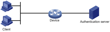
· Client—A user terminal seeking access to the LAN. It must have 802.1X software to authenticate to the network access device.
· Network access device—Authenticates the client to control access to the LAN. In a typical 802.1X environment, the network access device uses an authentication server to perform authentication.
· Authentication server—Provides authentication services for the network access device. The authentication server authenticates 802.1X clients by using the data sent from the network access device, and returns the authentication results for the network access device to make access decisions. The authentication server is typically a RADIUS server. In a small LAN, you can also use the network access device as the authentication server.
Controlled/uncontrolled port and port authorization status
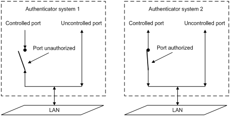
802.1X defines two logical ports for the network access port: controlled port and uncontrolled port. Any packet arriving at the network access port is visible to both logical ports.
· Controlled port—Allows incoming and outgoing traffic to pass through when it is in the authorized state, and denies incoming and outgoing traffic when it is in the unauthorized state, as shown in Figure 2. The controlled port is set in the authorized state if the client has passed authentication, and in the unauthorized state, if the client has failed authentication.
· Uncontrolled port—Always open to receive and transmit EAPOL frames.
Figure 2 Authorization state of a controlled port
In unauthorized state, a controlled port controls traffic in one of the following ways:
· Performs bidirectional traffic control to deny traffic to and from the client.
· Performs unidirectional traffic control to deny traffic from the client.
The H3C devices support only unidirectional traffic control.
802.1X-related protocols
802.1X uses the Extensible Authentication Protocol (EAP) to transport authentication information for the client, the network access device, and the authentication server. EAP is an authentication framework that uses the client/server model. It supports a variety of authentication methods, including MD5-Challenge, EAP-Transport Layer Security (EAP-TLS), and Protected EAP (PEAP).
802.1X defines EAP over LAN (EAPOL) for passing EAP packets between the client and the network access device over a wired or wireless LAN. Between the network access device and the authentication server, 802.1X delivers authentication information in one of the following methods:
· Encapsulates EAP packets in RADIUS by using EAP over RADIUS (EAPOR), as described in "EAP relay."
· Extracts authentication information from the EAP packets and encapsulates the information in standard RADIUS packets, as described in "EAP termination."
Packet formats
EAP packet format
Figure 3 shows the EAP packet format.
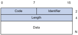
· Code—Type of the EAP packet. Options include Request (1), Response (2), Success (3), or Failure (4).
· Identifier—Used for matching Responses with Requests.
· Length—Length (in bytes) of the EAP packet. The length is the sum of the Code, Identifier, Length, and Data fields.
· Data—Content of the EAP packet. This field appears only in a Request or Response EAP packet. The Data field contains the request type (or the response type) and the type data. Type 1 (Identity) and type 4 (MD5-challenge) are two examples for the type field.
EAPOL packet format
Figure 4 shows the EAPOL packet format.
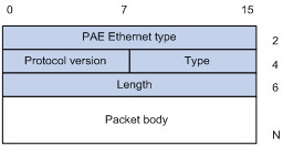
· PAE Ethernet type—Protocol type. It takes the value 0x888E for EAPOL.
· Protocol version—The EAPOL protocol version used by the EAPOL packet sender.
· Type—Type of the EAPOL packet. Table 1 lists the types of EAPOL packets supported by H3C implementation of 802.1X.
Table 1 Types of EAPOL packets
|
Value |
Type |
Description |
|
0x00 |
EAP-Packet |
The client and the network access device uses EAP-Packets to transport authentication information. |
|
0x01 |
EAPOL-Start |
The client sends an EAPOL-Start message to initiate 802.1X authentication to the network access device. |
|
0x02 |
EAPOL-Logoff |
The client sends an EAPOL-Logoff message to tell the network access device that it is logging off. |
· Length—Data length in bytes, or length of the Packet body. If packet type is EAPOL-Start or EAPOL-Logoff, this field is set to 0, and no Packet body field follows.
· Packet body—Content of the packet. When the EAPOL packet type is EAP-Packet, the Packet body field contains an EAP packet.
EAP over RADIUS
RADIUS adds two attributes, EAP-Message and Message-Authenticator, for supporting EAP authentication. For the RADIUS packet format, see "Configuring AAA."
EAP-Message
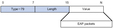
RADIUS encapsulates EAP packets in the EAP-Message attribute, as shown in Figure 5. The Type field takes 79, and the Value field can be up to 253 bytes. If an EAP packet is longer than 253 bytes, RADIUS encapsulates it in multiple EAP-Message attributes.
Figure 5 EAP-Message attribute format
Message-Authenticator
RADIUS includes the Message-Authenticator attribute in all packets that have an EAP-Message attribute to check their integrity. The packet receiver drops the packet if the calculated packet integrity checksum is different from the Message-Authenticator attribute value. The Message-Authenticator prevents EAP authentication packets from being tampered with during EAP authentication.
Figure 6 Message-Authenticator attribute format
![]()
Initiating 802.1X authentication
Both the 802.1X client and the access device can initiate 802.1X authentication.
802.1X client as the initiator
The client sends an EAPOL-Start packet to the access device to initiate 802.1X authentication. The destination MAC address of the packet is the IEEE 802.1X specified multicast address 01-80-C2-00-00-03 or the broadcast MAC address. If any intermediate device between the client and the authentication server does not support the multicast address, use an 802.1X client, the H3C iNode 802.1X client for example, that can send broadcast EAPOL-Start packets.
Access device as the initiator
The access device initiates authentication if a client cannot send EAPOL-Start packets. One example is the 802.1X client available with Windows XP.
The access device supports the following modes:
· Multicast trigger mode—The access device multicasts Identity EAP-Request packets periodically (every 30 seconds by default) to initiate 802.1X authentication.
· Unicast trigger mode—Upon receiving a frame with the source MAC address not in the MAC address table, the access device sends an Identity EAP-Request packet out of the receiving port to the unknown MAC address. It retransmits the packet if no response has been received within a certain time interval.
802.1X authentication procedures
802.1X authentication has two approaches: EAP relay and EAP termination. You choose either mode depending on the support of the RADIUS server for EAP packets and EAP authentication methods.
· EAP relay mode:
EAP relay is defined in IEEE 802.1X. In this mode, the network device uses EAPoR packets to send authentication information to the RADIUS server, as shown in Figure 7.
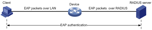
In EAP relay mode, the client must use the same authentication method as the RADIUS server. On the network access device, you only need to use the dot1x authentication-method eap command to enable EAP relay.
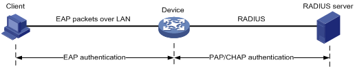
· EAP termination mode:
In EAP termination mode, the network access device terminates the EAP packets received from the client, encapsulates the client authentication information in standard RADIUS packets, and uses PAP or CHAP to authenticate to the RADIUS server, as shown in Figure 8.
A comparison of EAP relay and EAP termination
|
Packet exchange method |
Benefits |
Limitations |
|
EAP relay |
· Supports various EAP authentication methods. · The configuration and processing is simple on the network access device. |
The RADIUS server must support the EAP-Message and Message-Authenticator attributes, and the EAP authentication method used by the client. |
|
EAP termination |
Works with any RADIUS server that supports PAP or CHAP authentication. |
· Supports only MD5-Challenge EAP authentication and the "username + password" EAP authentication initiated by an H3C iNode 802.1X client. · The processing is complex on the network access device. |
EAP relay
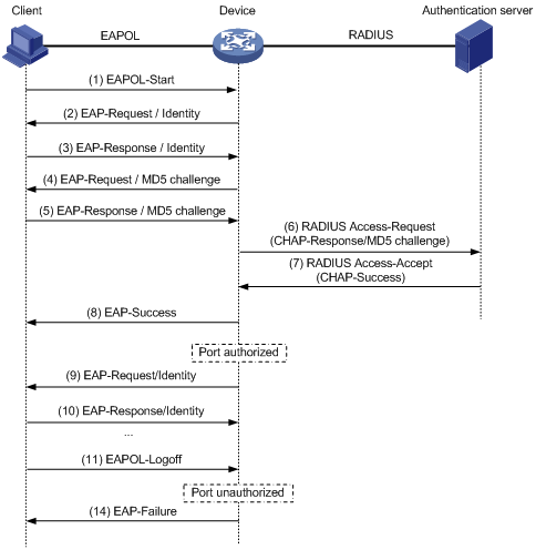
Figure 9 shows the basic 802.1X authentication procedure in EAP relay mode, assuming that EAP-MD5 is used.
Figure 9 802.1X authentication procedure in EAP relay mode
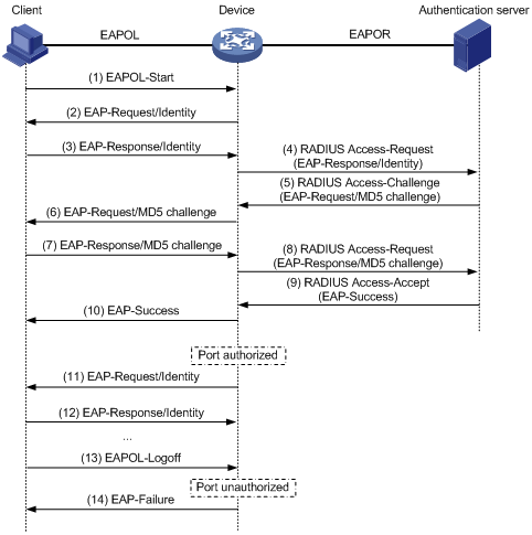
1. When a user launches the 802.1X client software and enters a registered username and password, the 802.1X client software sends an EAPOL-Start packet to the network access device.
2. The network access device responds with an Identity EAP-Request packet to ask for the client username.
3. In response to the Identity EAP-Request packet, the client sends the username in an Identity EAP-Response packet to the network access device.
4. The network access device relays the Identity EAP-Response packet in a RADIUS Access-Request packet to the authentication server.
5. The authentication server uses the identity information in the RADIUS Access-Request to search its user database. If a matching entry is found, the server uses a randomly generated challenge (EAP-Request/MD5 challenge) to encrypt the password in the entry, and sends the challenge in a RADIUS Access-Challenge packet to the network access device.
6. The network access device relays the EAP-Request/MD5 Challenge packet in a RADIUS Access-Request packet to the client.
7. The client uses the received challenge to encrypt the password, and sends the encrypted password in an EAP-Response/MD5 Challenge packet to the network access device.
8. The network access device relays the EAP-Response/MD5 Challenge packet in a RADIUS Access-Request packet to the authentication server.
9. The authentication server compares the received encrypted password with the one it generated at step 5. If the two are identical, the authentication server considers the client valid and sends a RADIUS Access-Accept packet to the network access device.
10. Upon receiving the RADIUS Access-Accept packet, the network access device sends an EAP-Success packet to the client, and sets the controlled port in the authorized state so the client can access the network.
11. After the client comes online, the network access device periodically sends handshake requests to check whether the client is still online. By default, if two consecutive handshake attempts fail, the device logs off the client.
13. The client can also send an EAPOL-Logoff packet to ask the network access device for a logoff.
14. In response to the EAPOL-Logoff packet, the network access device changes the status of the controlled port from authorized to unauthorized and sends an EAP-Failure packet to the client.
EAP termination
Figure 10 shows the basic 802.1X authentication procedure in EAP termination mode, assuming that CHAP authentication is used.
Figure 10 802.1X authentication procedure in EAP termination mode
In EAP termination mode, the network access device rather than the authentication server generates an MD5 challenge for password encryption (see Step 4). The network access device then sends the MD5 challenge together with the username and encrypted password in a standard RADIUS packet to the RADIUS server.
This chapter describes how to configure 802.1X on an H3C device. You can also configure the port security feature to perform 802.1X. Port security combines and extends 802.1X and MAC authentication. It applies to a network, a WLAN, for example, that requires different authentication methods for different users on a port. For more information about port security, see "Configuring port security."
H3C implementation of 802.1X
Access control methods
H3C implements port-based access control as defined in the 802.1X protocol, and extends the protocol to support MAC-based access control.
· Port-based access control—Once an 802.1X user passes authentication on a port, any subsequent user can access the network through the port without authentication. When the authenticated user logs off, all other users are logged off.
· MAC-based access control—Each user is separately authenticated on a port. When a user logs off, no other online users are affected.
Using 802.1X authentication with other features
VLAN assignment
You can configure the authentication server to assign a VLAN for an 802.1X user that has passed authentication. The way that the network access device handles VLANs on an 802.1X-enabled port differs by 802.1X access control mode.
|
Access control |
VLAN manipulation |
|
Port-based |
Assigns the VLAN to the port as the port VLAN (PVID). The authenticated 802.1X user and all subsequent 802.1X users can access the VLAN without authentication. When the user logs off, the previous PVID restores, and all other online users are logged off. |
|
MAC-based |
· If the port is a hybrid port with MAC-based VLAN enabled, the device maps the MAC address of each user to the VLAN assigned by the authentication server. The PVID of the port does not change. When a user logs off, the MAC-to-VLAN mapping for the user is removed. · If the port is an access, trunk, or MAC-based VLAN disabled hybrid port, the device assigns the first authenticated user's VLAN to the port as the PVID. If a different VLAN is assigned to a subsequent user, the user cannot pass the authentication. To avoid the authentication failure of subsequent users, be sure to assign the same VLAN to all 802.1X users on these ports. |
With 802.1X authentication, a hybrid port is always assigned to a VLAN as an untagged member. After the assignment, do not reconfigure the port as a tagged member in the VLAN.
On a periodic online user re-authentication enabled port, if a user has been online before you enable the MAC-based VLAN function, the access device does not create a MAC-to-VLAN mapping for the user unless the user passes re-authentication and the VLAN for the user has changed.
For more information about VLAN configuration and MAC-based VLAN, see Layer 2 Configuration Guide.
ACL assignment
You can specify an ACL for an 802.1X user to control its access to network resources. After the user passes 802.1X authentication, the authentication server, either the local access device or a RADIUS server, assigns the ACL to the port to filter the traffic from this user. In either case, you must configure the ACL on the access device. You can change ACL rules while the user is online.
Configuration prerequisites
· Configure an ISP domain and AAA scheme (local or RADIUS authentication) for 802.1X users.
· If RADIUS authentication is used, create user accounts on the RADIUS server.
· If local authentication is used, create local user accounts on the access device and set the service type to lan-access.
For information about RADIUS client configuration, see "Configuring AAA."
802.1X configuration task list
|
Task |
Remarks |
|
Required |
|
|
Optional |
|
|
Optional |
|
|
Optional |
|
|
Setting the maximum number of concurrent 802.1X users on a port |
Optional |
|
Setting the maximum number of authentication request attempts |
Optional |
|
Optional |
|
|
Optional |
|
|
Optional |
|
|
Optional |
|
|
Optional |
|
|
Optional |
|
|
Enabling the periodic online user re-authentication function |
Optional |
|
Optional |
Enabling 802.1X
Follow these guidelines when you enable 802.1X:
· Do not enable 802.1X on a port that is in a link aggregation group.
· On an 802.1X and MAC authentication enabled port, the EAP packet from an unknown MAC address immediately triggers 802.1X authentication, and any other type of packet from an unknown MAC address triggers MAC authentication 30 seconds after its arrival.
To enable 802.1X:
|
Step |
Command |
Remarks |
|
1. Enter system view. |
system-view |
N/A |
|
2. Enable 802.1X globally. |
dot1x |
By default, 802.1X is disabled globally. |
|
3. Enable 802.1X on a port in system view or Ethernet interface view. |
·
In system view: · In Ethernet interface view: a. interface interface-type interface-number b. dot1x |
By default, 802.1X is disabled on a port. |
Enabling EAP relay or EAP termination
When configuring EAP relay or EAP termination, consider the following factors:
· The support of the RADIUS server for EAP packets
· The authentication methods supported by the 802.1X client and the RADIUS server
If the client is using only MD5-Challenge EAP authentication or the "username + password" EAP authentication initiated by an H3C iNode 802.1X client, you can use both EAP termination and EAP relay. To use EAP-TL, PEAP, or any other EAP authentication methods, you must use EAP relay. When you make your decision, see "A comparison of EAP relay and EAP termination" for help.
For more information about EAP relay and EAP termination, see "802.1X authentication procedures."
To configure EAP relay or EAP termination:
|
Step |
Command |
Remarks |
|
1. Enter system view. |
system-view |
N/A |
|
2. Configure EAP relay or EAP termination. |
dot1x authentication-method { chap | eap | pap } |
By default, the network access device performs EAP termination and uses CHAP to communicate with the RADIUS server. Specify the eap keyword to enable EAP relay. Specify the chap or pap keyword to enable CHAP-enabled or PAP-enabled EAP termination. |
|
|
NOTE: If EAP relay mode is used, the user-name-format command configured in RADIUS scheme view does not take effect. The access device sends the authentication data from the client to the server without any modification. |
Setting the port authorization state
The port authorization state determines whether the client is granted access to the network. You can control the authorization state of a port by using the dot1x port-control command and the following keywords:
· authorized-force—Places the port in the authorized state, enabling users on the port to access the network without authentication.
· unauthorized-force—Places the port in the unauthorized state, denying any access requests from users on the port.
· auto—Places the port initially in the unauthorized state to allow only EAPOL packets to pass, and after a user passes authentication, sets the port in the authorized state to allow access to the network. You can use this option in most scenarios.
You can set authorization state for one port in interface view, or for multiple ports in system view. If different authorization state is set for a port in system view and interface view, the one set later takes effect.
To set the authorization state of a port:
|
Step |
Command |
Remarks |
|
1. Enter system view. |
system-view |
N/A |
|
2. Set the port authorization state in system view or interface view. |
·
In
system view: · In Ethernet interface or WLAN-BSS interface view: a. interface interface-type interface-number b. dot1x port-control { authorized-force | auto | unauthorized-force } |
By default, auto applies. |
Specifying an access control method
You can specify an access control method for one port in interface view, or for multiple ports in system view. If different access control methods are specified for a port in system view and interface view, the one specified later takes effect.
To specify the access control method:
|
Step |
Command |
Remarks |
|
1. Enter system view. |
system-view |
N/A |
|
2. Specify an access control method in system view or interface view. |
·
In system view: · In Ethernet interface or WLAN-BSS interface view: a. interface interface-type interface-number b. dot1x port-method { macbased | portbased } |
By default, MAC-based access control applies. |
Setting the maximum number of concurrent 802.1X users on a port
You can set the maximum number of concurrent 802.1X users for ports individually in interface view or in bulk in system view. If different settings are configured for a port in both views, the setting configured later takes effect.
To set the maximum number of concurrent 802.1X users on a port:
|
Step |
Command |
Remarks |
|
1. Enter system view. |
system-view |
N/A |
|
2. Set the maximum number of concurrent 802.1X users on a port in system view or interface view. |
·
In system view: · In Ethernet interface or WLAN-BSS interface view: a. interface interface-type interface-number b. dot1x max-user user-number |
The default setting is 128. |
Setting the maximum number of authentication request attempts
The network access device retransmits an authentication request if it receives no response to the request it has sent to the client within a period of time (specified by using the dot1x timer tx-period tx-period-value command or the dot1x timer supp-timeout supp-timeout-value command). The network access device stops retransmitting the request, if it has made the maximum number of request transmission attempts but still received no response.
To set the maximum number of authentication request attempts:
|
Step |
Command |
Remarks |
|
1. Enter system view. |
system-view |
N/A |
|
2. Set the maximum number of attempts for sending an authentication request. |
dot1x retry max-retry-value |
The default setting is 2. |
Setting the 802.1X authentication timeout timers
The network device uses the following 802.1X authentication timeout timers:
· Client timeout timer—Starts when the access device sends an EAP-Request/MD5 Challenge packet to a client. If no response is received when this timer expires, the access device retransmits the request to the client.
· Server timeout timer—Starts when the access device sends a RADIUS Access-Request packet to the authentication server. If no response is received when this timer expires, the access device retransmits the request to the server.
You can set the client timeout timer to a high value in a low-performance network, and adjust the server timeout timer to adapt to the performance of different authentication servers. In most cases, the default settings are sufficient.
To set the 802.1X authentication timeout timers:
|
Step |
Command |
Remarks |
|
1. Enter system view. |
system-view |
N/A |
|
2. Set the client timeout timer. |
dot1x timer supp-timeout supp-timeout-value |
The default is 30 seconds. |
|
3. Set the server timeout timer. |
dot1x timer server-timeout server-timeout-value |
The default is 100 seconds. |
Configuring the online user handshake function
The online user handshake function checks the connectivity status of online 802.1X users. The network access device sends handshake messages to online users at the interval specified by the dot1x timer handshake-period command. If no response is received from an online user after the maximum number of handshake attempts (set by the dot1x retry command) has been made, the network access device sets the user in the offline state.
If iNode clients are deployed, you can also enable the online handshake security function to check for 802.1X users that use illegal client software to bypass security inspection such as proxy detection and dual network interface cards (NICs) detection. This function checks the authentication information in client handshake messages. If a user fails the authentication, the network access device logs the user off.
Configuration guidelines
Follow these guidelines when you configure the online user handshake function:
· To use the online handshake security function, make sure the online user handshake function is enabled. H3C recommends that you use the iNode client software and iMC server to ensure the normal operation of the online user handshake security function.
· If the network has 802.1X clients that cannot exchange handshake packets with the network access device, disable the online user handshake function to prevent their connections from being inappropriately torn down.
· You must disable proxy detection before disabling the online user handshake function.
Configuration procedure
To configure the online user handshake function:
|
Step |
Command |
Remarks |
|
1. Enter system view. |
system-view |
N/A |
|
2. Set the handshake timer. |
dot1x timer handshake-period handshake-period-value |
Optional. The default is 15 seconds. |
|
3. Enter Ethernet interface or WLAN-BSS interface view. |
interface interface-type interface-number |
N/A |
|
4. Enable the online handshake function. |
dot1x handshake |
Optional. By default, the function is enabled. |
|
5. Enable the online handshake security function. |
dot1x handshake secure |
Optional. By default, the function is disabled. |
Enabling the proxy detection function
The proxy detection function prevents users from using an authenticated 802.1X client as a network access proxy to bypass monitoring and accounting. When a user is detected accessing the network through a proxy, the network access device can send traps to the network management system or log the user off by sending an offline message.
Before you enable the proxy detection function, complete the following tasks:
· Enable the online user handshake function (see "Configuring the online user handshake function").
· Deploy H3C iNode client software in your network.
To configure the proxy detection function:
|
Step |
Command |
Remarks |
|
1. Enter system view. |
system-view |
N/A |
|
2. Enable the proxy detection function globally. |
dot1x supp-proxy-check { logoff | trap } |
By default, the function is disabled. |
|
3. Enable the proxy detection function on one or more ports in system view or interface view. |
·
In system view: · In Ethernet interface or WLAN-BSS interface view: a. interface interface-type interface-number b. dot1x supp-proxy-check { logoff | trap } |
By default, the function is disabled. |
|
|
NOTE: If you configure the proxy detection function for a port in both system view and interface view, the setting configured the last takes effect. |
Configuring the authentication trigger function
The authentication trigger function enables the network access device to initiate 802.1X authentication when 802.1X clients cannot initiate authentication.
This function provides the following types of authentication trigger:
· Multicast trigger—Periodically multicasts Identity EAP-Request packets out of a port to detect 802.1X clients and trigger authentication.
· Unicast trigger—Enables the network device to initiate 802.1X authentication when it receives a data frame from an unknown source MAC address. The device sends a unicast Identity EAP/Request packet to the unknown source MAC address, and retransmits the packet if it has received no response within a period of time. This process continues until the maximum number of request attempts set with the dot1x retry command (see "Setting the maximum number of authentication request attempts") is reached.
The identity request timeout timer sets both the identity request interval for the multicast trigger and the identity request timeout interval for the unicast trigger.
Configuration guidelines
Follow these guidelines when you configure the authentication trigger function:
· Enable the multicast trigger on a port when the clients attached to the port cannot send EAPOL-Start packets to initiate 802.1X authentication.
· Disable the multicast trigger in a wireless LAN. Wireless clients and the wireless module of the network access device can both initiate 802.1X authentication.
· Enable the unicast trigger on a port if only a few 802.1X clients are attached to the port and these clients cannot initiate authentication.
· To avoid duplicate authentication packets, do not enable both triggers on a port.
Configuration procedure
To configure the authentication trigger function on a port:
|
Step |
Command |
Remarks |
|
1. Enter system view. |
system-view |
N/A |
|
2. Set the username request timeout timer. |
dot1x timer tx-period tx-period-value |
Optional. The default setting is 30 seconds. |
|
3. Enable an authentication trigger. |
· In Ethernet interface or WLAN-BSS interface view: a. interface interface-type interface-number b. dot1x multicast-trigger · In Ethernet interface view: a. interface interface-type interface-number b. dot1x unicast-trigger |
Required if you want to enable the unicast trigger. By default, the multicast trigger is enabled, and the unicast trigger is disabled. |
Specifying a mandatory authentication domain on a port
You can place all 802.1X users in a mandatory authentication domain for authentication, authorization, and accounting on a port. No user can use an account in any other domain to access the network through the port. The implementation of a mandatory authentication domain enhances the flexibility of 802.1X access control deployment.
To specify a mandatory authentication domain for a port:
|
Step |
Command |
Remarks |
|
1. Enter system view. |
system-view |
N/A |
|
2. Enter Ethernet interface or WLAN-BSS interface view. |
interface interface-type interface-number |
N/A |
|
3. Specify a mandatory 802.1X authentication domain on the port. |
dot1x mandatory-domain domain-name |
By default, no mandatory 802.1X authentication domain is specified. |
Configuring the quiet timer
The quiet timer enables the network access device to wait a period of time before it can process any authentication request from a client that has failed an 802.1X authentication.
You can set the quiet timer to a high value in a vulnerable network or a low value for quicker authentication response.
To configure the quiet timer:
|
Step |
Command |
Remarks |
|
1. Enter system view. |
system-view |
N/A |
|
2. Enable the quiet timer. |
dot1x quiet-period |
By default, the timer is disabled. |
|
3. Set the quiet timer. |
dot1x timer quiet-period quiet-period-value |
Optional. The default setting is 60 seconds. |
Enabling the periodic online user re-authentication function
Periodic online user re-authentication tracks the connection status of online users and updates the authorization attributes assigned by the server, such as the ACL and VLAN. The re-authentication interval is user configurable.
To enable the periodic online user re-authentication function:
|
Step |
Command |
Remarks |
|
1. Enter system view. |
system-view |
N/A |
|
2. Set the periodic re-authentication timer. |
dot1x timer reauth-period reauth-period-value |
Optional. The default setting is 3600 seconds. |
|
3. Enter Ethernet interface or WLAN-BSS interface view. |
interface interface-type interface-number |
N/A |
|
4. Enable periodic online user re-authentication. |
dot1x re-authenticate |
By default, the function is disabled. |
The periodic online user re-authentication timer can also be set by the authentication server in the session-timeout attribute. The server-assigned timer overrides the timer setting on the access device, and enables periodic online user re-authentication, even if the function is not configured. Support for the server assignment of re-authentication timer and the re-authentication timer configuration on the server vary with servers.
The VLAN assignment status must be consistent before and after re-authentication. If the authentication server has assigned a VLAN before re-authentication, it must also assign a VLAN at re-authentication. If the authentication server has assigned no VLAN before re-authentication, it must not assign one at re-authentication. Violation of either rule can cause the user to be logged off. The VLANs assigned to an online user before and after re-authentication can be the same or different.
Specifying supported domain name delimiters
By default, the access device supports the at sign (@) as the delimiter. You can also configure the access device to accommodate 802.1X users that use other domain name delimiters.
The configurable delimiters include the at sign (@), back slash (\), and forward slash (/).
If an 802.1X username string contains multiple configured delimiters, the leftmost delimiter is the domain name delimiter. For example, if you configure @, /, and \ as delimiters, the domain name delimiter for the username string 123/22\@abc is the forward slash (/).
If a username string contains none of the delimiters, the access device authenticates the user in the mandatory or default ISP domain. The access selects a domain delimiter from the delimiter set in this order: @, /, and \.
To specify a set of domain name delimiters:
|
Step |
Command |
Remarks |
|
1. Enter system view. |
system-view |
N/A |
|
2. Specify a set of domain name delimiters for 802.1X users. |
dot1x domain-delimiter string |
By default, only the at sign (@) delimiter is supported. |
|
|
NOTE: If you configure the access device to include the domain name in the username sent to the RADIUS server, make sure the domain delimiter in the username can be recognized by the RADIUS server. For username format configuration, see the user-name-format command in Security Command Reference. |
Displaying and maintaining 802.1X
|
Task |
Command |
Remarks |
|
Display 802.1X session information, statistics, or configuration information of specified or all ports. |
display dot1x [ sessions | statistics ] [ interface interface-list ] [ | { begin | exclude | include } regular-expression ] |
Available in any view. |
|
Clear 802.1X statistics. |
reset dot1x statistics [ interface interface-list ] |
Available in user view. |
802.1X with IAS configuration example
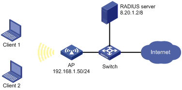
Network requirements
As shown in Figure 11, configure the access point (AP) to use the RADIUS server to perform authentication and accounting for users logging into the AP.
· The RADIUS server at 8.20.1.2/8, is connected with the AP through the switch.
· On the AP, configure the shared key for packet exchange with the RADIUS server as h3c, and configure the system to remove the domain name of a username before sending it to the RADIUS server.
· On the RADIUS server, configure the shared key for packet exchange with the AP as h3c.
· Configure the AP to send real-time accounting packets to the RADIUS server every three minutes.
· Configure the AP to drop the buffered stop-accounting packets getting no responses.
· Enable the accounting-on function on the AP, so that the AP sends accounting-on packets to the RADIUS server whenever it reboots. This function allows the server to log out the users that have logged in through the AP before reboot, solving the problem that users online before the reboot cannot re-log in after the reboot.
Configuration procedure
1. Configure the AP.
# Enable port security, and specify the 802.1X authentication method as EAP.
<AP> system-view
[AP] port-security enable
[AP] dot1x authentication-method eap
# Configure RADIUS scheme ias.
[AP] radius scheme ias
[AP-radius-ias] server-type extended
[AP-radius-ias] primary authentication 8.20.1.2
[AP-radius-ias] primary accounting 8.20.1.2
[AP-radius-ias] key authentication h3c
[AP-radius-ias] key accounting h3c
[AP-radius-ias] user-name-format without-domain
[AP-radius-ias] timer realtime-accounting 3
[AP-radius-ias] undo stop-accounting-buffer enable
[AP-radius-ias] accounting-on enable
# Configure the 192.168.1.50 as the source IP address for RADIUS packets.
[AP-radius-ias] nas-ip 192.168.1.50
[AP-radius-ias] quit
# Configure the authentication, authorization, and accounting methods to be used by the authentication domain.
[AP] domain ias
[AP-isp-ias] authentication lan-access radius-scheme ias
[AP-isp-ias] authorization lan-access radius-scheme ias
[AP-isp-ias] accounting lan-access radius-scheme ias
[AP-isp-ias] quit
# Configure authentication domain ias as the default domain of the system.
[AP] domain default enable ias
# Configure port WLAN-BSS 2, specify the 802.1X authentication method on the interface as EAP (the port security mode is userLoginSecureExt). Disable the online user handshake function, and the 802.1X multicast trigger function.
[AP] interface wlan-bss 2
[AP-WLAN-BSS2] port-security port-mode userlogin-secure-ext
[AP-WLAN-BSS2] port-security tx-key-type 11key
[AP-WLAN-BSS2] undo dot1x handshake
[AP-WLAN-BSS2] undo dot1x multicast-trigger
[AP-WLAN-BSS2] quit
# Configure a WLAN service template.
[AP] wlan service-template 2 crypto
[AP-wlan-st-2] ssid h3c-dot1x
[AP-wlan-st-2] authentication-method open-system
[AP-wlan-st-2] cipher-suite ccmp
[AP-wlan-st-2] security-ie rsn
[AP-wlan-st-2] service-template enable
[AP-wlan-st-2] quit
# On the radio port, bind the wireless port and the service template.
[AP] interface wlan-radio 1/0/1
[AP-WLAN-Radio1/0/1] service-template 2 interface wlan-bss 2
[AP-WLAN-Radio1/0/1] quit
# Configure the VLAN interface.
[AP] interface vlan-interface 1
[AP-Vlan-interface1] ip address 192.168.1.50 255.255.255.0
[AP-Vlan-interface1] quit
# Configure a default route.
[AP] ip route-static 0.0.0.0 0.0.0.0 192.168.1.1
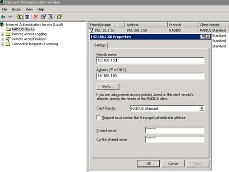
2. Configure the RADIUS server.
# Configure the RADIUS client.
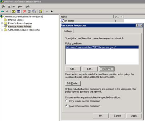
# Configure the remote access policy.
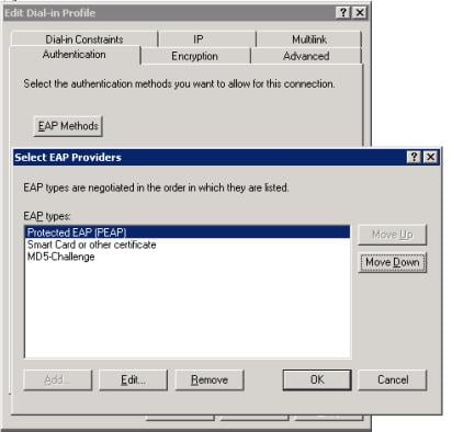
# Edit the dial-in configuration file.
Verifying the configuration
On the host that runs Windows XP, configure the wireless network interface card as follows:
· Add a network with the SSID h3c-dot1x.
· Set the authentication type to RSN.
· Set the data encryption method to CCMP.
· Set the EAP type to Protected EAP (PEAP).
Use the client to trigger authentication. After typing the correct username and password, the client can pass authentication. Execute the display connection command on the AP to check the user connection information.
For RADIUS server related configurations such as the certificates needed for certificate authentication and users in the AD, see the Windows help files.