- Table of Contents
-
- 01-Fundamentals Configuration Guide
- 00-Preface
- 01-CLI configuration
- 02-RBAC configuration
- 03-Login management configuration
- 04-FTP and TFTP configuration
- 05-File system management configuration
- 06-Configuration file management configuration
- 07-Software upgrade configuration
- 08-GIR configuration
- 09-Automatic configuration
- 10-Target configuration management configuration
- 11-Device management configuration
- 12-Tcl configuration
- 13-Python configuration
- 14-Management with BootWare
- Related Documents
-
| Title | Size | Download |
|---|---|---|
| 11-Device management configuration | 425.88 KB |
Device management restrictions and guidelines
Device management tasks at a glance
Restrictions and guidelines for configuring the system time
System time configuration tasks at a glance
Setting the system time at the CLI
Obtaining the UTC time through NTP or PTP
Setting the daylight saving time
Enabling displaying the copyright statement
Disabling password recovery capability
Setting the operating mode for an interface card
Setting the operating mode for a slot
Setting the port status detection timer
Monitoring kernel memory fragments
Configuring resource monitoring
Setting the temperature alarm thresholds
Specifying the energy saving mode
Configuring energy saving for excess power modules
Configuring auto laser shutdown
Specifying the restart mode for the laser of a transceiver module
Configuring error logging for software and hardware forwarding entries
Configuring consistency error logging for software and hardware forwarding entries
Configuring parity error and ECC error logging for entries on forwarding chips
Configuring uncorrectable parity error and ECC error logging for entries on forwarding chips
Configuring overtemperature auto shutdown
Setting the card power-on control mode
Enabling hardware detection reporting
Configuring hardware failure detection and protection
About hardware failure detection and protection
Specifying the actions to be taken for hardware failures
Enabling hardware failure protection for interfaces
Enabling hardware failure protection for aggregation groups
Enabling data forwarding path failure detection
Setting the fan operating mode
Adjusting the percentage of the current fan speed to the maximum fan speed
Verifying and diagnosing transceiver modules
Diagnosing transceiver modules
Specifying an ITU channel number for a transceiver module
Enabling a lane on a transceiver module
Configuring CDR on transmit or receive lanes
Setting the power mode for a transceiver module
Displaying transceiver module information
Restrictions and guidelines for task scheduling
Enabling removal interrupt signal reporting
Restrictions and guidelines for device reboot
Rebooting devices immediately at the CLI
Restoring the factory-default configuration
Display and maintenance commands for device management configuration
Managing the device
About device management
This chapter describes how to configure basic device parameters and manage the device. You can perform the configuration tasks in this chapter in any order.
Device management restrictions and guidelines
After being powered on, a card takes some time to start up and complete configuration and data restoration and synchronization. Before configuring the card, use the display device and display system stable state commands to verify that the card is in Normal and Stable states. Failing to follow this rule might cause configuration failures and even device exceptions.
Device management tasks at a glance
All device management tasks are optional. You can perform any of the tasks in any order.
· Configuring basic parameters
¡ Enabling displaying the copyright statement
· Configuring security parameters
¡ Disabling password recovery capability
· Adjusting device capacities
¡ Setting the operating mode for an interface card
¡ Setting the port status detection timer
· Monitoring the device
¡ Configuring resource monitoring
¡ Setting the temperature alarm thresholds
¡ Configuring error logging for software and hardware forwarding entries
¡ Setting the card power-on control mode
¡ Enabling hardware detection reporting
¡ Configuring hardware failure detection and protection
¡ Enabling data forwarding path failure detection
· Managing resources
¡ Setting the fan operating mode
¡ Adjusting the percentage of the current fan speed to the maximum fan speed
¡ Verifying and diagnosing transceiver modules
¡ Specifying an ITU channel number for a transceiver module
¡ Managing transceiver modules
· Maintaining the device
¡ Enabling removal interrupt signal reporting
¡ Restoring the factory-default configuration
Configuring the device name
About this task
A device name (also called hostname) identifies a device in a network and is used in CLI view prompts. For example, if the device name is Sysname, the user view prompt is <Sysname>.
Procedure
1. Enter system view.
system-view
sysname sysname
By default, the device name is H3C.
Configuring the system time
About the system time
Correct system time is essential to network management and communication. Configure the system time correctly before you run the device on the network.
The device can use one of the following methods to obtain the system time:
· Uses the locally set system time, and then uses the clock signals generated by its built-in crystal oscillator to maintain the system time.
· Periodically obtains the UTC time from an NTP or PTP source and uses the UTC time, time zone, and daylight saving time to calculate the system time. For more information about NTP and PTP, see Network Management and Monitoring Configuration Guide.
The system time calculated by using the UTC time from a time source is more precise.
Restrictions and guidelines for configuring the system time
After you configure the clock protocol none command, the clock datetime command determines the system time, whether or not the time zone or daylight saving time has been configured.
If you configure or change the time zone or daylight saving time after the device obtains the system time, the device recalculates the system time. To view the system time, use the display clock command.
System time configuration tasks at a glance
To configure the system time, perform the following tasks:
1. Configuring the system time
Choose one of the following tasks:
¡ Setting the system time at the CLI
¡ Obtaining the UTC time through NTP or PTP
2. (Optional.) Setting the time zone
Make sure each network device uses the time zone of the place where the device resides.
3. (Optional.) Setting the daylight saving time
Make sure each network device uses the daylight saving time parameters of the place where the device resides.
Setting the system time at the CLI
1. Enter system view.
system-view
2. Configure the device to use the local system time.
clock protocol none
By default, the device uses NTP to obtain the UTC time.
If you execute this command multiple times, the most recent configuration takes effect.
3. Return to user view.
quit
4. Set the local system time.
clock datetime time date
By default, the factory-default system time is used.
|
|
CAUTION: This command changes the system time, which affects the execution of system time-related features (for example, scheduled tasks) and collaborative operations of the device with other devices (for example, log reporting and statistics collection). Before executing this command, make sure you fully understand its impact on your live network. |
Obtaining the UTC time through NTP or PTP
1. Enter system view.
system-view
2. Specify the system time source.
clock protocol { ntp | ptp } mdc mdc-id
By default, the device uses NTP to obtain the UTC time.
If you execute this command multiple times, the most recent configuration takes effect.
3. Configure time protocol parameters.
For more information about NTP and PTP configuration, see Network Management and Monitoring Configuration Guide.
Setting the time zone
1. Enter system view.
system-view
2. Set the time zone.
clock timezone zone-name { add | minus } zone-offset
By default, the system uses the UTC time zone.
Setting the daylight saving time
1. Enter system view.
system-view
2. Set the daylight saving time.
clock summer-time name start-time start-date end-time end-date add-time
By default, the daylight saving time is not set.
Enabling displaying the copyright statement
About this task
This feature enables the device to display the copyright statement in the following situations:
· When a Telnet or SSH user logs in.
· When a console user quits user view. This is because the device automatically tries to restart the user session.
If you disable displaying the copyright statement, the device does not display the copyright statement in any situations.
Procedure
1. Enter system view.
system-view
2. Enable displaying the copyright statement.
copyright-info enable
By default, displaying the copyright statement is enabled.
Configuring banners
About this task
Banners are messages that the system displays when a user logs in.
The system supports the following banners:
· Legal banner—Appears after the copyright statement.
· Message of the Day (MOTD) banner—Appears after the legal banner and before the login banner.
· Login banner—Appears only when password or scheme authentication is configured.
· Shell banner—Appears before the user enters user view.
The system displays the banners in the following order: legal banner, MOTD banner, login banner, and shell banner.
Banner input methods
You can configure a banner by using one of the following methods:
· Input the entire command line in a single line.
The banner cannot contain carriage returns. The entire command line, including the command keywords, the banner, and the delimiters, can have a maximum of 511 characters. The delimiters for the banner can be any printable character but must be the same. You cannot press Enter before you input the end delimiter.
For example, you can configure the shell banner "Have a nice day." as follows:
<Sysname> system-view
[Sysname] header shell %Have a nice day.%
· Input the command line in multiple lines.
The banner can contain carriage returns. A carriage return is counted as two characters.
To input a banner configuration command line in multiple lines, use one of the following methods:
¡ Press Enter after the final command keyword, type the banner, and end the final line with the delimiter character %. The banner plus the delimiter can have a maximum of 1999 characters.
For example, you can configure the banner "Have a nice day." as follows:
<Sysname> system-view
[Sysname] header shell
Please input banner content, and quit with the character '%'.
Have a nice day.%
¡ After you type the final command keyword, type any printable character as the start delimiter for the banner and press Enter. Then, type the banner and end the final line with the same delimiter. The banner plus the end delimiter can have a maximum of 1999 characters.
For example, you can configure the banner "Have a nice day." as follows:
<Sysname> system-view
[Sysname] header shell A
Please input banner content, and quit with the character 'A'.
Have a nice day.A
¡ After you type the final command keyword, type the start delimiter and part of the banner. Make sure the final character of the final string is different from the start delimiter. Then, press Enter, type the rest of the banner, and end the final line with the same delimiter. The banner plus the start and end delimiters can have a maximum of 2002 characters.
For example, you can configure the banner "Have a nice day." as follows:
<Sysname> system-view
[Sysname] header shell AHave a nice day.
Please input banner content, and quit with the character 'A'.
A
Procedure
1. Enter system view.
system-view
2. Configure one or more banners:
¡ Configure the legal banner.
header legal text
¡ Configure the MOTD banner.
header motd text
¡ Configure the login banner.
header login text
¡ Configure the shell banner.
header shell text
Disabling password recovery capability
About this task
Password recovery capability controls console user access to the device configuration and SDRAM from BootWare menus. For more information about BootWare menus, see the release notes.
If password recovery capability is enabled, a console user can access the device configuration without authentication to configure a new password.
If password recovery capability is disabled, console users must restore the factory-default configuration before they can configure new passwords. Restoring the factory-default configuration deletes the next-startup configuration files.
To enhance system security, disable password recovery capability.
Restrictions and guidelines
To access the device configuration without authentication, you must connect to the active MPU and access the BootWare menu while the MPU is starting up.
Procedure
1. Enter system view.
system-view
2. Disable password recovery capability.
undo password-recovery enable
By default, password recovery capability is enabled.
Setting the operating mode for an interface card
About this task
Use this feature to set the operating mode for an interface card.
Restrictions and guidelines
This feature is available only for the MIC-SP4L-M and MIC-SEC-M interface cards.
The MIC-SP4L-M interface card supports the following modes:
· oc-3-pos: Specifies the oc-3-pos mode. All interfaces on the interface card act as POS interfaces.
· oc-12-pos: Specifies the oc-12-pos mode. All interfaces on the interface card act as POS interfaces.
The MIC-SEC-M interface card supports the following modes:
· ipsec-md5-aes: Specifies the encryption mode of the IPsec encryption interface card as IPsec-MD5-AES, which supports MD5 authentication algorithm and AES-CBC-256 encryption algorithm.
· ipsec-sm3-sm4: Specifies the encryption mode of the IPsec encryption interface card as IPsec-SM3-SM4, which supports SM3 authentication algorithm and SM4 encryption algorithm.
If you change the operating mode for an interface card, the card reboots to operate in the new operating mode.
If the card is damaged and replaced with a new one of the same model, the following rules apply:
· For an MIC-SP4L-M interface card, the operating mode configured currently on the device takes effect on the new card.
· For an MIC-SEC-M interface card, the default operating mode takes effect. If the default operating mode does not match the operating mode for the original card before replacement, you must reconfigure an operating mode.
Procdure
1. Enter system view.
system-view
2. Set the operating mode for an interface card.
line-card-mode slot slot-number mode-name
By default, the MIC-SP4L-M interface card operates in the oc-3-pos mode and the MIC-SEC-M interface card operates in ipsec-sm3-sm4 mode.
Setting the operating mode for a slot
Restrictions and guidelines
This feature is supported only on the MIC-CQ1LF-M and MIC-XP10L-M interface cards.
For information about switching between the standard Ethernet mode and the flexible Ethernet mode, see FlexE interface configuration in Interface Configuration Guide.
If a card installed in the specified slot does not support this feature, the feature setting will be deleted or fails to be configured.
Procedure
1. Enter system view.
system-view
2. Set the operating mode for a slot.
subslot-working-mode slot slot-number { ethernet-flexe | detnet | ethernet-flexe-otn }
Setting the port status detection timer
About this task
The device starts a port status detection timer when a port is shut down by a protocol. If the port has been in down state before the timer expires, the device will set the port status to the port's physical status.
Procedure
1. Enter system view.
system-view
2. Set the port status detection timer.
shutdown-interval time
The default setting is 30 seconds.
Monitoring CPU usage
About this task
To monitor CPU usage, the device performs the following operations:
· Samples CPU usage at 1-minute intervals, and compares the samples with CPU usage thresholds to identify the CPU usage status and send alarms or notifications accordingly.
· Samples and saves CPU usage at a configurable interval if CPU usage tracking is enabled. You can use the display cpu-usage history command to display the historical CPU usage statistics in a coordinate system.
The device supports the following CPU usage thresholds:
· Minor threshold—If the CPU usage increases above the minor threshold but is less than or equal to the severe threshold, the CPU usage enters minor alarm state. The device sends minor alarms periodically until the CPU usage increases above the severe threshold or the minor alarm is removed.
· Severe threshold—If the CPU usage increases above the severe threshold, the CPU usage enters severe alarm state. The device sends severe alarms periodically until the severe alarm is removed.
· Recovery threshold—If the CPU usage decreases below the recovery threshold, the CPU usage enters recovered state. The device sends a recovery notification.
CPU usage alarms and notifications are sent to NETCONF, SNMP, and the information center to be encapsulated as NETCONF events, SNMP traps and informs, and log messages. For more information, see NETCONF, SNMP, and information center in Network Management and Monitoring Configuration Guide.
Figure 1 CPU alarms and alarm-removed notifications

Procedure
1. Enter system view.
system-view
2. Set the CPU usage thresholds.
monitor cpu-usage threshold cpu-threshold [ minor-threshold minor-threshold recovery-threshold recovery-threshold ] [ slot slot-number [ cpu cpu-number ] ]
The default settings are as follows:
¡ Severe CPU usage alarm threshold—99%.
¡ Minor CPU usage alarm threshold—79%.
¡ CPU usage recovery threshold—69%.
|
|
CAUTION: If you set the severe CPU usage threshold to a too low value, the device will reach the threshold easily. Normal service processing will be affected. |
3. Set the CPU usage alarm resending intervals.
monitor resend cpu-usage { minor-interval minor-interval | severe-interval severe-interval } * [ slot slot-number [ cpu cpu-number ] ]
By default, the minor CPU usage alarm resending interval and severe CPU usage alarm resending interval are 300 seconds and 60 seconds, respectively.
4. Set the sampling interval for CPU usage tracking.
monitor cpu-usage interval interval [ slot slot-number [ cpu cpu-number ] ]
By default, the sampling interval for CPU usage tracking is 1 minute.
5. Enable CPU usage tracking.
monitor cpu-usage enable [ slot slot-number [ cpu cpu-number ] ]
By default, CPU usage tracking is enabled.
Monitoring CPU core usage
About this task
The device samples CPU core usage at 5-second intervals and calculates the average value during each CPU core usage statistics interval. If the value during an interval is greater than a CPU core usage threshold, the device sends an alarm notification.
CPU core usage alarm notifications are sent to NETCONF, SNMP, and the information center to be encapsulated as NETCONF events, SNMP traps and informs, and log messages. For more information about NETCONF, SNMP, and information center, see Network Management and Monitoring Configuration Guide.
Restrictions and guidelines
As a best practice, set the CPU core usage statistics interval to a multiple of 5. If you do not do so, the effective statistics interval is the biggest multiple of 5 that is smaller than the setting. For example, if you set this statistics interval to 12 seconds, the effective statistics interval is 10 seconds.
Procedure
1. Enter system view.
system-view
2. Set CPU core alarm resending intervals.
monitor resend cpu-usage core-interval { minor-interval minor-interval | severe-interval severe-interval } * [ slot slot-number [ cpu cpu-number ] ]
By default, the resending interval is 60 seconds for severe CPU core usage alarms and 300 seconds for minor CPU core usage alarms.
Monitoring memory
Monitoring memory usage
About this task
The device samples memory usage at 1-minute intervals, and compares the sampled value with the memory usage threshold. If the sampled value exceeds the threshold, the device sends an alarm notification.
Memory usage alarm notifications are sent to NETCONF, SNMP, and the information center to be encapsulated as NETCONF events, SNMP traps and informs, and log messages. For more information about NETCONF, SNMP, and information center, see Network Management and Monitoring Configuration Guide.
Procedure
1. Enter system view.
system-view
2. Set the memory usage threshold.
memory-threshold [ slot slot-number [ cpu cpu-number ] ] usage memory-threshold
By default, the memory usage threshold is 100%.
3. Set the memory usage alarm resending interval.
memory-threshold [ slot slot-number [ cpu cpu-number ] ] usage resend-interval interval-value
By default, the memory usage alarm resending interval is 300 seconds.
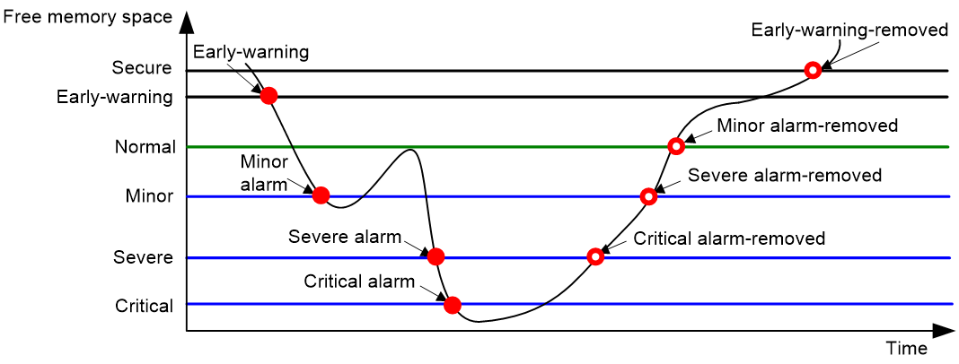
Monitoring free memory
About this task
The device monitors the amount of free memory space in real time. If the amount of free memory space reaches a free-memory threshold, the system generates an alarm notification and sends it to affected service modules or processes. If the amount of free memory space drops below a free-memory threshold, the system generates an alarm-removed notification and sends it to affected service modules or processes
As shown in Table 1 and Table 1Figure 2, the system supports the following free-memory thresholds listed in ascending severity level:
· Sufficient-memory threshold.
· Early-warning threshold. An early warning alarm warns you of an approaching insufficient-memory condition.
· Normal state threshold.
· Minor alarm threshold.
· Severe alarm threshold.
· Critical alarm threshold.
Table 1 Memory alarm notifications and memory alarm-removed notifications
|
Notification |
Triggering condition |
Remarks |
|
Early-warning notification |
The amount of free memory space decreases below the early-warning threshold. |
After generating and sending an early-warning notification, the system does not generate and send any additional early-warning notifications until the early warning is removed. |
|
Minor alarm notification |
The amount of free memory space decreases below the minor alarm threshold. |
After generating and sending a minor alarm notification, the system does not generate and send any additional minor alarm notifications until the minor alarm is removed. |
|
Severe alarm notification |
The amount of free memory space decreases below the severe alarm threshold. |
After generating and sending a severe alarm notification, the system does not generate and send any additional severe alarm notifications until the severe alarm is removed. |
|
Critical alarm notification |
The amount of free memory space decreases below the critical alarm threshold. |
After generating and sending a critical alarm notification, the system does not generate and send any additional critical alarm notifications until the critical alarm is removed. |
|
Critical alarm-removed notification |
The amount of free memory space increases above the severe alarm threshold. |
N/A |
|
Severe alarm-removed notification |
The amount of free memory space increases above the minor alarm threshold. |
N/A |
|
Minor alarm-removed notification |
The amount of free memory space increases above the normal state threshold. |
N/A |
|
Early-warning alarm-removed notification |
The amount of free memory space increases above the sufficient-memory threshold. |
N/A |
Figure 2 Memory alarm notifications and alarm-removed notifications
Procedure
1. Enter system view.
system-view
2. Set the free-memory thresholds.
memory-threshold [ ratio ] [ slot slot-number [ cpu cpu-number ] ] minor minor-value severe severe-value critical critical-value normal normal-value [ early-warning early-warning-value secure secure-value ]
The default settings are as follows:
¡ Minor alarm threshold—96 MB.
¡ Severe alarm threshold—64 MB.
¡ Critical alarm threshold—48 MB.
¡ Normal state threshold—128 MB.
3. Set memory depletion alarm resending intervals.
monitor resend memory-threshold { critical-interval critical-interval | early-warning-interval early-warning-interval | minor-interval minor-interval | severe-interval severe-interval } * [ slot slot-number [ cpu cpu-number ] ]
The default settings are as follows:
¡ Early warning resending interval—1 hour.
¡ Minor alarm resending interval—12 hours.
¡ Severe alarm resending interval—3 hours.
¡ Critical alarm resending interval—1 hour.
Monitoring kernel memory fragments
About this task
A running kernel thread's process requires memory allocation from the system. The system allocates and releases this memory as a whole. If the process is still running and some memory blocks have been used but are no longer used, these memory blocks will not be released in advance. These free but currently unusable memory blocks are also referred to as memory fragments. This feature allows the device to monitor the kernel memory fragment ratio at intervals. If the kernel memory fragment ratio increases to or above the alarm threshold, the kernel memory usage is low and an alarm notification is generated. If the kernel memory fragment ratio decreases below the alarm threshold, the kernel memory usage returns to the normal state and a recovery notification is generated.
Procedure
1. Enter system view.
system-view
2. Set the kernel memory fragment ratio alarm threshold.
monitor kernel memory fragment ratio ratio-value [ slot slot-number [ cpu cpu-number ] ]
By default, the kernel memory fragment ratio alarm threshold is 20%.
3. Set the interval for collecting kernel memory fragment information.
monitor kernel memory fragment interval interval-value [ slot slot-number [ cpu cpu-number ] ]
By default, the interval is five minutes for collecting kernel memory fragment information.
Monitoring DMA memory
About this task
To ensure correct operation of services that use Direct Memory Access (DMA) memory, the system monitors the amount of free DMA memory space regularly. If the amount of free DMA memory space decreases to or below the alarm threshold, the system generates a notification that the DMA memory space is insufficient. If the amount of free DMA memory space increases above the normal state threshold, the system generates a notification that the DMA memory space is sufficient.
DMA memory alarm notifications are sent to NETCONF, SNMP, and the information center to be encapsulated as NETCONF events, SNMP traps and informs, and log messages. For more information about NETCONF, SNMP, and information center, see Network Management and Monitoring Configuration Guide.
Procedure
1. Enter system view.
system-view
2. Set the DMA memory thresholds.
memory-threshold dma [ slot slot-number [ cpu cpu-number ] ] [ ratio ] critical critical-value normal normal-value
By default, the DMA memory alarm threshold is 2048 KB, and the normal state threshold is 4096 KB.
3. Set the DMA memory alarm resending interval.
monitor resend memory-threshold dma critical-interval critical-interval [ slot slot-number [ cpu cpu-number ] ]
By default, the DMA memory alarm resending interval is 300 seconds.
Monitoring disk usage
About this task
This feature enables the device to periodically sample the usage of a disk and compare the usage with the threshold. If the disk usage exceeds the threshold, the device sends an alarm notification.
Disk usage alarm notifications are sent to NETCONF, SNMP, and the information center to be encapsulated as NETCONF events, SNMP traps and informs, and log messages. For more information about NETCONF, SNMP, and information center, see Network Management and Monitoring Configuration Guide.
Procedure
1. Enter system view.
system-view
2. Set the disk usage sampling interval.
monitor disk-usage interval interval
By default, the disk usage sampling interval is 300 seconds.
3. Set the disk usage threshold.
monitor disk-usage [ slot slot-number ] disk disk-name threshold threshold-value
By default, the disk usage threshold is 95%.
Configuring resource monitoring
About this task
The resource monitoring feature enables the device to monitor the available amounts of types of resources, for example, the space for ARP entries. The device samples the available amounts periodically and compares the samples with resource depletion thresholds to identify the resource depletion status.
The device supports a minor resource depletion threshold and a severe resource depletion threshold for each supported resource type.
· If the available amount is equal to or less than the minor resource depletion threshold but greater than the severe resource depletion threshold, the resource type is in minor alarm state.
· If the available amount is equal to or less than the severe resource depletion threshold, the resource type is in severe alarm state.
· If the available amount increases above the minor resource depletion threshold, the resource type is in recovered state.
When a resource type enters severe alarm state, the device issues a severe alarm. If the resource type stays in severe alarm state, the device resends severe alarms periodically.
When a resource type enters minor alarm state, the device issues a minor alarm. If the resource type stays in minor alarm state or changes from severe alarm state to minor alarm state, the device identifies whether resending of minor resource depletion alarms is enabled. If the feature is disabled, the device does not issue additional minor alarms. If the feature is enabled, the device resends minor alarms periodically.
Resource depletion alarm notifications are sent to NETCONF, SNMP, and the information center to be encapsulated as NETCONF events, SNMP traps and informs, and log messages. For more information, see NETCONF, SNMP, and information center in Network Management and Monitoring Configuration Guide.
Figure 3 Resource depletion alarms and alarm-removed notifications

Restrictions and guidelines
The resources to be monitored vary by card model.
Procedure
1. Enter system view.
system-view
2. Set resource depletion thresholds.
resource-monitor resource resource-name slot slot-number cpu cpu-number { by-absolute | by-percent } minor-threshold minor-threshold severe-threshold severe-threshold
The default settings vary by resource type. Use the display resource-monitor command to display the resource depletion thresholds.
3. Specify destinations for resource depletion alarms.
resource-monitor output { netconf-event | snmp-notification | syslog } *
By default, resource depletion alarms are sent to NETCONF, SNMP, and the information center.
4. Enable resending of minor resource depletion alarms.
resource-monitor minor resend enable
By default, resending of minor resource depletion alarms is enabled.
Setting the temperature alarm thresholds
About this task
The device monitors its temperature based on the following thresholds:
· Low-temperature threshold.
· High-temperature warning threshold.
· High-temperature alarming threshold.
When the device temperature drops below the low-temperature threshold or reaches the high-temperature warning or alarming threshold, the device performs the following operations:
· Sends alarm notifications.
· Sets LEDs on the device panel.
Temperature alarm notifications are sent to NETCONF, SNMP, and the information center to be encapsulated as NETCONF events, SNMP traps and informs, and log messages. For more information, see NETCONF, SNMP, and information center in Network Management and Monitoring Configuration Guide.
Restrictions and guidelines
The high-temperature alarming threshold must be higher than the high-temperature warning threshold, and the high-temperature warning threshold must be higher than the low-temperature threshold.
Procedure
1. Enter system view.
system-view
2. Configure the temperature alarm thresholds.
temperature-limit slot slot-number { hotspot | inflow | outflow } sensor-number lowlimit warninglimit [ alarmlimit ]
The defaults vary by card model. To view the default temperature alarm thresholds, use the undo temperature-limit command to restore the default, and then execute the display environment command.
Managing energy saving
About energy saving
The device supports the following energy saving features:
· Intelligent fan speed control
The device adopts intelligent fan speed control to monitor the temperature of key components. When the temperature of a key component rises, the fan speed increases. When the temperature drops, the fan speed decreases. This ultimately ensures that the device stays in a stable and energy-efficient state with reduced noise.
· EEE
Energy Efficient Ethernet (EEE) dynamically adjusts the power consumption of copper interfaces based on network traffic. For more information about EEE, see Ethernet interface configuration in Interface Configuration Guide.
· Auto power-down
Auto-power down enables the physical layer (PHY) chip on a copper interface to enter low-power state. When the copper interface is disconnected from the network, the major data transmission channels of the chip enter the sleeping state to save energy. When the copper interface is connected to the network and the traffic on the cable is detected, the PHY chip restores to normal. For more information about auto-power down, see Ethernet interface configuration in Interface Configuration Guide.
· Energy saving modes
Table 2 shows the energy saving modes available for the device. An energy saving mode will takes effect immediately after you specify it.
|
Energy saving mode |
Description |
|
Standard |
Default energy saving mode in the factory-default configuration of the device, which supports the following functions: · Intelligent fan speed control is enabled by default. · Auto laser shutdown, EEE, and auto power-down are disabled by default. |
|
Basic |
Supports the following functions except for those in standard mode: · Supports enabling, disabling, and putting unused components into sleep, for example, energy saving for excess power modules. · Auto laser shutdown, EEE, and auto power-down are disabled by default. After you specify this mode, you can execute the redundancy-power energy-saving command to configure energy saving for excess power modules on the device. You can also execute the transceiver auto-laser-down command to configure auto laser shutdown. In this mode, the device startup speed might be impacted when no services are configured or no users come online. |
|
Deep |
Supports service-based dynamic power consumption adjustment, except for the functions available in basic mode. In this mode, the device automatically adjusts power consumption based on services and supports enabling shutdown of excess cards. |
Specifying the energy saving mode
Restrictions and guidelines
When the standard energy saving mode is specified, the device disables auto laser shutdown by default.
An energy saving mode will takes effect immediately after you specify it.
Procedure
1. Enter system view.
system-view
2. Specify the energy saving mode for the device.
energy-saving mode { standard | basic | deep }
By default, the standard energy saving mode is specified for the device.
Configuring energy saving for excess power modules
About this task
Perform this task to shut down the output of the excess power modules on the device without affecting MCU operation. The excess power modules refer to additional power modules after you configure redundant power modules. Enabling energy saving for excess power modules does not affect the device operation or power module redundancy. The energy saving feature allows these excess power modules to automatically start up when power consumption increases on the device.
Procedure
1. Enter system view.
system-view
2. Configure energy saving for excess power modules on the device.
Redundancy-power energy-saving { enable | disable }
By default, energy saving is disabled for excess power modules on the device.
Configuring auto laser shutdown
About this task
Auto laser shutdown protects users against laser injury and saves energy. This feature determines whether the laser of a transceiver module can emit light by detecting the LOS on a fiber interface.
If auto laser shutdown is disabled when a fiber link fails, data communication is interrupted but the fiber interface of the device remains active, allowing the laser to continue emitting light. In this case, light emission during data communication interruption not only wastes energy but also poses a certain danger to eyes.
If auto laser shutdown is enabled when a fiber link fails, the system will automatically shut down the laser of the transceiver module upon detecting the LOS on the fiber interface. After the fiber link recovers, the system detects that the LOS on the fiber interface is cleared and automatically brings up the laser again.
Restrictions and guidelines
If you put auto laser shutdown under unified control, the enabling status for auto laser shutdown depends on the energy saving mode of the device:
· If the standard energy saving mode is set, auto laser shutdown is disabled.
· If the basic or deep energy saving mode is set, auto laser shutdown is enabled.
If you manually enable or disable laser auto shutdown, the enabling status of laser auto shutdown will not change with the energy saving mode of the device.
Only fiber interfaces that are not used for unidirectional communication support auto laser shutdown, and copper interfaces do not support this feature.
The fiber interfaces that connect to high-speed cables or fiber-to-copper transceiver modules do not support this feature. If a fiber interface is connected to high-speed cables or fiber-to-copper transceiver modules, the system will clear all commands related with laser auto shutdown on this interface.
After auto laser shutdown is enabled, the transceiver laser on an interface will automatically shut down when the interface goes down. In this case, you need to execute transceiver auto-laser-down restart-mode to specify the laser restart mode to manually or automatically enable the laser to send pulses. If the auto restart mode is specified, the system will send pulses at intervals (100s by default) until the interface for the transceiver module comes up. Then, the laser can operate normally.
If an interface subcard installed in a subslot on the device does not support this feature, you cannot configure this feature for that subslot.
Procedure
1. Enter system view.
system-view
2. Enter Ethernet interface view.
interface interface-type interface-number
3. Configure auto laser shutdown for the transceiver module.
transceiver auto-laser-down { enable | disable | uniform-control }
By default, auto laser shutdown for a transceiver module is under unified control.
Specifying the restart mode for the laser of a transceiver module
About this task
After auto laser shutdown is enabled, a laser will automatically stops emitting light when no optical fiber is connected to the interface or the fiber link fails. However, the laser still needs to send pulses so that it can automatically recover to establish a connection for data communication when an optical fiber is connected or the fiber link recovers. Therefore, you need to configure the laser restart mode after auto laser shutdown is enabled.
The following laser restart modes are available:
· Auto—A laser automatically sends pulses at an interval to detect whether the link has recovered.
· Manual—After being manually started up by using the transceiver auto-laser-down restart command, a laser sends a pulse to detect whether the link has recovered.
If the auto restart mode is set for a laser, its light-emitting function will be enabled after a certain period once the fiber failure is cleared. If the manual restart mode is set, you can execute transceiver auto-laser-down restart to enable the laser to send a pulse immediately after the fiber failure is cleared.
If the auto restart mode is set for a laser, you can specify the pulse sending interval after the laser restart. This interval affects LOS detection frequency on the interface. A long interval saves energy but might not be able to promptly detect fiber link recovery. A short interval can promptly detect fiber link recovery but does not save energy.
You can also specify the pulse width (duration) sent by a laser after the laser restart. A small pulse width saves more energy but cannot detect the fiber link recovery in a timely manner. A large pulse width can detect the fiber link recovery in a timely manner but wastes energy.
Regardless of whether the auto or manual restart mode is specified for a laser, the laser will automatically enable its light-emitting function upon receiving a pulse from the peer.
If an interface subcard installed in a subslot on the device does not support this feature, you cannot configure this feature for that subslot.
Restrictions and guidelines
Before you configuring this feature, enable auto laser shutdown for a transceiver module.
Procedure
1. Enter system view.
system-view
2. Enter Ethernet interface view.
interface interface-type interface-number
3. Specify the restart mode for the laser of the transceiver module.
transceiver auto-laser-down restart-mode { auto [ pulse-interval interval ] | manual } [ pulse-width width ]
By default, the manual restart mode is specified for the laser of a transceiver module.
Manually restarting a laser
About this task
Perform this task to manually restart a laser of a transceiver module.
Restrictions and guidelines
Before manually restarting the laser of a transceiver module, enable auto laser shutdown and specify the manual laser restart mode.
After the optical fiber recovers from failure, you can perform this task to start up a laser immediately for the laser to send a pulse.
If an interface subcard installed in a subslot on the device does not support this feature, you cannot configure this feature for that subslot.
Procedure
1. Enter system view.
system-view
2. Enter Ethernet interface view.
interface interface-type interface-number
3. Manually restart the laser of the transceiver module.
transceiver auto-laser-down restart
By default, the auto restart mode is specified for the laser of a transceiver module.
Configuring error logging for software and hardware forwarding entries
Configuring consistency error logging for software and hardware forwarding entries
About this task
To forward packets, the device generates hardware forwarding entries on forwarding chips and software forwarding entries in memory at the same time. The device automatically detects whether the hardware forwarding entries and the software forwarding entries are consistent.
With this feature configured, if the number of consistency errors after a scan on software and hardware entries by forwarding chips reaches the logging threshold, the device generates and sends a log message to the information center module. The information center module determines how and where to send the message. For more information about the information center module, see information center configuration in Network Management and Monitoring Configuration Guide.
Procedure
1. Enter system view.
system-view
2. Set the logging threshold for consistency errors between software and hardware forwarding entries.
parity-error consistency-check threshold value
The default logging threshold is 10.
3. Enable consistency error logging for software and hardware forwarding entries.
parity-error consistency-check log enable
By default, consistency error logging is enabled for software and hardware forwarding entries.
Configuring parity error and ECC error logging for entries on forwarding chips
About this task
The device automatically detects parity errors and ECC errors in entries on forwarding chips.
After you configure this command, the device collects parity errors and ECC errors periodically. If the number of parity errors and ECC errors in a statistics period reaches the logging threshold, the device generates and sends a parity error and ECC error log message to the information center module. The information center module determines how and where to send the message. For more information about the information center module, see information center configuration in Network Management and Monitoring Configuration Guide.
Procedure
1. Enter system view.
system-view
2. Set the parity error and ECC error statistics period for entries on forwarding chips.
parity-error monitor period value
By default, the parity error and ECC error statistics period for entries on forwarding chips is 300 seconds.
3. Set the parity error and ECC error logging threshold for entries on forwarding chips.
parity-error monitor threshold value
By default, the parity error and ECC error logging threshold for entries on forwarding chips is 50.
4. Enable parity error and ECC error logging for entries on forwarding chips.
parity-error monitor log enable
By default, parity error and ECC error logging is enabled for entries on forwarding chips.
Configuring uncorrectable parity error and ECC error logging for entries on forwarding chips
About this task
The device automatically detects parity errors and ECC errors in entries on forwarding chips and tries to correct the error when an error is detected. The uncorrectable parity error and ECC error logging feature enables the device to collect uncorrectable parity error and ECC error statistics periodically. If the number of uncorrectable parity errors and ECC errors reaches the logging threshold, the device generates and sends an uncorrectable parity error and ECC error log message to the information center module. The information center module determines how and where to send the log message. For more information about the information center module, see information center configuration in Network Management and Monitoring Configuration Guide.
Procedure
1. Enter system view.
system-view
2. Set the statistics period for uncorrectable parity error and ECC errors for entries on forwarding chips.
parity-error unrecoverable period value
By default, the statistics period for uncorrectable parity error and ECC errors for entries on forwarding chips is 60 seconds.
3. Set the logging threshold for uncorrectable parity errors and ECC errors for entries on forwarding chips.
parity-error unrecoverable threshold value
By default, the logging threshold for uncorrectable parity errors and ECC errors for entries on forwarding chips is 1.
4. Enable uncorrectable parity error and ECC error logging for entries on forwarding chips.
parity-error unrecoverable log enable
By default, uncorrectable parity error and ECC error logging is enabled for entries on forwarding chips
5. (Optional.) Enable automatic system reboot upon generation of an uncorrectable parity error and ECC error log.
parity-error unrecoverable reboot
By default, the device reboots upon generation of an uncorrectable parity error and ECC error log.
Configuring overtemperature auto shutdown
About this task
When the temperature on a card reaches the shutdown temperature threshold, the overtemperature auto shutdown feature automatically shuts down the card. You can restore power supply for the cards as appropriate by using the power-off high-temp-board clear command.
Procedure
1. Enter system view.
system-view
2. Enable the overtemperature auto shutdown feature.
power-off high-temp-board enable
By default, the overtemperature auto shutdown feature is enabled.
3. Restore power supply for cards shut down because of overtemperature.
power-off high-temp-board clear
Setting the card power-on control mode
About this task
When you install a service module or switching fabric module, the device calculates the following items:
· Total power reserved for fans and MPUs.
· Total maximum power of all service modules and switching fabric modules, including the newly installed module.
In strict mode, the device powers on the newly installed module only if the sum of the two items is equal to or less than the rated power of the device.
In loose mode, the device powers on the newly installed module as long as the sum of the two items is equal to or less than the rated power of the device * 1.2.
Procedure
1. Enter system view.
system-view
2. Set the card power-on control mode.
power control-mode { loose | strict }
By default, the card power-on control mode is strict.
Enabling hardware detection reporting
About this task
Hardware detection is a mechanism of reliability that automatically triggers upper-layer service modules to take protective measures in response to hardware detection events. This can minimizes the impact of hardware faults on service operations.
When a hardware fault is detected, this feature allows the device to report information such as the fault location, fault cause, and fault status to the platform. The platform will record fault information and notify routing, aggregation, and other service modules. Service modules will adjust the cost value of routing and select ports for aggregation based on the fault information to avoid using faulty hardware for service traffic forwarding.
To view hardware fault causes, execute the display ifmonitor command. For more information about the display ifmonitor command, see error code detection commands in High Availability Command Reference.
Procedure
1. Enter system view.
system-view
2. Enable hardware detection reporting.
link-quality hardware-error enable
By default, hardware detection reporting is disabled.
Configuring hardware failure detection and protection
About hardware failure detection and protection
The device can automatically detect hardware failures on components and the forwarding plane, and take actions in response.
Specifying the actions to be taken for hardware failures
About this task
The device can take the following actions in response to hardware failures:
· isolate—Performs the following tasks as appropriate to reduce impact from the failures:
¡ Shuts down the relevant ports.
¡ Prohibits loading software for the relevant cards.
¡ Isolates the relevant cards.
¡ Powers off the relevant cards.
· reset—Restarts the relevant components or cards to recover from failures.
· warning—Sends traps to report the failures.
Procedure
1. Enter system view.
system-view
2. Specify the action to be taken in response to a type of hardware failures.
hardware-failure-detection { chip | forwarding } { off | isolate | reset | warning }
By default, the system takes the action of warning in response to hardware failures detected on chips and the action of reset on hardware failures detected on the forwarding plane.
Enabling hardware failure protection for interfaces
About this task
After you enable hardware failure protection on an interface, the system automatically shuts down the interface when it detects a hardware failure on the interface. An interface shut down this way is in Protect Down state.
Restrictions and guidelines
Before enabling hardware failure protection on an interface, make sure a backup link is available for service continuity.
To view the status of an interface, use the display interface command.
After the failure on an interface is removed, bring the interface up by using the undo shutdown command.
Procedure
1. Enter system view.
system-view
2. Set the action to be taken in response to failures on the forwarding plane to isolate.
hardware-failure-detection forwarding isolate
By default, the system takes the action of warning (sending traps) in response to forwarding-plane failures.
3. Enter Ethernet interface view.
interface interface-type interface-number
4. Enable hardware failure protection for the interface.
hardware-failure-protection auto-down
By default, hardware failure protection is enabled.
Enabling hardware failure protection for aggregation groups
About this task
Hardware failure protection for aggregation groups uses the following rules upon detecting a hardware failure on an aggregation group member interface:
· Shuts down the interface if the undo hardware-failure-protection auto-down command is executed on the interface, and the interface is not the only member in up state in the group.
· Does not shut down the interface if the undo hardware-failure-protection auto-down command is executed on the interface, and the interface is the only member in up state in the group.
· Shuts down the interface if the hardware-failure-protection auto-down command is executed on the interface, no matter whether the interface is the only member in up state in the group.
Procedure
1. Enter system view.
system-view
2. Set the action to be taken in response to failures on the forwarding plane to isolate.
hardware-failure-detection forwarding isolate
By default, the system takes the action of warning in response to forwarding-plane failures.
3. (Optional.) Disable hardware failure protection for a member interface in the aggregation group.
a. Enter Ethernet interface view.
interface interface-type interface-number
b. Disable hardware failure protection for the interface.
undo hardware-failure-protection auto-down
By default, hardware failure protection is enabled.
Execute this command on every member interface in the aggregation group.
c. Exit to system view.
quit
4. Enable hardware failure protection for aggregation groups.
hardware-failure-protection aggregation
By default, hardware failure protection is disabled for aggregation groups.
Enabling data forwarding path failure detection
About this task
You can enable the device to automatically detect data forwarding path failures and to output log information.
Procedure
1. Enter system view.
system-view
2. Enable data forwarding path failure detection.
forward-path-detection enable
By default, data forwarding path failure detection is enabled.
Displaying NSR status
About this task
Nonstop routing (NSR) backs up protocol status and data from the active process to the standby process to ensure forwarding continuity. You can display NSR status information for all modules that support NSR.
Procedure
To display NSR status information for modules that support the NSR feature, execute the following command in any view:
display non-stop-routing status
Setting the fan operating mode
About this task
This feature allows fans to operate at different speeds to meet the requirements of the device.
Procedure
1. Enter system view.
system-view
2. Set the fan operating mode.
fan-speed { auto | high | middle | low }
Adjusting the percentage of the current fan speed to the maximum fan speed
About this task
Perform this task to adjust the percentage of the current fan speed to the maximum fan speed to adjust the fan speed. The larger the adjusted percentage is, the larger the range of the adjusted fan speed is.
Restrictions and guidelines
The larger the adjusted percentage is, the larger the range of the adjusted fan speed is.
After you execute the fan-speed set-rate command, you can execute the display fan-speed command to view fan speed information after adjustment.
You can execute the fan-speed set-rate command multiple times to adjust the fan speed. This command will not take effect if the fan speed has been adjusted to its maximum value.
Procedure
1. Enter system view.
system-view
2. Adjust the percentage of the current fan speed to the maximum fan speed.
fan-speed set-rate frame frame-id { add | sub } value
Verifying and diagnosing transceiver modules
Verifying transceiver modules
About this task
You can use one of the following methods to verify the genuineness of a transceiver module:
· Display the key parameters of a transceiver module, including its transceiver type, connector type, central wavelength of the transmit laser, transfer distance, and vendor name.
· Display its electronic label. The electronic label is a profile of the transceiver module and contains the permanent configuration, including the serial number, manufacturing date, and vendor name. The data was written to the transceiver module or the device's storage component during debugging or testing of the transceiver module or device.
The device regularly checks transceiver modules for their vendor names. If a transceiver module does not have a vendor name or the vendor name is not H3C, the device repeatedly outputs traps and log messages. For information about logging rules, see Network Management and Monitoring Configuration Guide.
Procedure
To verify transceiver modules, execute the following commands in any view:
· Display the key parameters of transceiver modules.
display transceiver { controller | interface } [ interface-type interface-number ]
· Display the electrical label information of transceiver modules.
display transceiver manuinfo { controller | interface } [ interface-type interface-number ]
Diagnosing transceiver modules
About this task
The device provides the alarm and digital diagnosis functions for transceiver modules. When a transceiver module fails or is not operating correctly, you can perform the following tasks:
· Check the alarms that exist on the transceiver module to identify the fault source.
· Examine the key parameters monitored by the digital diagnosis function, including the temperature, voltage, laser bias current, TX power, and RX power.
Poweroff alarm notifications are sent to SNMP and the information center to be encapsulated as SNMP traps or informs and log messages. For more information, see SNMP and information center in Network Management and Monitoring Configuration Guide.
Procedure
To diagnose transceiver modules, execute the following commands in any view:
· Display transceiver alarms.
display transceiver alarm { controller | interface } [ interface-type interface-number ]
· Display the current values of the digital diagnosis parameters on transceiver modules.
display transceiver diagnosis { controller | interface } [ interface-type interface-number ]
Specifying an ITU channel number for a transceiver module
About this task
ITU numbers and identifies fiber signals by wavelength and frequency. A transceiver module sends signals of a specific wavelength and frequency based on the specified ITU channel number.
This feature is required in dense wavelength division multiplexing scenarios.
Restrictions and guidelines
This feature is supported only on HPE X130 10G SFP+ LC LH80 Tunable Transceiver (JL250A), SFP-XG-LH80-Tunable, and CFP2-200G-DCO-Tunable transceiver modules.
Procedure
1. Enter system view.
system-view
2. Enter Ethernet interface view.
interface interface-type interface-number
3. Specify an ITU channel number.
itu-channel channel-number
By default, the ITU channel number is 1.
Managing transceiver modules
Enabling a lane on a transceiver module
Restrictions and guidelines
This feature is supported only on an SFP or QSFP transceiver module.
Use this task only to verify that a transceiver module operates correctly.
Disabling a lane on a transceiver module will stop signal transmission on the lane.
Disabling a lane will stop signal transmission on the fiber port where the lane is located.
This configuration is saved in a register on the transceiver module. It is not saved to the configuration file.
Procedure
1. Enter system view.
system-view
2. Enter Ethernet interface view.
interface interface-type interface-number
3. Enable a lane on the transceiver module.
transceiver lane [ lane-number ] enable
By default, the lanes on the transceiver module are enabled.
Configuring CDR on transmit or receive lanes
Restrictions and guidelines
This feature is supported only on a QSFP transceiver module.
Enabling clock and data recovery (CDR) can reduce the jitter to improve transmission performance, and disabling CDR degrades transmission performance. Both the enable and disable operations might cause oscillation on device ports.
This configuration is saved in a register on the transceiver module. It is not saved to the configuration file.
Procedure
1. Enter system view.
system-view
2. Enter Ethernet interface view.
interface interface-type interface-number
3. Configure CDR on transmit or receive lanes of a transceiver module.
transceiver lane [ lane-number ] cdr { tx | rx } { on | off }
By default, CDR is enabled on transmit and receive lanes of a transceiver module.
Setting the power mode for a transceiver module
Restrictions and guidelines
This feature is supported only on the QSFP transceiver modules.
A transceiver module typically operates in high power mode. If a transceiver module will be idle for a long time, you can switch it to low power mode to reduce power consumption. In low power mode, the transceiver module does not transmit signals. For a transceiver module to transmit signals, you must configure it to operate in high power mode.
This configuration is saved in a register on the transceiver module. It is not saved to the configuration file.
Procedure
1. Enter system view.
system-view
2. Enter Ethernet interface view.
interface interface-type interface-number
3. Set the power mode for the transceiver module.
transceiver power-mode { high | low }
By default, the transceiver module operates in high power mode.
Displaying transceiver module information
Perform all display tasks in in any view.
· Display transceiver module status information.
display transceiver status { controller | interface } [ interface-type interface-number ]
Only SFP and QSFP transceiver modules support this command.
Scheduling a task
About task scheduling
You can schedule the device to automatically execute a command or a set of commands without administrative interference.
You can configure a periodic schedule or a non-periodic schedule. A non-periodic schedule is not saved to the configuration file and is lost when the device reboots. A periodic schedule is saved to the startup configuration file and is automatically executed periodically.
Restrictions and guidelines for task scheduling
· The default system time is always restored at reboot. To make sure a task schedule can be executed as expected, reconfigure the system time or configure NTP after you reboot the device. For more information about NTP, see Network Management and Monitoring Configuration Guide.
· To assign a command (command A) to a job, you must first assign the job the command or commands for entering the view of command A.
· Make sure all commands in a schedule are compliant to the command syntax. The system does not check the syntax when you assign a command to a job.
· A schedule cannot contain any one of these commands: telnet, ftp, ssh2, and monitor process.
· A schedule does not support user interaction. If a command requires a yes or no answer, the system always assumes that a Y or Yes is entered. If a command requires a character string input, the system assumes that either the default character string (if any) or a null string is entered.
· A schedule is executed in the background, and no output (except for logs, traps, and debug information) is displayed for the schedule.
· You can assign multiple user roles to a schedule. A command in a schedule can be executed if it is permitted by one or more user roles of the schedule.
The security log manager user role is mutually exclusive with other user roles. That is, if the security log manager user role has been assigned, the system will automatically remove the existing other user roles. If the other user roles have been assigned, the system will automatically remove the existing security log manager user role.
Procedure
1. Enter system view.
system-view
2. Create a job.
scheduler job job-name
3. Assign a command to the job.
command id command
By default, no command is assigned to a job.
You can assign multiple commands to a job. A command with a smaller ID is executed first.
4. Exit to system view.
quit
5. Create a schedule.
scheduler schedule schedule-name
6. Assign a job to the schedule.
job job-name
By default, no job is assigned to a schedule.
You can assign multiple jobs to a schedule. The jobs will be executed concurrently.
7. Assign user roles to the schedule.
user-role role-name
By default, a schedule has the user role of the schedule creator.
8. Specify the execution time for the schedule.
Choose one option as needed:
¡ Execute the schedule at specific points of time.
time at time date
time once at time [ month-date month-day | week-day week-day&<1-7> ]
¡ Execute the schedule after a period of time.
time once delay time
¡ Execute the schedule at the specified time on every specified day in a month or week.
time repeating at time [ month-date [ month-day | last ] | week-day week-day&<1-7> ]
¡ Execute the schedule at intervals from the specified time on.
time repeating [ at time [date ] ] interval interval
By default, no execution time is specified for a schedule.
The time commands overwrite each other. The most recently configured command takes effect.
9. (Optional.) Set the schedule log file size limit.
scheduler logfile size value
By default, the schedule log file size limit is 16 KB.
The schedule log file stores log messages for execution results of commands in jobs. After the limit is reached, the system deletes the oldest log messages to store the new log messages. If the remaining space of the log file is not enough for a single log message, the system truncates the message and does not store the extra part.
Example: Scheduling a task
Network configuration
As shown in Figure 4, two interfaces of the device are connected to users.
To save energy, configure the device to perform the following operations:
· Enable the interfaces at 8:00 a.m. every Monday through Friday.
· Disable the interfaces at 18:00 every Monday through Friday.

Procedure
# Enter system view.
<Sysname> system-view
# Configure a job for disabling interface Ten-GigabitEthernet 3/0/1.
[Sysname] scheduler job shutdown-Ten-GigabitEthernet3/0/1
[Sysname-job-shutdown-Ten-GigabitEthernet3/0/1] command 1 system-view
[Sysname-job-shutdown-Ten-GigabitEthernet3/0/1] command 2 interface ten-gigabitethernet 3/0/1
[Sysname-job-shutdown-Ten-GigabitEthernet3/0/1] command 3 shutdown
[Sysname-job-shutdown-Ten-GigabitEthernet3/0/1] quit
# Configure a job for enabling interface Ten-GigabitEthernet 3/0/1.
[Sysname] scheduler job start-Ten-GigabitEthernet3/0/1
[Sysname-job-start-Ten-GigabitEthernet3/0/1] command 1 system-view
[Sysname-job-start-Ten-GigabitEthernet3/0/1] command 2 interface ten-gigabitethernet 3/0/1
[Sysname-job-start-Ten-GigabitEthernet3/0/1] command 3 undo shutdown
[Sysname-job-start-Ten-GigabitEthernet3/0/1] quit
# Configure a job for disabling interface Ten-GigabitEthernet 3/0/2.
[Sysname] scheduler job shutdown-Ten-GigabitEthernet3/0/2
[Sysname-job-shutdown-Ten-GigabitEthernet3/0/2] command 1 system-view
[Sysname-job-shutdown-Ten-GigabitEthernet3/0/2] command 2 interface ten-gigabitethernet 3/0/2
[Sysname-job-shutdown-Ten-GigabitEthernet3/0/2] command 3 shutdown
[Sysname-job-shutdown-Ten-GigabitEthernet3/0/2] quit
# Configure a job for enabling interface Ten-GigabitEthernet 3/0/2.
[Sysname] scheduler job start-Ten-GigabitEthernet3/0/2
[Sysname-job-start-Ten-GigabitEthernet3/0/2] command 1 system-view
[Sysname-job-start-Ten-GigabitEthernet3/0/2] command 2 interface ten-gigabitethernet 3/0/2
[Sysname-job-start-Ten-GigabitEthernet3/0/2] command 3 undo shutdown
[Sysname-job-start-Ten-GigabitEthernet3/0/2] quit
# Configure a periodic schedule for enabling the interfaces at 8:00 a.m. every Monday through Friday.
[Sysname] scheduler schedule START-pc1/pc2
[Sysname-schedule-START-pc1/pc2] job start-Ten-GigabitEthernet3/0/1
[Sysname-schedule-START-pc1/pc2] job start-Ten-GigabitEthernet3/0/2
[Sysname-schedule-START-pc1/pc2] time repeating at 8:00 week-day mon tue wed thu fri
[Sysname-schedule-START-pc1/pc2] quit
# Configure a periodic schedule for disabling the interfaces at 18:00 every Monday through Friday.
[Sysname] scheduler schedule STOP-pc1/pc2
[Sysname-schedule-STOP-pc1/pc2] job shutdown-Ten-GigabitEthernet3/0/1
[Sysname-schedule-STOP-pc1/pc2] job shutdown-Ten-GigabitEthernet3/0/2
[Sysname-schedule-STOP-pc1/pc2] time repeating at 18:00 week-day mon tue wed thu fri
[Sysname-schedule-STOP-pc1/pc2] quit
Verifying the configuration
# Display the configuration information of all jobs.
[Sysname] display scheduler job
Job name: shutdown-Ten-GigabitEthernet3/0/1
system-view
interface ten-gigabitethernet 3/0/1
shutdown
Job name: shutdown-Ten-GigabitEthernet3/0/2
system-view
interface ten-gigabitethernet 3/0/2
shutdown
Job name: start-Ten-GigabitEthernet3/0/1
system-view
interface ten-gigabitethernet 3/0/1
undo shutdown
Job name: start-Ten-GigabitEthernet3/0/2
system-view
interface ten-gigabitethernet 3/0/2
undo shutdown
# Display the schedule information.
[Sysname] display scheduler schedule
Schedule name : START-pc1/pc2
Schedule type : Run on every Mon Tue Wed Thu Fri at 08:00:00
Start time : Wed Sep 28 08:00:00 2011
Last execution time : Wed Sep 28 08:00:00 2011
Last completion time : Wed Sep 28 08:00:03 2011
Execution counts : 1
-----------------------------------------------------------------------
Job name Last execution status
start-Ten-GigabitEthernet3/0/1 Successful
start-Ten-GigabitEthernet3/0/2 Successful
Schedule name : STOP-pc1/pc2
Schedule type : Run on every Mon Tue Wed Thu Fri at 18:00:00
Start time : Wed Sep 28 18:00:00 2011
Last execution time : Wed Sep 28 18:00:00 2011
Last completion time : Wed Sep 28 18:00:01 2011
Execution counts : 1
-----------------------------------------------------------------------
Job name Last execution status
shutdown-Ten-GigabitEthernet3/0/1 Successful
shutdown-Ten-GigabitEthernet3/0/2 Successful
# Display schedule log information.
[Sysname] display scheduler logfile
Job name : start-Ten-GigabitEthernet3/0/1
Schedule name : START-pc1/pc2
Execution time : Wed Sep 28 08:00:00 2011
Completion time : Wed Sep 28 08:00:02 2011
--------------------------------- Job output -----------------------------------
<Sysname>system-view
System View: return to User View with Ctrl+Z.
[Sysname]interface ten-gigabitethernet 3/0/1
[Sysname-Ten-GigabitEthernet3/0/1]undo shutdown
Job name : start-Ten-GigabitEthernet3/0/2
Schedule name : START-pc1/pc2
Execution time : Wed Sep 28 08:00:00 2011
Completion time : Wed Sep 28 08:00:02 2011
--------------------------------- Job output -----------------------------------
<Sysname>system-view
System View: return to User View with Ctrl+Z.
[Sysname]interface ten-gigabitethernet 3/0/2
[Sysname-Ten-GigabitEthernet3/0/2]undo shutdown
Job name : shutdown-Ten-GigabitEthernet3/0/1
Schedule name : STOP-pc1/pc2
Execution time : Wed Sep 28 18:00:00 2011
Completion time : Wed Sep 28 18:00:01 2011
--------------------------------- Job output -----------------------------------
<Sysname>system-view
System View: return to User View with Ctrl+Z.
[Sysname]interface ten-gigabitethernet 3/0/1
[Sysname-Ten-GigabitEthernet3/0/1]shutdown
Job name : shutdown-Ten-GigabitEthernet3/0/2
Schedule name : STOP-pc1/pc2
Execution time : Wed Sep 28 18:00:00 2011
Completion time : Wed Sep 28 18:00:01 2011
--------------------------------- Job output -----------------------------------
<Sysname>system-view
System View: return to User View with Ctrl+Z.
[Sysname]interface ten-gigabitethernet 3/0/2
[Sysname-Ten-GigabitEthernet3/0/2]shutdown
Enabling removal interrupt signal reporting
About this task
After this feature is configured, removing a switching fabric module triggers one removal interrupt signal. Upon receiving the signal, the system switches traffic on the switching fabric module to other switching fabric modules to ensure service continuity.
Procedure
1. Enter system view.
system-view
2. Enable removal interrupt signal reporting from switching fabric modules.
switch-fabric removal-signal-report enable
By default, removal interrupt signal reporting from switching fabric modules is disabled.
Rebooting the device
About device reboot
The following device reboot methods are available:
· Schedule a reboot at the CLI, so the device automatically reboots at the specified time or after the specified period of time.
· Immediately reboot the device at the CLI.
During the reboot process, the device performs the following operations:
a. Resets all of its chips.
b. Uses the BootWare to verify the startup software package, decompress the package, and load the images.
c. Initializes the system.
· Power off and then power on the device. This method might cause data loss, and is the least-preferred method.
Using the CLI, you can reboot the device from a remote host.
Restrictions and guidelines for device reboot
For data security, the device does not reboot while it is performing file operations.
Rebooting devices immediately at the CLI
Prerequisites
Perform the following steps in any view:
1. Verify that the next-startup configuration file is correctly specified.
display startup
For more information about the display startup command, see Fundamentals Command Reference.
2. Verify that the startup image files are correctly specified.
display boot-loader
If one main startup image file is damaged or does not exist, you must specify another main startup image file before rebooting the device.
For more information about the display boot-loader command, see Fundamentals Command Reference.
3. Save the running configuration to the next-startup configuration file.
save
To avoid configuration loss, save the running configuration before a reboot.
For more information about the save command, see Fundamentals Command Reference.
Procedure
To reboot the device immediately at the CLI, execute one of the following commands in user view:
reboot [ slot slot-number ] [ force ]
Scheduling a device reboot
Restrictions and guidelines
The automatic reboot configuration is canceled if an active/standby switchover occurs.
The device supports only one device reboot schedule. If you execute the scheduler reboot command multiple times, the most recent configuration takes effect.
Procedure
To schedule a reboot, execute one of the following commands in user view:
· scheduler reboot at time [ date ]
· scheduler reboot delay time
By default, no device reboot time is specified.
|
|
CAUTION: This task enables the device to reboot at a scheduled time, which causes service interruption. Before configuring this task, make sure you fully understand its impact on your live network. |
Restoring the factory-default configuration
About this task
If you want to use the device in a different scenario or you cannot troubleshoot the device by using other methods, use this task to restore the factory-default configuration.
This task does not delete .bin files.
Restrictions and guidelines
Procedure
1. Execute the following command in user view to restore the factory-default configuration for the device:
restore factory-default
2. Reboot the device.
reboot
|
|
CAUTION: This command restores the device to the factory default settings. Before executing this command, make sure you fully understand its impact on your live network. |
When the command prompts you to choose whether to save the running configuration, enter N. If you choose to save the running configuration, the device loads the saved configuration at startup.
Display and maintenance commands for device management configuration
Execute display commands in any view. Execute the reset scheduler logfile and reset transceiver interface commands in user view. Execute the reset version-update-record and reset alarm active commands in system view.
|
Task |
Command |
|
Display alarm information. |
display alarm [ slot slot-number ] |
|
Display information about active alarms. |
display alarm active [ verbose ] |
|
Display information about historical alarms that have been cleared. |
display alarm history [ verbose ] |
|
Display the system time, date, time zone, and daylight saving time. |
display clock |
|
Display the copyright statement. |
display copyright |
|
Display CPU usage statistics. |
display cpu-usage [ summary ] [ slot slot-number [ cpu cpu-number [ core { core-number| all } ] ] ] display cpu-usage [ control-plane ] [ summary ] [ slot slot-number [ cpu cpu-number ] |
|
Display CPU usage monitoring settings. |
display cpu-usage configuration [ slot slot-number [ cpu cpu-number ] ] |
|
Display the historical CPU usage statistics in a coordinate system. |
display cpu-usage history [ job job-id ] [ slot slot-number [ cpu cpu-number ] ] |
|
Display CPU overload records. |
display cpu-usage overload show-number [ stack-info ] slot slot-number [ cpu cpu-number ] |
|
Display summary CPU overload information. |
display cpu-usage overload summary |
|
Display device information. |
display device [ cf-card | flash | sd-card ] [ slot slot-number | verbose ] |
|
Display electronic label information for the device. |
display device manuinfo [ slot slot-number ] |
|
Display electronic label information for the backplane. |
display device manuinfo chassis-only |
|
Display electronic label information for a fan tray. |
display device manuinfo fan fan-id |
|
Display electronic label information for a power supply. |
display device manuinfo power power-id |
|
Display or save operating information for features and hardware modules. |
display diagnostic-information [ hardware | infrastructure | l2 | l3 | service ] [ key-info | verbose ] [ filename ] [ background ] |
|
Display device temperature information. |
display environment [ slot slot-number ] |
|
Display fan tray operating status information. |
display fan [ fan-id ] |
|
Display the current fan operating mode and the speeds of fans. |
display fan-speed |
|
Display hardware failure detection and fix information. |
display hardware-failure-detection |
|
Display hardware failure protection information. |
display hardware-failure-protection [ aggregation | port { auto-down | interface-type interface-number } ] |
|
Display CPU and memory usage. |
display health [ slot slot-number [ cpu cpu-number ] ] |
|
Display kernel memory allocation failure information. |
display kernel memory alloc-failure [ slot slot-number [ cpu cpu-number ] ] |
|
Display kernel memory fragment statistics. |
display kernel memory fragment free [ slot slot-number [ cpu cpu-number ] ] |
|
Display memory usage statistics. |
display memory [ summary ] [ slot slot-number [ cpu cpu-number ] ] |
|
Display DMA memory usage statistics. |
display memory dma [ slot slot-number [ cpu cpu-number ] ] |
|
Display memory alarm thresholds and statistics. |
display memory-threshold [ slot slot-number [ cpu cpu-number ] ] |
|
Display DMA memory alarm information. |
display memory-threshold dma [ slot slot-number [ cpu cpu-number ] ] |
|
Display NSR status information for modules that support the NSR feature. |
display non-stop-routing status |
|
Display power supply information. |
display power [ power-id ] |
|
Display whether the overtemperature auto shutdown feature is enabled. |
display power-off high-temp-board |
|
Display power information about power supplies and cards. |
display power-information [ verbose ] |
|
Display resource monitoring information. |
display resource-monitor [ resource resource-name ] [ slot slot-number [ cpu cpu-number ] ] |
|
Display job configuration information. |
display scheduler job [ job-name ] |
|
Display job execution log information. |
display scheduler logfile |
|
Display the automatic reboot schedule. |
display scheduler reboot |
|
Display schedule information. |
display scheduler schedule [ schedule-name ] |
|
Display system stability and status information. |
display system stable state [ mdc { mdc-id | all } ] [ summary ] |
|
Display transceiver alarms. |
display transceiver alarm interface [ interface-type interface-number ] |
|
Display transceiver types, receive power, and transmit power of all transceiver modules on the device. |
display transceiver brief |
|
Display the current values of the digital diagnosis parameters on transceiver modules. |
display transceiver diagnosis interface [ interface-type interface-number ] |
|
Display the key parameters of transceiver modules. |
display transceiver interface [ interface-type interface-number ] |
|
Display ITU channel information for transceiver modules. This command is supported only on the HPE X130 10G SFP+ LC LH80 tunable Transceiver (JL250A), SFP-XG-LH80-Tunable, and CFP2-200G-DCO-Tunable transceiver modules. |
display transceiver itu-channel interface [ interface-type interface-number [ supported-channel ] ] |
|
Display electronic label information for transceiver modules. |
display transceiver manuinfo interface [ interface-type interface-number ] |
|
Display status information for transceiver modules. This command is supported only on the SFP and QSFP transceiver modules. |
display transceiver status interface [ interface-type interface-number ] |
|
Display system version information. |
display version |
|
Display startup software image upgrade records. |
display version-update-record |
|
Clear startup software image upgrade records. |
reset version-update-record |
|
Clear job execution log information. |
reset scheduler logfile |
