- Table of Contents
- Related Documents
-
| Title | Size | Download |
|---|---|---|
| 01-Modbus configuration | 538.10 KB |
Restrictions and guidelines: Modbus configuration
Enabling Modbus-TCP for the device
Display and maintenance commands for Modbus
Appendix Modbus-TCP address mappings
Modbus relay tasks at a glance
Configuring operating parameters of an RS485 serial interface
Enabling Modbus and specifying the Modbus mode
Configuring an RS485 serial interface to establish a TCP connection with a Modbus client
Configuring an RS485 serial interface to establish a UDP connection with a Modbus client
Restoring the default settings for an RS485 serial interface
Display and maintenance commands for Modbus relay
Configuring Modbus
About Modbus
Modbus is an open, standardized, easy-to-use, and reliable communication protocol in the industrial field. It enables client/server communication between devices connected to different types of buses or networks, suitable for automation control scenarios. Currently, the Modbus protocol is widely used for communication among various control devices in automation control systems, instruments, robot control, and mobile device control. Modbus holds a significant position especially in smart manufacturing and industrial internet fields.
Benefits
Modbus provides the following benefits:
· The Modbus protocol standards are openly available, allowing for data exchange between devices from different manufacturers.
· Modbus, an application layer protocol, defines message structures that can be understood and used by industrial controllers and does not define the physical layer, enabling data transmission within various network architectures. Modbus not only supports multiple electrical interfaces such as RS485 and TCP/IP, but also transmits data through various media including twisted pair cables and optical fibers.
· The Modbus protocol has a simple and easy-to-understand message format, which facilitates user understanding and usage, as well as development and integration by manufacturers in industrial control networks.
Modbus network model
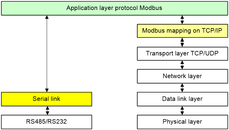
Modbus communication layer
Modbus supports deployment on a serial link or an Ethernet TCP/IP network. It utilizes network layers for communication in different networks as shown in Figure 1.
Figure 1 Modbus communication layer
Modbus communication mechanism
As shown in Figure 2, Modbus uses a client/server structure. In Modbus communication, only the client sends requests, and the server responds to the requests. Data is transmitted between the client and server over Modbus. On an industrial control network, PLC devices typically act as clients, and peripheral I/O sensors, valves, network drives, or other measuring devices act as servers.

Modbus data model
With the Modbus protocol, a Modbus client can perform read/write operations on the data stored in a Modbus server to perform data analysis and state control over the industrial network.
As shown in Figure 3, Modbus assigns logical address ranges for various device applications, with each application having a unique range. When the Modbus client requests data, it only needs to provide the Modbus server with the start address and the length of the desired data, and the server can then accurately send the requested data back to the client.
Figure 3 Communication mechanism
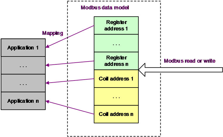
For information about Modbus-TCP address mappings for H3C devices, see "Appendix Modbus-TCP address mappings."
Modbus transmission messages
Modbus has two types of transmission messages, Modbus-RTU messages and Modbus-TCP messages.
Modbus-RTU messages
In Modbus-RTU transmission mode, the format of the Application Data Unit (ADU) uses the structure, as shown in Figure 4.
![]()
The fields in the Modbus-RTU ADU structure are as follows:
· Server address—Address of the server, which is the target of the Modbus request sent by the client. The address length is one byte.
· Function code—Instruction sent by the client to the server, such as reading/writing data from the server. The instruction length is one byte.
· Function-specific data—Describes the content of a specific request or response instruction based on different function codes. The data length varies.
· Error checking—Checks the correctness of the received data to avoid errors during message transmission. The filed length is two bytes.
Modbus-TCP messages
In Modbus-TCP transmission mode, the format of the Application Data Unit (ADU) uses the structure, as shown in Figure 5.
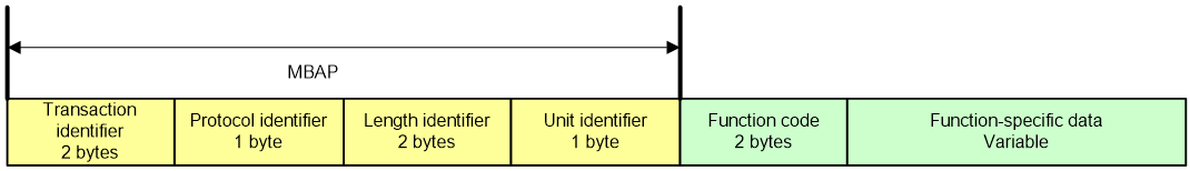
Different from Modbus messages transmitted over a serial link, the Modbus-TCP ADU does not require an error checking field, as the TCP/UDP protocols inherently provide error checking capabilities. In addition, the Modbus-TCP ADU no longer needs an address field; and addressing is achieved via encapsulation through the network and data link layers on the Ethernet network. To distinguish Modbus messages on the Ethernet network, a Modbus Application Header (MBAP) is encapsulated onto the PDU of the Modbus-TCP ADU. The fields in the Modbus-TCP ADU are as follows:
· Transaction identifier—Identifies the transaction of the Modbus request or response. The field length is two bytes.
· Protocol identifier—Value 0 identifies the Modbus protocol. The field length one byte.
· Length identifier—Identifies the subsequent field length. The field length is two bytes.
· Unit identifier—Used for system internal routing, identifying the remote servers connected via serial links or other buses, The field length is one byte.
· Function code—Instruction sent by the client to the server, such as reading/writing data from the server. The instruction length is one byte.
· Function-specific data—Describes the content of a specific request or response instruction based on different function codes. The data length varies.
Restrictions and guidelines: Modbus configuration
H3C industrial switches can act only as Modbus servers in a Modbus network.
This feature is not supported in an IRF fabric.
Enabling Modbus-TCP for the device
About this task
With this feature enabled, an H3C device can establish a TCP connection with a Modbus client and communicates with that client through Modbus-TPC. H3C devices uses port 502 to establish TCP connections with Modbus clients. H3C industrial switches can enable or disable a port and obtain port, ring network, and alarm information through Modbus-TCP.
By default, a Modbus client can read and write information from the device through Modbus TCP. Changing the device status without permission can pose a severe security risk. To address this issue, you can execute this command to set the operating mode of Modbus TCP on the device to read only, allowing Modbus clients to only read information from the device through Modbus TCP.
To obtain Modbus data addresses mapped to ports on devices, execute the display modbus-tcp information interface command.
Restrictions and guidelines
A Modbus client can read and edit the status of a maximum of 128 ports on an H3C device.
Procedure
1. Enter system view.
system-view
2. Enable Modbus-TCP for the device.
modbus-tcp enable
By default, Modbus-TCP is disabled for the device.
3. (Optional.) Set the operating mode of Modbus-TCP to read only.
modbus-tcp working-mode read-only
By default, Modbus-TCP operates in read write mode. The device can read its information and edit its status through Modbus-TCP.
Display and maintenance commands for Modbus
Execute display commands in any view.
|
Task |
Command |
|
Display information required for the device to read local port information using the Modbus-TCP protocol. |
display modbus-tcp information interface { interface-type interface-number | interface-name } |
Appendix Modbus-TCP address mappings
Device information (0X0000-0X0FFF)
|
Node name |
Start address (hex) |
Data length (Unit: words) |
Data type |
Description |
Example |
|
Company Name |
0x0000 |
255 |
ASCII |
Company name |
Company Name = “H3C” Word 0 Hi byte = ‘H’ Word 0 Lo byte = ‘3’ Word 1 Hi byte = ‘C’ Word 1 Lo byte = ‘\0’ Word 2 Hi byte = ‘\0’ Word 2 Lo byte = ‘\0’ |
|
Dev Type |
0x0100 |
255 |
ASCII |
Product name |
Device Type = “SWITCH” Word 0 Hi byte = ‘S’ Word 0 Lo byte = ‘W’ Word 1 Hi byte = ‘I’ Word 1 Lo byte = ‘T’ Word 2 Hi byte = ‘C’ Word 2 Lo byte = ‘H’ Word 3 Hi byte = ‘\0’ Word 3 Lo byte = ‘\0’ |
|
Company location |
0x0200 |
257 |
ASCII |
Company location |
Location = “Hangzhou, China” Word 0 Hi byte = ‘H’ Word 0 Lo byte = ‘a’ Word 1 Hi byte = ‘n’ Word 1 Lo byte = ‘g’ Word 2 Hi byte = ‘z’ Word 2 Lo byte = ‘h’ Word 3 Hi byte = ‘o’ Word 3 Lo byte = ‘u’ Word 4 Hi byte = ‘,’ Word 4 Lo byte = ‘ ’ (space) Word 5 Hi byte = ‘C’ Word 5 Lo byte = ‘h’ Word 6 Hi byte = ‘i’ Word 6 Lo byte = ‘n Word 7 Hi byte = ‘a’ Word 7 Lo byte = ‘\0’ Word 8 Hi byte = ‘\0’ Word 8 Lo byte = ‘\0’ |
|
Contact |
0x0400 |
257 |
ASCII |
Contact |
Contact = “New H3C Technologies Co., Ltd” Word 0 Hi byte = ‘N’ Word 0 Lo byte = ‘e’ Word 1 Hi byte = ‘w’ Word 1 Lo byte = ‘ ’ (space) Word 2 Hi byte = ‘H’ Word 2 Lo byte = ‘3’ Word 3 Hi byte = ‘C’ Word 3 Lo byte = ‘ ’ (space) Word 4 Hi byte = ‘T’ Word 4 Lo byte = ‘e’ Word 5 Hi byte = ‘c’ Word 5 Lo byte = ‘h’ Word 6 Hi byte = ‘n’ Word 6 Lo byte = ‘o’ Word 7 Hi byte = ‘l’ Word 7 Lo byte = ‘o’ Word 8 Hi byte = ‘g’ Word 8 Lo byte = ‘i Word 9 Hi byte = ‘e’ Word 9 Lo byte = ‘s’ Word 10 Hi byte = ‘ ’ (space) Word 10 Lo byte = ‘C’ Word 11 Hi byte = ‘o’ Word 11 Lo byte = ‘.’ Word 12 Hi byte = ‘,’ Word 12 Lo byte = ' '(space) Word 13 Hi byte = ‘L’ Word 13 Lo byte = ‘t’ Word 14 Hi byte = ‘d’ Word 14 Lo byte = ‘.’ Word 15 Hi byte = ‘\0’ Word 15 Lo byte = ‘\0’ |
|
Product Type |
0x0600 |
129 |
ASCII |
Product category |
Product Type = “H3C IE4320-52S” Word 0 Hi byte = ‘H’ Word 0 Lo byte = ‘3’ Word 1 Hi byte = ‘C’ Word 1 Lo byte = ‘ ’ (space) Word 2 Hi byte = ‘I’ Word 2 Lo byte = ‘E’ Word 3 Hi byte = ‘4’ Word 3 Lo byte = ‘3’ Word 4 Hi byte = ‘2’ Word 4 Lo byte = ‘0’ Word 5 Hi byte = ‘-’ Word 5 Lo byte = ‘5’ Word 6 Hi byte = ‘2’ Word 6 Lo byte = ‘S Word 7 Hi byte = ‘\0’ Word 7 Lo byte = ‘\0’ |
|
Serial Num |
0x0690 |
17 |
ASCII |
Serial number |
Serical Num = “219801A2DD9209Q00009” Word 0 Hi byte = ‘2’ Word 0 Lo byte = ‘1’ Word 1 Hi byte = ‘9’ Word 1 Lo byte = ‘8’ Word 2 Hi byte = ‘0’ Word 2 Lo byte = ‘1’ Word 3 Hi byte = ‘A’ Word 3 Lo byte = ‘2’ Word 4 Hi byte = ‘D’ Word 4 Lo byte = ‘D’ Word 5 Hi byte = ‘9’ Word 5 Lo byte = ‘2’ Word 6 Hi byte = ‘0’ Word 6 Lo byte = ‘9’ Word 7 Hi byte = ‘Q’ Word 7 Lo byte = ‘0’ Word 8 Hi byte = ‘0’ Word 8 Lo byte = ‘0’ Word 9 Hi byte = ‘0’ Word 9 Lo byte = ‘9’ Word 10 Hi byte = ‘\0’ Word 10 Lo byte = ‘\0’ |
|
Bootware Version |
0x06B0 |
32 |
ASCII |
BootWare version |
Bootware Version = “150” Word 0 Hi byte = ‘1’ Word 0 Lo byte = ‘5’ Word 1 Hi byte = ‘0’ Word 1 Lo byte = ‘\0’ Word 2 Hi byte = ‘\0’ Word 2 Lo byte = ‘\0’ |
|
Software Version |
0x06D0 |
32 |
ASCII |
Software version |
Bootware Version = “7.1.070 Release 6350” Word 0 Hi byte = ‘7’ Word 0 Lo byte = ‘.’ Word 1 Hi byte = ‘1’ Word 1 Lo byte = ‘.’ Word 2 Hi byte = ‘0’ Word 2 Lo byte = ‘7’ Word 3 Hi byte = ‘0’ Word 3 Lo byte = ‘ ’ Word 4 Hi byte = ‘R’ Word 4 Lo byte = ‘e’ Word 5 Hi byte = ‘l’ Word 5 Lo byte = ‘e’ Word 6 Hi byte = ‘a’ Word 6 Lo byte = ‘s’ Word 7 Hi byte = ‘e’ Word 7 Lo byte = ‘ ’ Word 8 Hi byte = ‘6’ Word 8 Lo byte = ‘3’ Word 9 Hi byte = ‘5’ Word 9 Lo byte = ‘0’ Word 10 Hi byte = ‘\0’ Word 10 Lo byte = ‘\0’ |
|
Hardware Version |
0x06F0 |
128 |
ASCII |
Hardware version |
Hardware Version = “Ver.A” Word 0 Hi byte = ‘V’ Word 0 Lo byte = ‘e’ Word 1 Hi byte = ‘r’ Word 1 Lo byte = ‘.’ Word 2 Hi byte = ‘A’ Word 2 Lo byte = ‘\0’ Word 3 Hi byte = ‘\0’ Word 3 Lo byte = ‘\0’ |
|
Logical Version |
0x0770 |
20 |
ASCII |
Logical version |
N/A |
|
IP Addr |
0x0800 |
2 |
HEX |
IP address |
IP address=1.2.3.4 Word 0 Hi byte = 0x01 Word 0 Lo byte = 0x02 Word 1 Hi byte = 0x03 Word 1 Lo byte = 0x04 |
|
Start Mac |
0x0802 |
3 |
HEX |
MAC address of the device |
MAC address=98F1-81CD-434A Word 0 Hi byte = 0x98 Word 0 Lo byte = 0xf1 Word 1 Hi byte = 0x81 Word 1 Lo byte = 0xcd Word 0 Hi byte = 0x43 Word 0 Lo byte = 0x4a |
|
MAC Number |
0x0805 |
2 |
HEX |
Number of MAC addresses of the MPU |
MAC quantity=56 Word 0 Hi byte = 0x00 Word 0 Lo byte = 0x00 Word 1 Hi byte = 0x00 Word 1 Lo byte = 0x38 |
|
Power1 State |
0x0807 |
1 |
HEX |
· 1—up · 0—down |
Power supply 1 status is up=1 Word 0 Hi byte = 0x00 Word 0 Lo byte = 0x00 |
|
Power2 State |
0x0808 |
1 |
HEX |
· 1—up · 0—down |
Power supply 1 status is down=0 Word 0 Hi byte = 0x00 Word 0 Lo byte = 0x01 |
|
Cpu Long Usage |
0x0809 |
2 |
HEX |
Average CPU usage (%) of the device in 5 minutes |
CPU usage=6% Word 0 Hi byte = 0x00 Word 0 Lo byte = 0x00 Word 1 Hi byte = 0x00 Word 1 Lo byte = 0x06 |
|
Cpu Short Usage |
0x080B |
2 |
HEX |
Average CPU usage (%) of the device in 1 minute |
CPU usage=4% Word 0 Hi byte = 0x00 Word 0 Lo byte = 0x00 Word 1 Hi byte = 0x00 Word 1 Lo byte = 0x04 |
|
Mem Size Total |
0x080D |
2 |
HEX |
Total memory size of the device (KB) |
Total memory size of the device=506408 Word 0 Hi byte = 0x00 Word 0 Lo byte = 0x07 Word 1 Hi byte = 0xba Word 1 Lo byte = 0x28 |
|
Mem Free |
0x080F |
2 |
HEX |
Free memory of the device (KB) |
Total memory size of the device=176376 Word 0 Hi byte = 0x00 Word 0 Lo byte = 0x02 Word 1 Hi byte = 0xb0 Word 1 Lo byte = 0xf8 |
|
Run Time |
0x0811 |
4 |
HEX |
Current time (UTC) |
Uptime=1357233936 Word 0 Hi byte = 0x00 Word 0 Lo byte = 0x00 Word 1 Hi byte = 0x00 Word 1 Lo byte = 0x00 Word 2 Hi byte = 0x50 Word 2 Lo byte = 0xe5 Word 3 Hi byte = 0xbf Word 3 Lo byte = 0x10 |
|
Run Time Total |
0x0815 |
4 |
HEX |
Total uptime of the device (min) |
Total uptime=982 Word 0 Hi byte = 0x00 Word 0 Lo byte = 0x00 Word 1 Hi byte = 0x00 Word 1 Lo byte = 0x00 Word 2 Hi byte = 0x00 Word 2 Lo byte = 0x00 Word 3 Hi byte = 0x03 Word 3 Lo byte = 0xd6 |
|
Temperature |
0x0819 |
2 |
HEX |
Device temperature (°C) |
N/A |
Port information (1-32) (0X1000-0X1FFF)
|
Node name |
Start address (hex) |
Data length (Unit: words) |
Data type |
Description |
Example |
|
IfName |
0x1000 |
32 |
ASCII |
Name of the port (length: 2-47) |
IfDescr = “GigabitEthernet2/0/2” Word 0 Hi byte = ‘G’ Word 0 Lo byte = ‘i’ Word 1 Hi byte = ‘g’ Word 1 Lo byte = ‘a’ Word 2 Hi byte = ‘b’ Word 2 Lo byte = ‘i’ Word 3 Hi byte = ‘t’ Word 3 Lo byte = ‘E’ Word 4 Hi byte = ‘t’ Word 4 Lo byte = ‘h’ Word 5 Hi byte = ‘e’ Word 5 Lo byte = ‘r’ Word 6 Hi byte = ‘n’ Word 6 Lo byte = ‘e’ Word 7 Hi byte = ‘t’ Word 7 Lo byte = ‘2’ Word 8 Hi byte = ‘/’ Word 8 Lo byte = ‘0’ Word 9 Hi byte = ‘/’ Word 9 Lo byte = ‘2’ Word 10 Hi byte = ‘\0’ Word 10 Lo byte = ‘\0’ |
|
IfStatus |
0x1040 |
1 |
HEX |
read: · 0—disable · 1—up · 2—down A port is enabled if it is in up or down state write: · 1—enable · 2—disable |
Port state down: Word 0 Hi byte = 0x00 Word 0 Lo byte = 0x01 |
|
IfSpeed |
0x1041 |
1 |
HEX |
· 0—Auto · 1—2Mbps · 2—10Mbps · 3—100Mbps · 4—155Mbps · 5—622bps · 6—1Gbps · 7—2Gbps · 8—2.5Gbps · 9—4Gbps · 10—5Gbps · 11—8Gbps · 12—10Gbps · 13—16Gbps · 14—20Gbps · 15—25Gbps · 16—32Gbps · 17—40Gbps · 18—100Gbps |
1G port speed: Word 0 Hi byte = 0x00 Word 0 Lo byte = 0x06 |
|
Duplex |
0x1042 |
1 |
HEX |
· 1—Full · 2—Half · 3—Auto |
Full duplex mode: Word 0 Hi byte = 0x00 Word 0 Lo byte = 0x01 |
|
FlowControl |
0x1043 |
1 |
HEX |
· 1—Enable · 2—Disable |
Flow control enabled: Word 0 Hi byte = 0x00 Word 0 Lo byte = 0x01 |
|
InPkts |
0x1044 |
4 |
HEX |
Number of received packets |
Total number of received packets on the port: 10359115 Word 0 Hi byte = 0x00 Word 0 Lo byte = 0x00 Word 0 Hi byte = 0x00 Word 0 Lo byte = 0x00 Word 0 Hi byte = 0x00 Word 0 Lo byte = 0x9e Word 0 Hi byte = 0x11 Word 0 Lo byte = 0x4b |
|
InOctets |
0x1048 |
4 |
HEX |
Number of received bytes (byte) |
Total number of received bytes: 1325966720 Word 0 Hi byte = 0x00 Word 0 Lo byte = 0x00 Word 0 Hi byte = 0x00 Word 0 Lo byte = 0x00 Word 0 Hi byte = 0x4F Word 0 Lo byte = 0x08 Word 0 Hi byte = 0xA5 Word 0 Lo byte = 0x80 |
|
OutPkts |
0x104C |
4 |
HEX |
Number of sent packets |
Number of sent packets: 21919 Word 0 Hi byte = 0x00 Word 0 Lo byte = 0x00 Word 0 Hi byte = 0x00 Word 0 Lo byte = 0x00 Word 0 Hi byte = 0x00 Word 0 Lo byte = 0x00 Word 0 Hi byte = 0x55 Word 0 Lo byte = 0x9F |
|
OutOctets |
0x1050 |
4 |
HEX |
Number of sent bytes (byte) |
Total number of sent bytes: 1470550 Word 0 Hi byte = 0x00 Word 0 Lo byte = 0x00 Word 0 Hi byte = 0x00 Word 0 Lo byte = 0x00 Word 0 Hi byte = 0x00 Word 0 Lo byte = 0x16 Word 0 Hi byte = 0x70 Word 0 Lo byte = 0x56 |
|
InUcastPkts |
0x1054 |
4 |
HEX |
Number of received unicast packets |
Number of received unicast packets: 5641988 Word 0 Hi byte = 0x00 Word 0 Lo byte = 0x00 Word 0 Hi byte = 0x00 Word 0 Lo byte = 0x00 Word 0 Hi byte = 0x00 Word 0 Lo byte = 0x56 Word 0 Hi byte = 0x17 Word 0 Lo byte = 0x04 |
|
InMulticastPkts |
0x1058 |
4 |
HEX |
Number of received multicast packets |
Number of received multicast packets: 2605221 Word 0 Hi byte = 0x00 Word 0 Lo byte = 0x00 Word 0 Hi byte = 0x00 Word 0 Lo byte = 0x00 Word 0 Hi byte = 0x00 Word 0 Lo byte = 0x27 Word 0 Hi byte = 0xC0 Word 0 Lo byte = 0xA5 |
|
InBrdcastPkts |
0x105C |
4 |
HEX |
Number of received broadcast packets |
Number of received broadcast packets: 2111906 Word 0 Hi byte = 0x00 Word 0 Lo byte = 0x00 Word 0 Hi byte = 0x00 Word 0 Lo byte = 0x00 Word 0 Hi byte = 0x00 Word 0 Lo byte = 0x20 Word 0 Hi byte = 0x39 Word 0 Lo byte = 0xA2 |
|
OutUcastPkts |
0x1060 |
4 |
HEX |
Number of sent unicast packets |
Number of sent unicast packets: 21234 Word 0 Hi byte = 0x00 Word 0 Lo byte = 0x00 Word 0 Hi byte = 0x00 Word 0 Lo byte = 0x00 Word 0 Hi byte = 0x00 Word 0 Lo byte = 0x00 Word 0 Hi byte = 0x52 Word 0 Lo byte = 0xF2 |
|
OutMulticastPkts |
0x1064 |
4 |
HEX |
Number of sent multicast packets |
Number of sent multicast packets: 4998 Word 0 Hi byte = 0x00 Word 0 Lo byte = 0x00 Word 0 Hi byte = 0x00 Word 0 Lo byte = 0x00 Word 0 Hi byte = 0x00 Word 0 Lo byte = 0x00 Word 0 Hi byte = 0x13 Word 0 Lo byte = 0x86 |
|
OutBrdcastPkts |
0x1068 |
4 |
HEX |
Number of sent broadcast packets |
Number sent broadcast packets: 3329 Word 0 Hi byte = 0x00 Word 0 Lo byte = 0x00 Word 0 Hi byte = 0x00 Word 0 Lo byte = 0x00 Word 0 Hi byte = 0x00 Word 0 Lo byte = 0x00 Word 0 Hi byte = 0x0D Word 0 Lo byte = 0x01 |
|
InPauses |
0x106C |
4 |
HEX |
Number of received pause frames |
Number of received pause frames: 680 Word 0 Hi byte = 0x00 Word 0 Lo byte = 0x00 Word 0 Hi byte = 0x00 Word 0 Lo byte = 0x00 Word 0 Hi byte = 0x00 Word 0 Lo byte = 0x00 Word 0 Hi byte = 0x02 Word 0 Lo byte = 0xA8 |
|
OutPauses |
0x1070 |
4 |
HEX |
Number of sent pause frames |
Number of sent pause frames: 680 Word 0 Hi byte = 0x00 Word 0 Lo byte = 0x00 Word 0 Hi byte = 0x00 Word 0 Lo byte = 0x00 Word 0 Hi byte = 0x00 Word 0 Lo byte = 0x00 Word 0 Hi byte = 0x02 Word 0 Lo byte = 0xA8 |
|
InErrCRCFrames |
0x1074 |
4 |
HEX |
Number of received CRC error packets |
Number of received CRC error packets: 2872808 Word 0 Hi byte = 0x00 Word 0 Lo byte = 0x00 Word 0 Hi byte = 0x00 Word 0 Lo byte = 0x00 Word 0 Hi byte = 0x00 Word 0 Lo byte = 0x2B Word 0 Hi byte = 0xD5 Word 0 Lo byte = 0xE8 |
|
|
NOTE: · The start port ID is 1. · The node data address for each port (1-32) = node start address + 0x80 * (port ID - start port ID). |
Port information (33-64) (0X2000-0X2FFF)
|
Node name |
Start address (hex) |
Data length (Unit: words) |
Data type |
Description |
Example |
|
IfDescr |
0x2000 |
32 |
ASCII |
Name of the port (length: 2 to 47) |
IfDescr = “GigabitEthernet2/0/2” Word 0 Hi byte = ‘G’ Word 0 Lo byte = ‘i’ Word 1 Hi byte = ‘g’ Word 1 Lo byte = ‘a’ Word 2 Hi byte = ‘b’ Word 2 Lo byte = ‘i’ Word 3 Hi byte = ‘t’ Word 3 Lo byte = ‘E’ Word 4 Hi byte = ‘t’ Word 4 Lo byte = ‘h’ Word 5 Hi byte = ‘e’ Word 5 Lo byte = ‘r’ Word 6 Hi byte = ‘n’ Word 6 Lo byte = ‘e’ Word 7 Hi byte = ‘t’ Word 7 Lo byte = ‘2’ Word 8 Hi byte = ‘/’ Word 8 Lo byte = ‘0’ Word 9 Hi byte = ‘/’ Word 9 Lo byte = ‘2’ Word 10 Hi byte = ‘\0’ Word 10 Lo byte = ‘\0’ |
|
IfStatus |
0x2040 |
1 |
HEX |
read: · 0—disable · 1—up · 2—down A port is enabled if it is in up or down state write: · 1—enable · 2—disable |
N/A |
|
IfSpeed |
0x2041 |
1 |
HEX |
· 0—Auto · 1—2Mbps · 2—10Mbps · 3—100Mbps · 4—155Mbps · 5—622bps · 6—1Gbps · 7—2Gbps · 8—2.5Gbps · 9—4Gbps · 10—5Gbps · 11—8Gbps · 12—10Gbps · 13—16Gbps · 14—20Gbps · 15—25Gbps · 16—32Gbps · 17—40Gbps · 18—100Gbps |
N/A |
|
Duplex |
0x2042 |
1 |
HEX |
· 1—Full · 2—Half · 3—Auto |
N/A |
|
FlowControl |
0x2043 |
1 |
HEX |
Enable flow control · 2—Disable · 3—Only enable flow control packet receiving |
N/A |
|
InPkts |
0x2044 |
4 |
HEX |
Number of received packets |
N/A |
|
Number of received bytes InOctets |
0x2048 |
4 |
HEX |
Number of received bytes |
N/A |
|
OutPkts |
0x204C |
4 |
HEX |
Number of sent packets |
N/A |
|
OutOctets |
0x2050 |
4 |
HEX |
Number of sent bytes |
N/A |
|
InUcastPkts |
0x2054 |
4 |
HEX |
Number of received unicast packets |
N/A |
|
InMulticastPkts |
0x2058 |
4 |
HEX |
Number of received multicast packets |
N/A |
|
InBrdcastPkts |
0x205C |
4 |
HEX |
Number of received broadcast packets |
N/A |
|
OutUcastPkts |
0x2060 |
4 |
HEX |
Number of sent unicast packets |
N/A |
|
OutMulticastPkts |
0x2064 |
4 |
HEX |
Number of sent multicast packets |
N/A |
|
OutBrdcastPkts |
0x2068 |
4 |
HEX |
Number of sent broadcast packets |
N/A |
|
InPauses |
0x206C |
4 |
HEX |
Number of received pause frames |
N/A |
|
OutPauses |
0x2070 |
4 |
HEX |
Number of sent pause frames |
N/A |
|
InErrCRCFrames |
0x2074 |
4 |
HEX |
Number of received CRC error packets |
N/A |
|
|
NOTE: · The start port ID is 33. · The node data address for each port (33-64) = node start address + 0x80 * (port ID - start port ID). |
Port information (65-96) (0X3000-0X3FFF)
|
Node name |
Start address (hex) |
Data length (Unit: words) |
Data type |
Description |
Example |
|
IfName |
0x3000 |
32 |
ASCII |
Name of the port (length: 2 to 47) |
IfDescr = “GigabitEthernet2/0/2” Word 0 Hi byte = ‘G’ Word 0 Lo byte = ‘i’ Word 1 Hi byte = ‘g’ Word 1 Lo byte = ‘a’ Word 2 Hi byte = ‘b’ Word 2 Lo byte = ‘i’ Word 3 Hi byte = ‘t’ Word 3 Lo byte = ‘E’ Word 4 Hi byte = ‘t’ Word 4 Lo byte = ‘h’ Word 5 Hi byte = ‘e’ Word 5 Lo byte = ‘r’ Word 6 Hi byte = ‘n’ Word 6 Lo byte = ‘e’ Word 7 Hi byte = ‘t’ Word 7 Lo byte = ‘2’ Word 8 Hi byte = ‘/’ Word 8 Lo byte = ‘0’ Word 9 Hi byte = ‘/’ Word 9 Lo byte = ‘2’ Word 10 Hi byte = ‘\0’ Word 10 Lo byte = ‘\0’ |
|
IfStatus |
0x3040 |
1 |
HEX |
read: · 0—disable · 1—up · 2—down A port is enabled is in up or down state. write: · 1—enable · 2—disable. |
Port state down: Word 0 Hi byte = 0x00 Word 0 Lo byte = 0x01 |
|
IfSpeed |
0x3041 |
1 |
HEX |
· 0—Auto · 1—2Mbps · 2—10Mbps · 3—100Mbps · 4—155Mbps · 5—622bps · 6—1Gbps · 7—2Gbps · 8—2.5Gbps · 9—4Gbps · 10—5Gbps · 11—8Gbps · 12—10Gbps · 13—16Gbps · 14—20Gbps · 15—25Gbps · 16—32Gbps · 17—40Gbps · 18—100Gbps |
1G port speed: Word 0 Hi byte = 0x00 Word 0 Lo byte = 0x06 |
|
Duplex |
0x3042 |
1 |
HEX |
· 1—Full · 2—Half · 3—Auto |
Full duplex mode: Word 0 Hi byte = 0x00 Word 0 Lo byte = 0x01 |
|
FlowControl |
0x3043 |
1 |
HEX |
· 1—Enable · 2—Disable |
Flow control enabled: Word 0 Hi byte = 0x00 Word 0 Lo byte = 0x01 |
|
InPkts |
0x3044 |
4 |
HEX |
Number of received packets |
Total number of received packets: 10359115 Word 0 Hi byte = 0x00 Word 0 Lo byte = 0x00 Word 0 Hi byte = 0x00 Word 0 Lo byte = 0x00 Word 0 Hi byte = 0x00 Word 0 Lo byte = 0x9e Word 0 Hi byte = 0x11 Word 0 Lo byte = 0x4b |
|
InOctets |
0x3048 |
4 |
HEX |
Number of received bytes (byte) |
Total number of received bytes: 1325966720 Word 0 Hi byte = 0x00 Word 0 Lo byte = 0x00 Word 0 Hi byte = 0x00 Word 0 Lo byte = 0x00 Word 0 Hi byte = 0x4F Word 0 Lo byte = 0x08 Word 0 Hi byte = 0xA5 Word 0 Lo byte = 0x80 |
|
OutPkts |
0x304C |
4 |
HEX |
Number of sent packets |
Number of sent packets: 21919 Word 0 Hi byte = 0x00 Word 0 Lo byte = 0x00 Word 0 Hi byte = 0x00 Word 0 Lo byte = 0x00 Word 0 Hi byte = 0x00 Word 0 Lo byte = 0x00 Word 0 Hi byte = 0x55 Word 0 Lo byte = 0x9F |
|
OutOctets |
0x3050 |
4 |
HEX |
Number of sent bytes (byte) |
Total number of sent bytes: 1470550 Word 0 Hi byte = 0x00 Word 0 Lo byte = 0x00 Word 0 Hi byte = 0x00 Word 0 Lo byte = 0x00 Word 0 Hi byte = 0x00 Word 0 Lo byte = 0x16 Word 0 Hi byte = 0x70 Word 0 Lo byte = 0x56 |
|
InUcastPkts |
0x3054 |
4 |
HEX |
Number of received unicast packets |
Number of received unicast packets: 5641988 Word 0 Hi byte = 0x00 Word 0 Lo byte = 0x00 Word 0 Hi byte = 0x00 Word 0 Lo byte = 0x00 Word 0 Hi byte = 0x00 Word 0 Lo byte = 0x56 Word 0 Hi byte = 0x17 Word 0 Lo byte = 0x04 |
|
InMulticastPkts |
0x3058 |
4 |
HEX |
Number of received multicast packets |
Number of received multicast packets: 2605221 Word 0 Hi byte = 0x00 Word 0 Lo byte = 0x00 Word 0 Hi byte = 0x00 Word 0 Lo byte = 0x00 Word 0 Hi byte = 0x00 Word 0 Lo byte = 0x27 Word 0 Hi byte = 0xC0 Word 0 Lo byte = 0xA5 |
|
InBrdcastPkts |
0x305C |
4 |
HEX |
Number of received broadcast packets |
Number of received broadcast packets: 2111906 Word 0 Hi byte = 0x00 Word 0 Lo byte = 0x00 Word 0 Hi byte = 0x00 Word 0 Lo byte = 0x00 Word 0 Hi byte = 0x00 Word 0 Lo byte = 0x20 Word 0 Hi byte = 0x39 Word 0 Lo byte = 0xA2 |
|
OutUcastPkts |
0x3060 |
4 |
HEX |
Number of sent unicast packets |
Number of sent unicast packets: 21234 Word 0 Hi byte = 0x00 Word 0 Lo byte = 0x00 Word 0 Hi byte = 0x00 Word 0 Lo byte = 0x00 Word 0 Hi byte = 0x00 Word 0 Lo byte = 0x00 Word 0 Hi byte = 0x52 Word 0 Lo byte = 0xF2 |
|
OutMulticastPkts |
0x3064 |
4 |
HEX |
Number of sent multicast packets |
Number of sent multicast packets: 4998 Word 0 Hi byte = 0x00 Word 0 Lo byte = 0x00 Word 0 Hi byte = 0x00 Word 0 Lo byte = 0x00 Word 0 Hi byte = 0x00 Word 0 Lo byte = 0x00 Word 0 Hi byte = 0x13 Word 0 Lo byte = 0x86 |
|
OutBrdcastPkts |
0x3068 |
4 |
HEX |
Number of sent broadcast packets |
Number sent broadcast packets: 3329 Word 0 Hi byte = 0x00 Word 0 Lo byte = 0x00 Word 0 Hi byte = 0x00 Word 0 Lo byte = 0x00 Word 0 Hi byte = 0x00 Word 0 Lo byte = 0x00 Word 0 Hi byte = 0x0D Word 0 Lo byte = 0x01 |
|
InPauses |
0x306C |
4 |
HEX |
Number of received pause frames |
Number of received pause frames: 680 Word 0 Hi byte = 0x00 Word 0 Lo byte = 0x00 Word 0 Hi byte = 0x00 Word 0 Lo byte = 0x00 Word 0 Hi byte = 0x00 Word 0 Lo byte = 0x00 Word 0 Hi byte = 0x02 Word 0 Lo byte = 0xA8 |
|
OutPauses |
0x3070 |
4 |
HEX |
Number of sent pause frames |
Number of sent pause frames: 680 Word 0 Hi byte = 0x00 Word 0 Lo byte = 0x00 Word 0 Hi byte = 0x00 Word 0 Lo byte = 0x00 Word 0 Hi byte = 0x00 Word 0 Lo byte = 0x00 Word 0 Hi byte = 0x02 Word 0 Lo byte = 0xA8 |
|
InErrCRCFrames |
0x3074 |
4 |
HEX |
Number of received CRC error packets |
Number of received CRC error packets: 2872808 Word 0 Hi byte = 0x00 Word 0 Lo byte = 0x00 Word 0 Hi byte = 0x00 Word 0 Lo byte = 0x00 Word 0 Hi byte = 0x00 Word 0 Lo byte = 0x2B Word 0 Hi byte = 0xD5 Word 0 Lo byte = 0xE8 |
|
|
NOTE: · The start port ID is 65. · The node data address for each port (65-96) = node start address + 0x80 * (port ID - start port ID). |
Port information (97-128) (0X4000-0X4FFF)
|
Node name |
Start address (hex) |
Data length (Unit: words) |
Data type |
Description |
Example |
|
IfDescr |
0x4000 |
32 |
ASCII |
Name of the port (length: 2 to 47) |
IfDescr = “GigabitEthernet2/0/2” Word 0 Hi byte = ‘G’ Word 0 Lo byte = ‘i’ Word 1 Hi byte = ‘g’ Word 1 Lo byte = ‘a’ Word 2 Hi byte = ‘b’ Word 2 Lo byte = ‘i’ Word 3 Hi byte = ‘t’ Word 3 Lo byte = ‘E’ Word 4 Hi byte = ‘t’ Word 4 Lo byte = ‘h’ Word 5 Hi byte = ‘e’ Word 5 Lo byte = ‘r’ Word 6 Hi byte = ‘n’ Word 6 Lo byte = ‘e’ Word 7 Hi byte = ‘t’ Word 7 Lo byte = ‘2’ Word 8 Hi byte = ‘/’ Word 8 Lo byte = ‘0’ Word 9 Hi byte = ‘/’ Word 9 Lo byte = ‘2’ Word 10 Hi byte = ‘\0’ Word 10 Lo byte = ‘\0’ |
|
IfStatus |
0x4040 |
1 |
HEX |
read: · 0—disable · 1—up · 2—down A port is enabled is in up or down state. write: · 1—enable · 2—disable. |
N/A |
|
IfSpeed |
0x4041 |
1 |
HEX |
· 0—Auto · 1—2Mbps · 2—10Mbps · 3—100Mbps · 4—155Mbps · 5—622bps · 6—1Gbps · 7—2Gbps · 8—2.5Gbps · 9—4Gbps · 10—5Gbps · 11—8Gbps · 12—10Gbps · 13—16Gbps · 14—20Gbps · 15—25Gbps · 16—32Gbps · 17—40Gbps · 18—100Gbps |
N/A |
|
Duplex |
0x4042 |
1 |
HEX |
· 1—Full · 2—Half · 3—Auto |
N/A |
|
FlowControl |
0x4043 |
1 |
HEX |
Enable flow control · 2—Disable · 3—Only enable flow control packet receiving |
N/A |
|
InPkts |
0x4044 |
4 |
HEX |
Number of received packets |
N/A |
|
InOctets |
0x4048 |
4 |
HEX |
Number of received bytes |
N/A |
|
OutPkts |
0x404C |
4 |
HEX |
Number of sent packets |
N/A |
|
OutOctets |
0x4050 |
4 |
HEX |
Number of sent bytes |
N/A |
|
InUcastPkts |
0x4054 |
4 |
HEX |
Number of received unicast packets |
N/A |
|
InMulticastPkts |
0x4058 |
4 |
HEX |
Number of received multicast packets |
N/A |
|
InBrdcastPkts |
0x405C |
4 |
HEX |
Number of received broadcast packets |
N/A |
|
OutUcastPkts |
0x4060 |
4 |
HEX |
Number of sent unicast packets |
N/A |
|
OutMulticastPkts |
0x4064 |
4 |
HEX |
Number of sent multicast packets |
N/A |
|
OutBrdcastPkts |
0x4068 |
4 |
HEX |
Number of sent broadcast packets |
N/A |
|
InPauses |
0x406C |
4 |
HEX |
Number of received pause frames |
N/A |
|
OutPauses |
0x4070 |
4 |
HEX |
Number of sent pause frames |
N/A |
|
InErrCRCFrames |
0x4074 |
4 |
HEX |
Number of received CRC error packets |
N/A |
|
|
NOTE: · The start port ID is 97. · The node data address for each port (97-128) = node start address + 0x80 * (port ID - start port ID). |
Alarm information (0X5000-0X5FFF)
|
Node name |
Start address (hex) |
Data length Unit: words |
Data type |
Description |
Example |
Remarks |
|
Port Status Alarm |
0x5000 |
1 |
HEX |
· 0—disable · 1—normal · 2—alarm |
Normal state Word 0 Hi byte = 0x00 Word 0 Lo byte = 0x01 |
The alarm data length for each port is 0x10. The start port ID is 1. The alarm node data address for each port (1-128) = node start address + 0x10 * (port ID - start port ID). |
|
Port Input Alarm |
0x5001 |
1 |
HEX |
· 1—normal. · 2—alarm |
Normal state Word 0 Hi byte = 0x00 Word 0 Lo byte = 0x01 |
|
|
Port Output Alarm |
0x5002 |
1 |
HEX |
· 1—normal. · 2—alarm |
Normal state Word 0 Hi byte = 0x00 Word 0 Lo byte = 0x01 |
|
|
Port Crc Alarm |
0x5003 |
1 |
HEX |
· 1—normal. · 2—alarm |
Normal state Word 0 Hi byte = 0x00 Word 0 Lo byte = 0x01 |
|
|
Temperature Alarm |
0x5800 |
1 |
HEX |
· 1—normal. · 2—alarm |
Normal state Word 0 Hi byte = 0x00 Word 0 Lo byte = 0x01 |
N/A |
|
Cpu Usage Alarm |
0x5801 |
1 |
HEX |
· 1—normal. · 2—alarm |
Normal state Word 0 Hi byte = 0x00 Word 0 Lo byte = 0x01 |
N/A |
|
Mem Usage Alarm |
0x5802 |
1 |
HEX |
· 1—normal. · 2—alarm |
Normal state Word 0 Hi byte = 0x00 Word 0 Lo byte = 0x01 |
N/A |
|
Power Status Alarm |
0x5803 |
1 |
HEX |
· 0—disable · 1—normal. · 2—Alarm for power supply 1 · 3—Alarm for power supply 2 |
Normal state Word 0 Hi byte = 0x00 Word 0 Lo byte = 0x01 |
N/A |
|
|
NOTE: · The start port ID is 1. · The alarm node data address for each port (1-128) = alarm node start address + 0x10 * (port ID - start port ID). |
RSTP information (0X6000-0X6FFF)
|
Node name |
Start address (hex) |
Data length Unit: words |
Data type |
Description |
Example |
Remarks |
|
RSTP_PROTOCOL_STATUS |
0x6000 |
1 |
HEX |
· 0—disable · 1—enable |
Normal state Word 0 Hi byte = 0x00 Word 0 Lo byte = 0x01 |
N/A |
|
RSTP_ROOTBRIAGE_ID |
0x6001 |
4 |
HEX |
Root bridge ID 8 bytes |
RootId=0x80004CB302A30100 Word 0 Hi byte = 0x80 Word 0 Lo byte = 0x00 Word 1 Hi byte = 0x4c Word 1 Lo byte = 0xb3 Word 2 Hi byte = 0x02 Word 2 Lo byte = 0xa3 Word 3 Hi byte = 0x01 Word 3 Lo byte = 0x00 |
N/A |
|
RSTP_BRIAGE_ID |
0x6005 |
4 |
HEX |
Network bridge ID 8 bytes |
BridgeId=0x80004CB302A30100 Word 0 Hi byte = 0x80 Word 0 Lo byte = 0x00 Word 1 Hi byte = 0x4c Word 1 Lo byte = 0xb3 Word 2 Hi byte = 0x02 Word 2 Lo byte = 0xa3 Word 3 Hi byte = 0x01 Word 3 Lo byte = 0x00 |
N/A |
|
RSTP_PRIORITY |
0x6009 |
2 |
HEX |
Priority, in the range of o to 61440 |
Priority=32768 Word 0 Hi byte = 0x00 Word 0 Lo byte = 0x00 Word 1 Hi byte = 0x80 Word 1 Lo byte = 0x00 |
N/A |
|
RSTP_HELLO_TIME |
0x600B |
2 |
HEX |
Interval for the root device to send BPDUs, in the range of 1 to 10 |
HelloTime=2 Word 0 Hi byte = 0x00 Word 0 Lo byte = 0x00 Word 1 Hi byte = 0x00 Word 1 Lo byte = 0x02 |
N/A |
|
RSTP_MAX_AGE_TIME |
0x600D |
2 |
HEX |
Max age timer for BPDUs, in the range of 6 to 40 |
MaxAge = 20 Word 0 Hi byte = 0x00 Word 0 Lo byte = 0x00 Word 1 Hi byte = 0x00 Word 1 Lo byte = 0x14 |
N/A |
|
RSTP_FORWARD_DELAY_TIME |
0x600F |
2 |
HEX |
Forward delay timer, in the range of 4 to 30 |
ForwardDelay = 15 Word 0 Hi byte = 0x00 Word 0 Lo byte = 0x00 Word 1 Hi byte = 0x00 Word 1 Lo byte = 0x0f |
N/A |
|
RSTP_PORT_PROTOCOL_STATUS |
0x6020 |
1 |
HEX |
· 0—disable · 1—enable |
Enabling state Word 0 Hi byte = 0x00 Word 0 Lo byte = 0x01 |
The data length for each port is 0x10. The start port ID is 1. The node data address for each port (1-128) = node start address + 0x10 * (port ID - start port ID). |
|
RSTP_PORT_PRIORITY |
0x6021 |
2 |
HEX |
Port priority, in the range of o to 240 |
Priority = 128 Word 0 Hi byte = 0x00 Word 0 Lo byte = 0x00 Word 0 Hi byte = 0x00 Word 0 Lo byte = 0x80 |
|
|
RSTP_PATH_COST |
0x6023 |
2 |
HEX |
Path cost, in the range of 0 to 200000000 |
PathCost = 0 Word 0 Hi byte = 0x00 Word 0 Lo byte = 0x00 Word 0 Hi byte = 0x00 Word 0 Lo byte = 0x00 |
|
|
RSTP_PORT_ROLE |
0x6025 |
2 |
HEX |
· 0—Disabled port · 1—Alternate port · 2—Backup port · 3—Root port · 4—Designated port · 5—Master port |
Role = 4 Word 0 Hi byte = 0x00 Word 0 Lo byte = 0x00 Word 0 Hi byte = 0x00 Word 0 Lo byte = 0x04 |
|
|
RSTP_PORT_STATUS |
0x6027 |
2 |
HEX |
· 1—Discarding · 2—Learning · 3—Forwarding |
State = 3 Word 0 Hi byte = 0x00 Word 0 Lo byte = 0x00 Word 0 Hi byte = 0x00 Word 0 Lo byte = 0x03 |
|
|
NOTE: · The start port ID is 1. · The STP data address for each port (1-128) = node start address + 0x10 * (port ID - start port ID). |
ERPS information (1-7) (0X7000-0x7FFF)
|
Node name |
Start address (hex) |
Data length Unit: words |
Data type |
Description |
Remarks |
|
MODBUS_REG_ADDR_ERPS_PROTOCOL_STATUS |
0x7000 |
1 |
HEX |
· 0—disable · 1—enable |
N/A |
|
ERPS ring ID MODBUS_REG_ADDR_ERPS_RING_ID |
0x7001 |
1 |
HEX |
The ID is in the range of 1 to 8. |
The data length for each ERPS ring is 0x243. The start ring ID is 1. The node data address for each ERPS ring = node start address + 0x243 * (ring ID - start ring ID). |
|
MODBUS_REG_ADDR_ERPS_PORT0 |
0x7002 |
1 |
HEX |
N/A |
N/A |
|
ERPS ring member port MODBUS_REG_ADDR_ERPS_PORT1 |
0x7003 |
1 |
HEX |
N/A |
N/A |
|
MODBUS_REG_ADDR_ERPS_INSTANCE_ID |
0x7004 |
1 |
HEX |
Value range: 1 to 64 |
The data length for each ERPS instance is 0x9. The start ring ID is 1. The start instance ID is 1. The node data address for each ERPS instance = node start address + 0x243 * (ring ID - start ring ID) + 0x9 * (instance ID - start instance ID). |
|
MODBUS_REG_ADDR_ERPS_CONTROL_VLAN |
0x7005 |
1 |
HEX |
Value range: 2 to 4094. |
N/A |
|
MODBUS_REG_ADDR_ERPS_NODE_ROLE |
0x7006 |
1 |
HEX |
· 0—owner · 1—neighbor · 2—normal · 3—interconnection |
N/A |
|
MODBUS_REG_ADDR_ERPS_NODE_STATE |
0x7007 |
1 |
HEX |
· 0—Undefined · 1—init · 2—idle · 3—protection · 4—MS · 5—FS · 6—Pending |
N/A |
|
MODBUS_REG_ADDR_ERPS_INSTANCE_ENABLE_STATUS |
0x7008 |
1 |
HEX |
· 0—false · 1—true |
N/A |
|
MODBUS_REG_ADDR_ERPS_PORT0_PORT_ROLE |
0x7009 |
1 |
HEX |
· 0—RPL · 1—Non-RPL · 2—Undefined |
N/A |
|
MODBUS_REG_ADDR_ERPS_PORT0_PORT_STATUS |
0x700A |
1 |
HEX |
· 0—Block · 1—Up · 2—Down · 3—Undefined |
N/A |
|
MODBUS_REG_ADDR_ERPS_PORT1 |
0x700B |
1 |
HEX |
Value range: 1 to 128 |
N/A |
|
MODBUS_REG_ADDR_ERPS_PORT1_PORT_STATUS |
0x700C |
1 |
HEX |
· 0—Block · 1—Up · 2—Down · 3—Undefined |
N/A |
|
|
NOTE: · The start ring ID and instance ID are both 1. · The node data address for each ring = node start address + 0x243 * (ring ID - start ring ID). · The node address for an instance = node start address + (0x243 * (ring ID - start ring ID)) + (0x9 * (instance ID - start instanceID)). |
ERPS ring information (8) (0X7000-0x8FFF)
|
Node name |
Start address (hex) |
Data length Unit: words |
Data type |
Description |
Remarks |
|
MODBUS_REG_ADDR_ERPS_RING_ID |
0x8001 |
1 |
HEX |
The ID is in the range of 1 to 8. |
The data length for each ERPS ring is 0x243. The start ring ID is 8. The node data address for each ERPS ring = node start address + 0x243 * (ring ID - start ring ID). |
|
MODBUS_REG_ADDR_ERPS_PORT0 |
0x8002 |
1 |
HEX |
N/A |
N/A |
|
MODBUS_REG_ADDR_ERPS_PORT1 |
0x8003 |
1 |
HEX |
N/A |
N/A |
|
MODBUS_REG_ADDR_ERPS_INSTANCE_ID |
0x8004 |
1 |
HEX |
Value range: 1 to 64 |
The data length for each ERPS instance is 0x9. The start ring ID is 8. The start instance ID is 1. The node data address for each ERPS instance = node start address + 0x243 * (ring ID - start ring ID) + 0x9 * (instance ID - start instance ID). |
|
MODBUS_REG_ADDR_ERPS_CONTROL_VLAN |
0x8005 |
1 |
HEX |
Value range: 2 to 4094 |
N/A |
|
MODBUS_REG_ADDR_ERPS_NODE_ROLE |
0x8006 |
1 |
HEX |
· 0—owner · 1—neighbor · 2—normal · 3—interconnection |
N/A |
|
MODBUS_REG_ADDR_ERPS_NODE_STATE |
0x8007 |
1 |
HEX |
· 0—Undefined · 1—init · 2—idle · 3—protection · 4—MS · 5—FS · 6—Pending |
N/A |
|
MODBUS_REG_ADDR_ERPS_INSTANCE_ENABLE_STATUS |
0x8008 |
1 |
HEX |
· 0—false · 1—true |
N/A |
|
MODBUS_REG_ADDR_ERPS_PORT0_PORT_ROLE |
0x8009 |
1 |
HEX |
· 0—RPL. · 1—Non-RPL. · 2—Undefined |
N/A |
|
MODBUS_REG_ADDR_ERPS_PORT0_PORT_STATUS |
0x800A |
1 |
HEX |
· 0—Block · 1—Up · 2—Down · 3—Undefined |
N/A |
|
MODBUS_REG_ADDR_ERPS_PORT1 |
0x800B |
1 |
HEX |
Value range: 1 to 128 |
N/A |
|
MODBUS_REG_ADDR_ERPS_PORT1_PORT_STATUS |
0x800C |
1 |
HEX |
· 0—Block · 1—Up · 2—Down · 3—Undefined |
N/A |
|
|
NOTE: · The start ring ID is 8 and the start instance ID is 1. · The node data address for each ring = node start address + 0x243 * (ring ID - start ring ID). · The node address for an ERPS instance = node start address + (0x243 * (ring ID - start ring ID) ) + (0x9 * (instance ID - start instance ID)). |
RRPP information (1-2) (0X9000-0x9FFF)
|
Node name |
Start address (hex) |
Data length Unit: words |
Data type |
Description |
Remarks |
|
MODBUS_REG_ADDR_RRPP_PROTOCOL_STATUS |
0x9000 |
1 |
HEX |
· 0—disable · 1—enable |
N/A |
|
MODBUS_REG_ADDR_RRPP_DOMAIN_ID |
0x9001 |
1 |
HEX |
Value range: 1 to 8 |
The data length for each RRPP domain is 0x582. The start domain ID is 1. The node data address for each domain = node start address + 0x582 * (domain ID - start domain ID). |
|
MODBUS_REG_ADDR_RRPP_CONTROL_VLAN |
0x9002 |
1 |
HEX |
Value range: 2 to 4094 |
N/A |
|
MODBUS_REG_ADDR_RRPP_RING_ID |
0x9003 |
1 |
HEX |
Value range: 1 to 128 |
The data length for each RRPP ring is 0xB. The start domain ID is 1. The start ring ID is 1. The node data address for each RRPP ring = node start address + 0x582 * (domain ID - start domain ID) + 0xB * (ring ID - start ring ID). |
|
MODBUS_REG_ADDR_RRPP_NODE_MODE |
0x9004 |
1 |
HEX |
· 0—transit · 1—master · 2—edge · 3—assistant edge |
N/A |
|
MODBUS_REG_ADDR_RRPP_PRIMARY_PORT |
0x9005 |
1 |
HEX |
Value range: 1 to 128 |
N/A |
|
MODBUS_REG_ADDR_RRPP_PRIMARY_PORT_STATUS |
0x9006 |
1 |
HEX |
· 0—down · 1—up · 2—blocked |
N/A |
|
MODBUS_REG_ADDR_RRPP_SECONDARY_PORT |
0x9007 |
1 |
HEX |
Value range: 1 to 128 |
N/A |
|
MODBUS_REG_ADDR_RRPP_SECONDARY_PORT_STATUS |
0x9008 |
1 |
HEX |
· 0—down · 1—up · 2—blocked |
N/A |
|
MODBUS_REG_ADDR_RRPP_EDGE_PORT |
0x9009 |
1 |
HEX |
Value range: 1 to 128 |
N/A |
|
MODBUS_REG_ADDR_RRPP_EDGE_PORT_STATUS |
0x900A |
1 |
HEX |
· 0—down · 1—up · 2—blocked |
N/A |
|
MODBUS_REG_ADDR_RRPP_RING_LEVEL |
0x900B |
1 |
HEX |
· 0—major ring · 1—sub ring |
N/A |
|
MODBUS_REG_ADDR_RRPP_RING_ENABLE |
0x900C |
1 |
HEX |
· 0—false · 1—true |
N/A |
|
MODBUS_REG_ADDR_RRPP_RING_STATE |
0x900D |
1 |
HEX |
· 0—Completed · 1—Failed · 2—LinkUp · 3—LinkDown · 4—PreForward · 5—LinkUpNotify · 6—LinkDnNotify · 7—PreForwardNotify · 8—Unknown |
N/A |
|
|
NOTE: · The start domain ID and start instance ID are both 1. · The node data address for each domain = node start address + 0x582 * (domain ID - start domain ID). · The node data address for each instance = node start address + (0x582 * (domain ID - start domain ID)) + (0xB * (ring ID - start ring ID)). |
RRPP information (3-4) (0XA000-0xAFFF)
|
Node name |
Start address (hex) |
Data length Unit: words |
Data type |
Description |
Remarks |
|
MODBUS_REG_ADDR_RRPP_DOMAIN_ID |
0xA001 |
1 |
HEX |
Value range: 1 to 8 |
The data length for each RRPP domain is 0x582. The start domain ID is 3. The node data address for each domain = node start address + 0x582 * (domain ID - start domain ID). |
|
MODBUS_REG_ADDR_RRPP_CONTROL_VLAN |
0xA002 |
1 |
HEX |
Value range: 2 to 4094 |
N/A |
|
MODBUS_REG_ADDR_RRPP_RING_ID |
0xA003 |
1 |
HEX |
Value range: 1 to 128 |
The data length for each RRPP ring is 0xB. The start domain ID is 3. The start ring ID is 1. The node data address for each RRPP ring = node start address + 0x582 * (domain ID - start domain ID) + 0xB * (ring ID - start ring ID). |
|
MODBUS_REG_ADDR_RRPP_NODE_MODE |
0xA004 |
1 |
HEX |
· 0—transit · 1—master · 2—edge · 3—assistant edge |
N/A |
|
Master Port MODBUS_REG_ADDR_RRPP_PRIMARY_PORT |
0xA005 |
1 |
HEX |
Value range: 1 to 128 |
N/A |
|
MODBUS_REG_ADDR_RRPP_PRIMARY_PORT_STATUS |
0xA006 |
1 |
HEX |
· 0—down · 1—up · 2—blocked |
N/A |
|
MODBUS_REG_ADDR_RRPP_SECONDARY_PORT |
0xA007 |
1 |
HEX |
Value range: 1 to 128 |
N/A |
|
MODBUS_REG_ADDR_RRPP_SECONDARY_PORT_STATUS |
0xA008 |
1 |
HEX |
· 0—down · 1—up · 2—blocked |
N/A |
|
MODBUS_REG_ADDR_RRPP_EDGE_PORT |
0xA009 |
1 |
HEX |
Value range: 1 to 128 |
N/A |
|
MODBUS_REG_ADDR_RRPP_EDGE_PORT_STATUS |
0xA00A |
1 |
HEX |
· 0—down · 1—up · 2—blocked |
N/A |
|
MODBUS_REG_ADDR_RRPP_RING_LEVEL |
0xA00B |
1 |
HEX |
· 0—major ring · 1—sub ring |
N/A |
|
MODBUS_REG_ADDR_RRPP_RING_ENABLE |
0xA00C |
1 |
HEX |
· 0—false · 1— true |
N/A |
|
MODBUS_REG_ADDR_RRPP_RING_STATE |
0xA00D |
1 |
HEX |
· 0—Completed · 1—Failed · 2—LinkUp · 3—LinkDown · 4—PreForward · 5—LinkUpNotify · 6—LinkDnNotify · 7—PreForwardNotify · 8—Unknown |
N/A |
|
|
NOTE: · The start domain ID is 3 and the start ring ID is 1. · The node data address for each domain = node start address + 0x582 * (domain ID - start domain ID). · The node data address for an instance = node start address + (0x582 * (domain ID - start domain ID)) + (0xB * (ring ID - start ring ID)). |
RRPP information (5-6) (0XB000-0xBFFF)
|
Node name |
Start address (hex) |
Data length Unit: words |
Data type |
Description |
Remarks |
|
MODBUS_REG_ADDR_RRPP_DOMAIN_ID |
0xB001 |
1 |
HEX |
Value range: 1 to 128 |
The data length for each RRPP domain is 0x582. The start domain ID is 5. The node data address for each domain = node start address + 0x582 * (domain ID - start domain ID). |
|
MODBUS_REG_ADDR_RRPP_CONTROL_VLAN |
0xB002 |
1 |
HEX |
Value range: 2 to 4094 |
N/A |
|
MODBUS_REG_ADDR_RRPP_RING_ID |
0xB003 |
1 |
HEX |
Value range: 1 to 128 |
The data length for each RRPP ring is 0xB. The start domain ID is 5. The start ring ID is 1. The node data address for each RRPP ring = node start address + 0x582 * (domain ID - start domain ID) + 0xB * (ring ID - start ring ID). |
|
MODBUS_REG_ADDR_RRPP_NODE_MODE |
0xB004 |
1 |
HEX |
· 0—transit · 1—master · 2—edge · 3—assistant edge. |
N/A |
|
MODBUS_REG_ADDR_RRPP_PRIMARY_PORT |
0xB005 |
1 |
HEX |
Value range: 1 to 128 |
N/A |
|
MODBUS_REG_ADDR_RRPP_PRIMARY_PORT_STATUS |
0xB006 |
1 |
HEX |
· 0—down · 1—up · 2—blocked |
N/A |
|
MODBUS_REG_ADDR_RRPP_SECONDARY_PORT |
0xB007 |
1 |
HEX |
Value range: 1 to 128 |
N/A |
|
MODBUS_REG_ADDR_RRPP_SECONDARY_PORT_STATUS |
0xB008 |
1 |
HEX |
· 0—down · 1—up · 2—blocked |
N/A |
|
MODBUS_REG_ADDR_RRPP_EDGE_PORT |
0xB009 |
1 |
HEX |
Value range: 1 to 128 |
N/A |
|
MODBUS_REG_ADDR_RRPP_EDGE_PORT_STATUS |
0xB00A |
1 |
HEX |
· 0—down · 1—up · 2—blocked |
N/A |
|
MODBUS_REG_ADDR_RRPP_RING_LEVEL |
0xB00B |
1 |
HEX |
· 0—major ring · 1—sub ring |
N/A |
|
MODBUS_REG_ADDR_RRPP_RING_ENABLE |
0xB00C |
1 |
HEX |
· 0— false · 1— true |
N/A |
|
MODBUS_REG_ADDR_RRPP_RING_STATE |
0xB00D |
1 |
HEX |
· 0—Completed · 1—Failed · 2—LinkUp · 3—LinkDown · 4—PreForward · 5—LinkUpNotify · 6—LinkDnNotify · 7—PreForwardNotify · 8—Unknown |
N/A |
|
|
NOTE: · The start domain ID is 5 and the start ring ID is 1. · The node data address for each domain = node start address + 0x582 * (domain ID - start domain ID). · The node data address for an instance = node start address + (0x582 * (domain ID - start domain ID)) + (0xB * (ring ID - start ring ID)). |
RRPP information (7-8) (0XC000-0xCFFF)
|
Node name |
Start address (hex) |
Data length Unit: words |
Data type |
Description |
Remarks |
|
MODBUS_REG_ADDR_RRPP_DOMAIN_ID |
0xC001 |
1 |
HEX |
Value range: 1 to 128 |
The data length for each RRPP domain is 0x582. The start domain ID is 7. The node data address for each domain = node start address + 0x582 * (domain ID - start domain ID). |
|
MODBUS_REG_ADDR_RRPP_CONTROL_VLAN |
0xC002 |
1 |
HEX |
Value range: 2 to 4094 |
N/A |
|
MODBUS_REG_ADDR_RRPP_RING_ID |
0xC003 |
1 |
HEX |
Value range: 1 to 128 |
The data length for each RRPP ring is 0xB. The start domain ID is 7. The start ring ID is 1. The node data address for each RRPP ring = node start address + 0x582 * (domain ID - start domain ID) + 0xB * (ring ID - start ring ID). |
|
MODBUS_REG_ADDR_RRPP_NODE_MODE |
0xC004 |
1 |
HEX |
· 0—transit · 1—master · 2—edge · 3—assistant edge |
N/A |
|
MODBUS_REG_ADDR_RRPP_PRIMARY_PORT |
0xC005 |
1 |
HEX |
Value range: 1 to 128 |
N/A |
|
MODBUS_REG_ADDR_RRPP_PRIMARY_PORT_STATUS |
0xC006 |
1 |
HEX |
· 0—down · 1—up · 2—blocked |
N/A |
|
MODBUS_REG_ADDR_RRPP_SECONDARY_PORT |
0xC007 |
1 |
HEX |
Value range: 1 to 128 |
N/A |
|
MODBUS_REG_ADDR_RRPP_SECONDARY_PORT_STATUS |
0xC008 |
1 |
HEX |
· 0—down · 1—up · 2—blocked |
N/A |
|
MODBUS_REG_ADDR_RRPP_EDGE_PORT |
0xC009 |
1 |
HEX |
Value range: 1 to 128 |
N/A |
|
MODBUS_REG_ADDR_RRPP_EDGE_PORT_STATUS |
0xC00A |
1 |
HEX |
· 0—down · 1—up · 2—blocked |
N/A |
|
MODBUS_REG_ADDR_RRPP_RING_LEVEL |
0xC00B |
1 |
HEX |
· 0—major ring · 1—sub ring |
N/A |
|
MODBUS_REG_ADDR_RRPP_RING_ENABLE |
0xC00C |
1 |
HEX |
· 0— false · 1— true |
N/A |
|
MODBUS_REG_ADDR_RRPP_RING_STATE |
0xC00D |
1 |
HEX |
· 0—Completed · 1—Failed · 2—LinkUp · 3—LinkDown · 4—PreForward · 5—LinkUpNotify · 6—LinkDnNotify · 7—PreForwardNotify · 8—Unknown |
N/A |
|
|
NOTE: · The start domain ID is 7 and the start ring ID is 1. · The node data address for each domain = node start address + 0x582 * (domain ID - start domain ID). · The node data address for an instance = node start address + (0x582 * (domain ID - start domain ID)) + (0xB * (ring ID - start ring ID)). |
Modbus relay
About Modbus relay
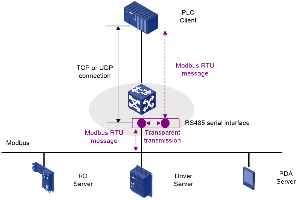
Typically, a Modbus client resides on the Ethernet network and sends Modbus-TCP messages. Modbus servers are connected via serial links and can identify only Modbus-RTU messages. As a result, the Modbus client cannot directly communicate with the Modbus servers. An H3C industrial switch acts as a relay gateway, enabling Modbus messages to be successfully exchanged between the client and servers, as shown in Figure 6.

Operating mechanism of the Modbus relay gateway
On a Modbus network, an H3C industrial switch physically connects to a Modbus client via an Ethernet interface and to Modbus servers via an RS485 serial interface. The switch must establish a TCP or UDP connection with the Modbus client so that the Ethernet TCP/IP network can carry Modbus messages. The switch also uses an RS485 serial interface to support the Modbus protocol. The RS485 serial interface enables the switch to establish a TCP or UDP connection and Ethernet communication with the Modbus client and serial communication with the Modbus servers.
An RS485 serial interface supports the following forwarding modes:
· Transparent mode—Typically, a Modbus client sends Modbus-TCP messages. However, a high-performance Modbus client can directly generate Modbus-RTU messages when it detects that a Modbus server supports only Modbus-RTU messages. The Modbus client then sends Modbus-RTU messages to the H3C industrial switch via the TCP/IP Ethernet path, as shown in Figure 7.
In transparent mode, an RS485 serial interface on the H3C industrial switch transparently transmits Modbus-RTU messages between the Modbus client and Modbus servers.
Figure 7 Transparent mode of the relay gateway
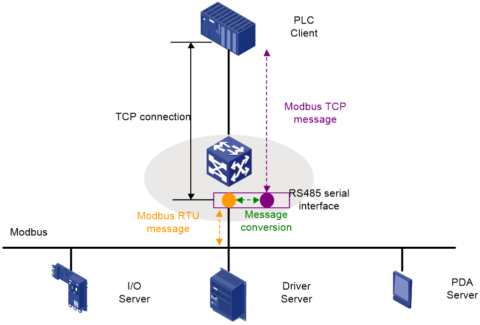
· Agent mode—An RS485 serial interface on the H3C industrial switch converts the Modbus-TCP messages received from a Modbus client to Modbus-RTU messages, and then forwards the converted messages to Modbus servers. The switch changes the Modbus-RTU messages received from a Modbus server to Modbus-TCP messages, and then forwards the converted messages to the Modbus client, as shown in Figure 8.
Figure 8 Agent mode of the relay gateway
The correspondence between the forwarding mode and the transport layer connection established for RS485 serial interfaces is as listed in Table 1.
|
Forwarding mode |
Transport layer connection to be established |
|
Transparent mode |
As Modbus-RTU messages have no requirements for the transport layer protocol on the Ethernet network, an RS485 serial interface can establish both TCP and UDP connections with the client. In addition, the RS485 serial interface can act as either the client or server during the establishment of TCP and UDP connections. |
|
Agent mode |
The Modbus-TCP protocol supports only TCP, so an RS485 serial interface must establish a TCP connection with the client, and must act as the TCP server. |
Modbus relay tasks at a glance
To configure Modbus relay, perform the following tasks:
1. Configuring operating parameters of an RS485 serial interface
2. Enabling Modbus and specifying the Modbus mode
3. Configure an RS485 serial interface to establish a TCP or UDP connection with the client
¡ Configuring an RS485 serial interface to establish a TCP connection with a Modbus client
¡ Configuring an RS485 serial interface to establish a UDP connection with a Modbus client
Only one type of connection can be configured for an RS485 serial interface. You can repeat the steps on multiple RS485 serial ports to establish multiple connections.
4. (Optional.) Optimizing Modbus performance
5. Restoring the default settings for an RS485 serial interface
Configuring operating parameters of an RS485 serial interface
About RS485 serial interfaces
An industrial switch acts as a relay device for Modbus protocol communication between the client and servers. The switch establishes a physical connection with a Modbus server via an RS485 serial interface. To ensure connectivity of RS485 links, make sure the parameters of the RS485 serial interface matches those for the industrial switch.
Procedure
1. Enter system view.
system-view
2. Enter RS485 serial interface view.
interface uart interface-number
3. Configure the description for the RS485 serial interface.
description text
By default, the description for an interface is interface name Interface (for example, UART1/0/1 Interface).
4. Configure the flow control mode.
flow-control none
By default, no flow control mode is configured for an RS485 serial interface.
5. Set the baud rate.
baudrate baudrate-value
By default, the baud rate is 9600 bps.
6. Specify the number of data bits
databits 8
By default, the number of data bits is 8.
7. Specify the number of stop bits.
stopbits { 1 | 2 }
By default, the number of stop bits for an RS485 serial interface is 1.
8. Specify the parity.
parity none
By default, the setting is none. No parity is used.
Enabling Modbus and specifying the Modbus mode
About this task
After you specify the forwarding mode for an RS485 serial interface, Modbus on this interface is enabled.
Restrictions and guidelines
You cannot edit the forwarding mode for an RS485 serial interface by repeating the modbus mode command. To edit the forwarding mode, execute the undo modbus mode command to remove the forwarding mode configuration, and then execute the modbus mode command to reconfigure the forwarding mode.
Executing the undo modbus mode command will restore the Modbus configuration to the factory defaults, which might cause a Modbus communication interruption.
Procedure
1. Enter system view.
system-view
2. Enter RS485 serial interface view.
interface uart interface-number
3. Enable Modbus and specify a forwarding mode for the RS485 serial interface and enter the corresponding Modbus mode view.
¡ Specify the agent mode for the RS485 serial interface and enter the Modbus agent mode view.
modbus mode agent
¡ Specify the transparent mode for the RS485 serial interface and enter the Modbus transparent mode view.
modbus mode raw
By default, no forwarding mode is specified for an RS485 serial interface. This indicates that the RS485 serial interface is disabled with Modbus and cannot process Modbus messages.
Configuring an RS485 serial interface to establish a TCP connection with a Modbus client
About this task
In agent mode, an H3C industrial switch acts as a Modbus server for a Modbus client and needs to receive Modbus-TCP messages from the client. Then, a TCP server connection is required. In transparent mode, an RS485 serial interface on an H3C industrial switch can act as a TCP server or TCP client to establish a TCP connection with a Modbus client for reliable transparent transmission of Modbus-RTU messages.
You can execute the modbus packet-size command to edit the minimum length of TCP packets that an RS485 serial interface sends to a Modbus client, accommodating various network environments. Increasing the minimum length enables multiple messages to be encapsulated into one TCP packet, which reduces system resource consumption caused by multiple packet encapsulations.
Restrictions and guidelines
You can configure this feature multiple times to configure an RS485 interface as a TCP client to establish TCP connections with a maximum of four Modbus clients. Do not specify TCP or UDP servers that have the same IP address for different RS485 serial interfaces on the device.
The tcp client, tcp server, udp client, and udp server commands are mutually exclusive. Do not execute two or more of these commands in the same view.
To ensure correct operation of Modbus and other services, specify an unused port number.
Configuring an RS485 serial interface as a TCP server to establish a TCP connection with a Modbus client
1. Enter system view.
system-view
2. Enter RS485 serial interface view.
interface uart interface-number
3. (Optional.) Set the minimum length of TCP packets that an RS485 serial interface sends to a Modbus client.
modbus packet-size size
By default, the minimum length of TCP packets that an RS485 serial interface sends to a Modbus client is not configured. The TCP packet length varies by actual data size.
4. Enter the Modbus transparent mode view or Modbus agent mode view.
modbus mode { agent | raw }
5. Configure an RS485 serial interface as a TCP server to establish a TCP connection with a Modbus client (TCP client).
tcp server [ server-port server-port ] [ vpn-instance vpn-instance-name ]
By default, no role is configured for an RS485 serial interface in establishing a transport layer connection. The interface does not establish any connection with a Modbus client at the transport layer.
Configuring an RS485 serial interface as a TCP client to establish a TCP connection with a Modbus client
1. Enter system view.
system-view
2. Enter RS485 serial interface view.
interface uart interface-number
3. (Optional.) Set the minimum length of TCP packets that an RS485 serial interface sends to a Modbus client.
modbus packet-size size
By default, the minimum length of TCP packets that an RS485 serial interface sends to a Modbus client is not configured. The TCP packet length varies by actual data size.
4. Enter the Modbus transparent view.
modbus mode raw
5. Configure an RS485 serial interface as a TCP client to establish a TCP connection with a Modbus client (TCP server).
tcp client server-ip server-ip server-port server-port [ vpn-instance vpn-instance-name ]
By default, no role is configured for an RS485 serial interface in establishing a transport layer connection. The interface does not establish any connection with a Modbus client at the transport layer.
Configuring an RS485 serial interface to establish a UDP connection with a Modbus client
About this task
The Modbus-TCP transmission mode depends on the TCP protocol. During the establishment of a UDP connection between an RS485 serial interface and a Modbus client, only transparent mode can be used to transmit Modbus-RTU messages. Establishing a UDP connection is efficient in message transmission.
Restrictions and guidelines
You can configure this feature multiple times to configure an RS485 serial interface to establish UDP connections with a maximum of four Modbus clients. Do not specify TCP or UDP servers that have the same IP addresses for different RS485 serial interfaces on the device.
The tcp client, tcp server, udp client, and udp server commands are mutually exclusive. Do not execute two or more of these commands in the same view.
To ensure correct operation of Modbus and other services, specify an unused port number.
Configuring an RS485 serial interface as a UDP server to establish a UDP connection with a Modbus client
1. Enter system view.
system-view
2. Enter RS485 serial interface view.
interface uart interface-number
3. Enter the Modbus transparent view.
modbus mode raw
4. Configure an RS485 serial interface as a UDP server to establish a UDP connection with a Modbus client (UDP client)
udp server [ server-port server-port ] [ vpn-instance vpn-instance-name ]
By default, no role is configured for an RS485 serial interface in establishing a transport layer connection. The interface does not establish any connection with a Modbus client at the transport layer.
Configuring an RS485 serial interface as a UDP client to establish a UDP connection with a Modbus client
1. Enter system view.
system-view
2. Enter RS485 serial interface view.
interface uart interface-number
3. Enter the Modbus transparent view.
modbus mode raw
4. Configure an RS485 serial interface as a UDP client to establish a UDP connection with a Modbus client (UDP server).
udp client server-ip server-ip server-port server-port [ local-port local-port ] [ vpn-instance vpn-instance-name ]
By default, no role is configured for an RS485 serial interface in establishing a transport layer connection. The interface does not establish any connection with a Modbus client at the transport layer.
Optimizing Modbus performance
Configuring minimum interval for an RS485 serial interface to send Modbus-RTU messages to a Modbus server
About this task
Modbus servers vary in type and their ability to process Modbus-RTU messages also differs. For low-performance Modbus servers, set a long Modbus-RTU message sending interval to avoid packet congestion. For high-performance Modbus servers, set a short Modbus-RTU message sending interval to accelerate the speed at which a Modbus client receives responses.
Procedure
1. Enter system view.
system-view
2. Enter RS485 serial interface view.
interface uart interface-number
3. Configure the minimum interval for the RS485 serial interface to send Modbus-RTU messages to a Modbus server.
modbus packet-time interval
By default, an RS485 serial interface sends Modbus-RTU messages to a Modbus server at least every 100 milliseconds.
Restoring the default settings for an RS485 serial interface
Restrictions and guidelines
|
|
CAUTION: The default command might interrupt ongoing network services. Make sure you are fully aware of the impact of this command when you use it on a live network. |
This feature might fail to restore the default settings for some commands because of command dependencies or system restrictions. You can use the display this command in interface view to identify these commands, and use their undo forms or follow the Modbus command reference to restore their default settings. If your restoration attempt still fails, follow the error message instructions to solve the problem.
Procedure
1. Enter system view.
system-view
2. Enter RS485 serial interface view.
interface uart interface-number
3. Restore the default settings for the RS485 serial interface.
default
Display and maintenance commands for Modbus relay
Execute display commands in any view.
|
Task |
Command |
|
Display information about RS485 serial interfaces. |
display interface [ uart [ interface-number ] ] [ brief [ description ] ] |
|
Display TCP sessions for an RS485 serial interface. |
display modbus session [ interface interface-type interface-number ] |
