- Table of Contents
- Related Documents
-
| Title | Size | Download |
|---|---|---|
| 01-Text | 14.07 MB |
Contents
General safety recommendations
Examining the installation site
Rack or workbench requirements
Installing the device in a standard 19-inch rack
Device dimensions and rack requirements
Installing the device on a workbench
4 Installing removable components
Installing a main-control and service-processing unit (MSU)
Install a SIC interface module
Install an XMIM interface module/SSD module
Connecting copper Ethernet cables
7 Accessing the device for the first time
Setting up the configuration environment
Connecting the device to a configuration terminal
8 Replacing removable components
Replace an XMIM interface module/SSD module
Replacing a SIC interface module
9 Hardware management and maintenance
Displaying software and hardware version information for the device
Displaying device operating information
Displaying detailed device information
Displaying electrical label information for the device
Displaying CPU usage information
Displaying memory usage information
Displaying the fan tray operating status
Displaying the power supply operating status
Displaying device temperature information
Displaying transceiver module information and diagnosing transceiver modules
Displaying transceiver module information
Diagnosing transceiver modules
Saving the running configuration
Rebooting the device or a module
Interface module, cable, and connection failure
System failure during operation
Guidelines for using the reset button
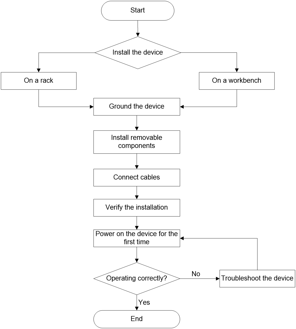
1 Device installation flow
The installation flow for the MSR5680-X3 router is as described in Figure1-1.
Figure1-1 Device installation flow
2 Preparing for installation
Safety recommendations
To avoid any equipment damage or bodily injury, read the following safety recommendations before installation. Note that the recommendations do not cover every possible hazardous condition.
General safety recommendations
· Do not place the device on an unstable case or desk. The device might be severely damaged in case of a fall.
· Keep the chassis clean and dust-free.
· Do not place the device on a moist area, and avoid liquid flowing into the device. Do not use wet cloth to wipe the device.
· Handle the devices according to the sizes of and packaging symbols on the packages.
Electrical safety
· Clear the work area of possible electricity hazards, such as ungrounded power extension cables, missing safety grounds, and wet floors.
· Locate the emergency power-off switch in the room before installation so you can quickly shut power off when an electrical accident occurs.
· Make sure the operating voltage is in the required range.
· Before powering on the device, make sure the device is reliably grounded.
Laser safety
|
|
WARNING! Disconnected optical fibers or transceiver modules might emit invisible laser light. Do not stare into beams or view directly with optical instruments when the device is operating. |
The device is a Class 1 laser device.
To avoid ESD damage, use dust caps on disconnected optical fiber connectors. Insert a dust plug into each fiber port and each transceiver module port not in use.
Moving safety
When you move the device, follow these guidelines:
· To avoid damage, move and unpack the device with care.
· After you move the device from a location below 0°C (32°F) to the equipment room, follow these guidelines to prevent condensation:
¡ Wait a minimum of 30 minutes before unpacking the device.
¡ Wait a minimum of 2 hours before powering on the device.
· Before you move the device, remove all cables.
· If the device is to be transported over a long distance, perform the following tasks before the transport:
¡ Remove all removable components, such as power supplies and interface cards, and place them separately in antistatic bags.
¡ Replace the filler panels provided with the device to prevent obstacle intrusions and damages to the device.
· To transport the device over a short distance, make sure the removable components are securely installed on the device and the screws are tightly fastened.
· When you move or lift the chassis, support the bottom of the chassis, rather than hold any removable component.
ESD prevention
|
|
CAUTION: Make sure the resistance reading between human body and the ground is in the range of 1 to 10 megohms (Mohms). |
No ESD wrist strap is provided with the device. Purchase one yourself.
Always wear an ESD wrist strap when installing removable components. Make sure the wrist strap is reliably grounded.
To attach the ESD wrist strap:
1. Wear the wrist strap on your wrist.
2. Lock the wrist strap tight around your wrist to keep good contact with the skin.
3. Secure the wrist strap lock and the alligator clip lock together.
4. Attach the alligator clip to the rack or the workbench.
Examining the installation site
The device can only be used indoors. To ensure correct operation and a long lifespan for your device, the installation site must meet the following requirements.
Temperature and humidity
Maintain appropriate temperature and humidity in the equipment room at levels as described in Table2-1.
· Lasting high relative humidity can cause poor insulation, electricity leakage, mechanical property change of materials, and metal corrosion.
· Lasting low relative humidity can cause washer contraction and ESD and bring problems including loose captive screws and circuit failure.
· High temperature can accelerate the aging of insulation materials and significantly lower the reliability and lifespan of the device.
Table2-1 Temperature and humidity requirements
|
Item |
Specification |
|
Temperature |
· Operating: 0°C to 45°C (32°F to 113°F) · Storage: –40°C to +70°C (–40°F to +158°F) |
|
Humidity |
· Operating: 5% RH to 95% RH, noncondensing · Storage: 5% RH to 95% RH, noncondensing |
Cleanliness
Dust buildup on the chassis might result in electrostatic adsorption, which causes poor contact of metal components and contact points, especially when indoor relative humidity is low. In the worst case, electrostatic adsorption can cause communication failure.
Table2-2 Router requirement for cleanliness
|
Substance |
Particle diameter |
Concentration limit |
|
Dust particles |
≥ 0.5 µm |
≤ 1.8 × 10⁷ particles/m3 |
Corrosive gases can accelerate corrosion and aging of metal components. Make sure the corrosive gases do not exceed the concentration limits as shown in Table2-3.
Table2-3 Corrosive gas concentration limits
|
Gas |
Average concentration (mg/m3) |
Maximum concentration (mg/m3) |
|
SO2 |
0.3 |
1.0 |
|
H2S |
0.1 |
0.5 |
|
Cl2 |
0.1 |
0.3 |
|
HCI |
0.1 |
0.5 |
|
HF |
0.01 |
0.03 |
|
NH3 |
1.0 |
3.0 |
|
O3 |
0.05 |
0.1 |
|
NOX |
0.5 |
1.0 |
Cooling system
For adequate cooling of the device, make sure the following requirements are met:
· A minimum clearance of 100 mm (3.94 in) is reserved around the inlet and outlet air vents.
· The installation site has a good cooling system.
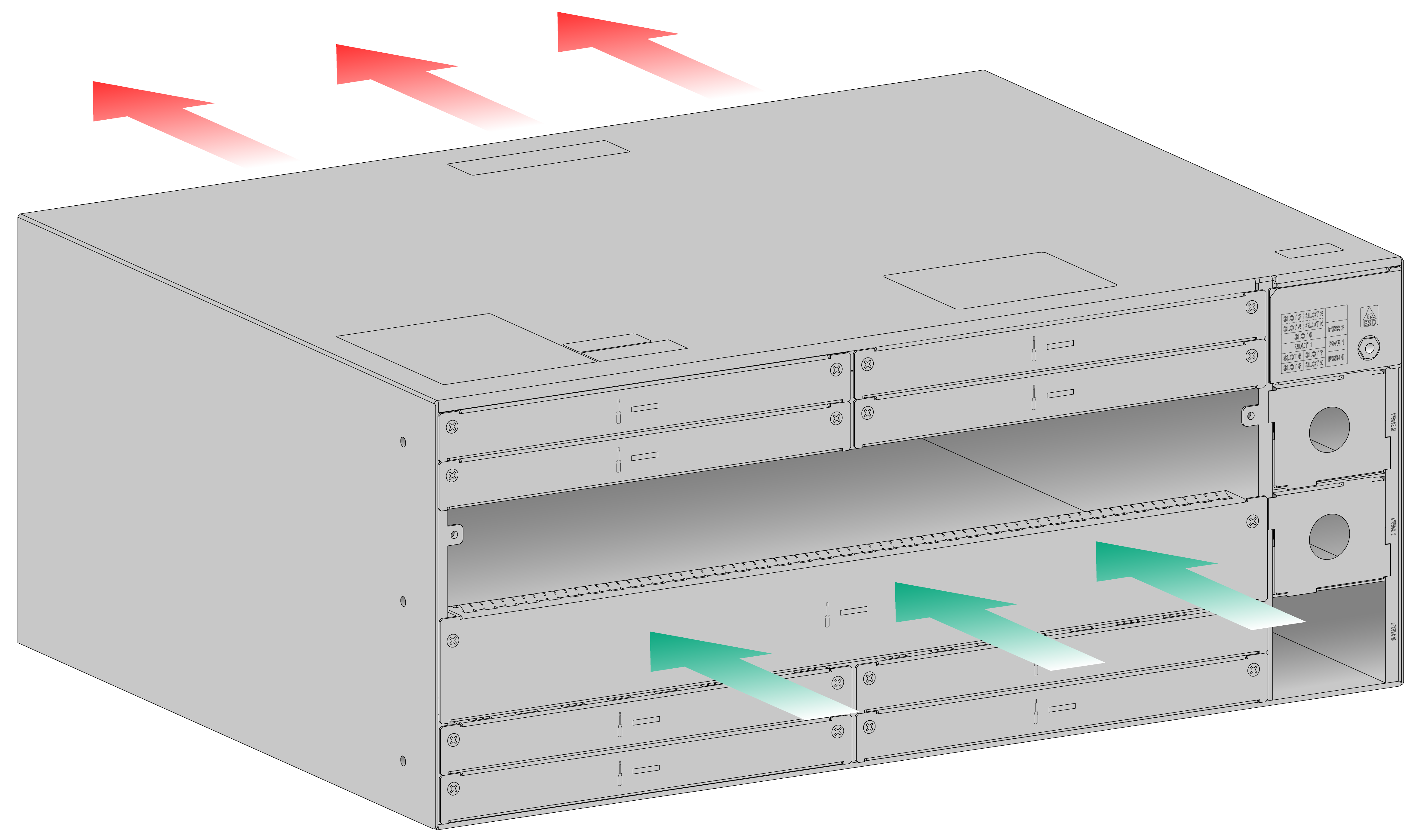
· Plan the cooling system at the installation site based on the airflow direction of the device.
· Verify the airflow directions of the devices above and below the device. Make sure the exhausted hot air of the lower device will not enter the upper device.
Figure2-1 Airflow through the chassis
Rack or workbench requirements
· Make sure the rack or workbench is sturdy enough to support the total weight of the device and its accessories. For more information about the device weight, see H3C MSR5680-X3 Router Hardware Information and Specifications.
· Make sure the dimensions of the rack or workbench meet the requirements.
· Make sure the rack or workbench is reliably grounded.
EMI
All electromagnetic interference (EMI) sources, from outside or inside of the device and application system, adversely affect the device in the following ways:
· A conduction pattern of capacitance coupling.
· Inductance coupling.
· Electromagnetic wave radiation.
· Common impedance (including the grounding system) coupling.
To prevent EMI, use the following guidelines:
· If AC power is used, use a single-phase three-wire power receptacle with protection earth (PE) to filter interference from the power grid.
· Keep the device far away from radio transmitting stations, radar stations, and high-frequency devices.
· Use electromagnetic shielding, for example, shielded interface cables, when necessary.
Lightning protection
To protect the device from lightning better, do as follows:
· Make sure the installation site, power supply system, and the device are reliably grounded.
· Install a lightning arrester at the input end of the power supply to enhance the lightning protection capability of the power supply.
· To prevent signal ports from getting damaged by overvoltage or overcurrent caused by lightning strikes, route interface cables only indoors. If part of the network cable of an Ethernet port must be routed outdoors, connect a lightning arrester to the cable before you plug the cable into the port.
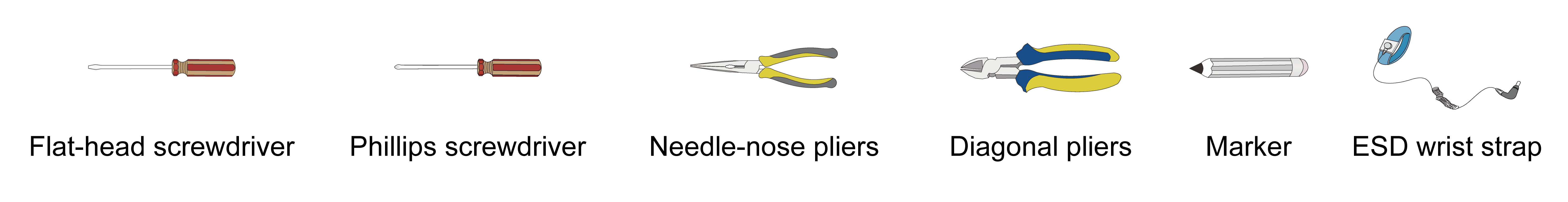
Installation tools
No installation tools are provided with the device. Prepare installation tools yourself as required.
Figure2-2 Installation tools
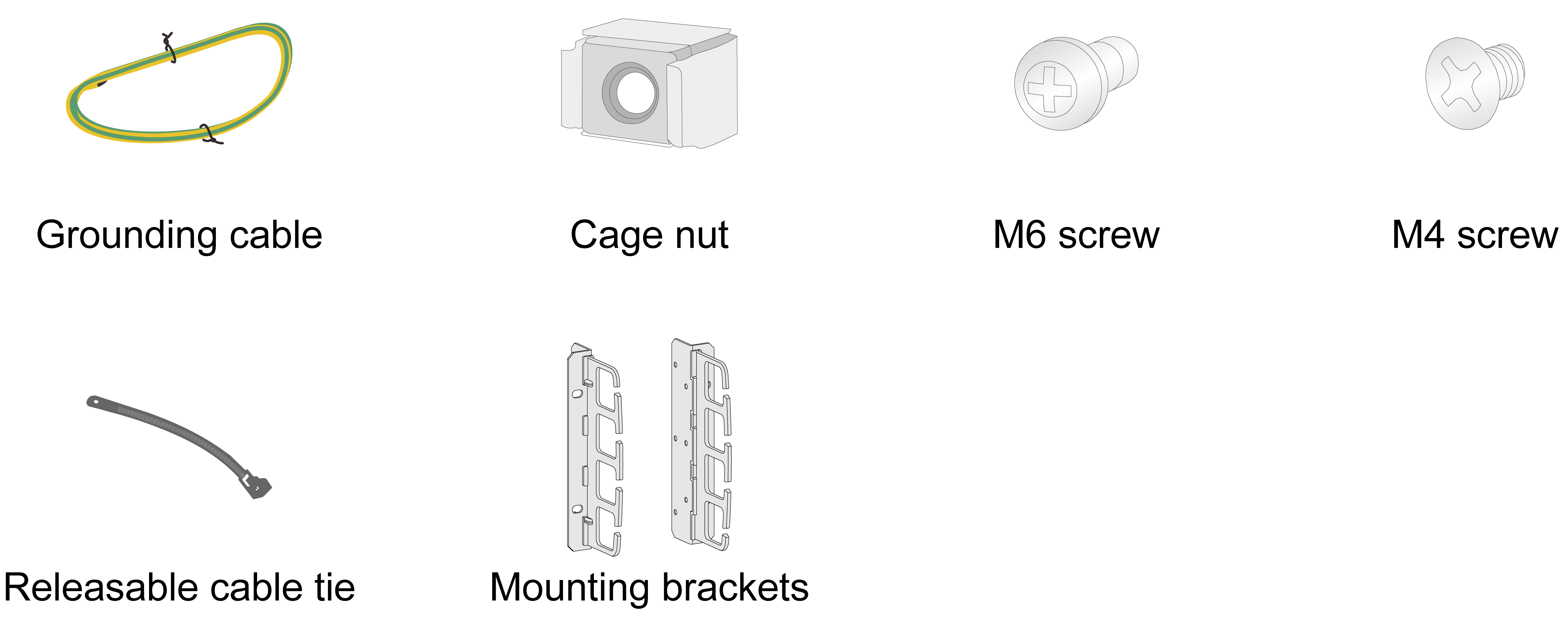
Installation accessories
Figure2-3 Installation accessories
3 Installing the device
Installing the device in a standard 19-inch rack
|
|
WARNING! To avoid bodily injury and device damage, a minimum of two persons are required to install the device. |
|
|
CAUTION: Ensure a clearance of 1 RU (44.45 mm, or 1.75 in) between the device and walls or other devices for heat dissipation. |
Device dimensions and rack requirements
To mount the device in a rack, make sure the rack meets the requirements described in Table3-1.
Table3-1 Device dimensions and rack requirements
|
Device dimensions |
Rack requirements |
|
· Height—175 mm (6.89 in) (4 RU) · Width—440 mm (17.32 in) · Total depth—420 mm (16.54 in) ¡ 330 mm (12.99 in) for the chassis ¡ 60 mm (2.36 in) for the AC/DC power cord at the chassis front ¡ 27 mm (1.06 in) for the fan tray handle at the chassis rear |
A minimum of 0.6 m (1.97 ft) in depth (recommended). · A minimum of 80 mm (3.15 in) between the front rack posts and the front door. · A minimum of 390 mm (15.35 in) between the front rack posts and the rear door. |
|
|
IMPORTANT: The router does not have rear mounting brackets. To mount it on a rack, use a tray. |
Rack-mounting the device
|
|
IMPORTANT: The device can achieve stable load bearing via mounting brackets. If a rack shelf is available in the equipment room, use mounting brackets together with the rack shelf for load distribution to further enhance load bearing performance. |
To install the device by using the mounting brackets and a rack shelf:
1. Wear an ESD wrist strap and make sure the strap makes good skin contact and is reliably grounded.
2. Identify the device installation position and secure the rack shelf to the rack.
3. Use the mounting brackets to mark the cage nut installation positions on the front rack posts according to the rack shelf position. Then, install cage nuts at the marked positions.
Figure3-1 Installing cage nuts
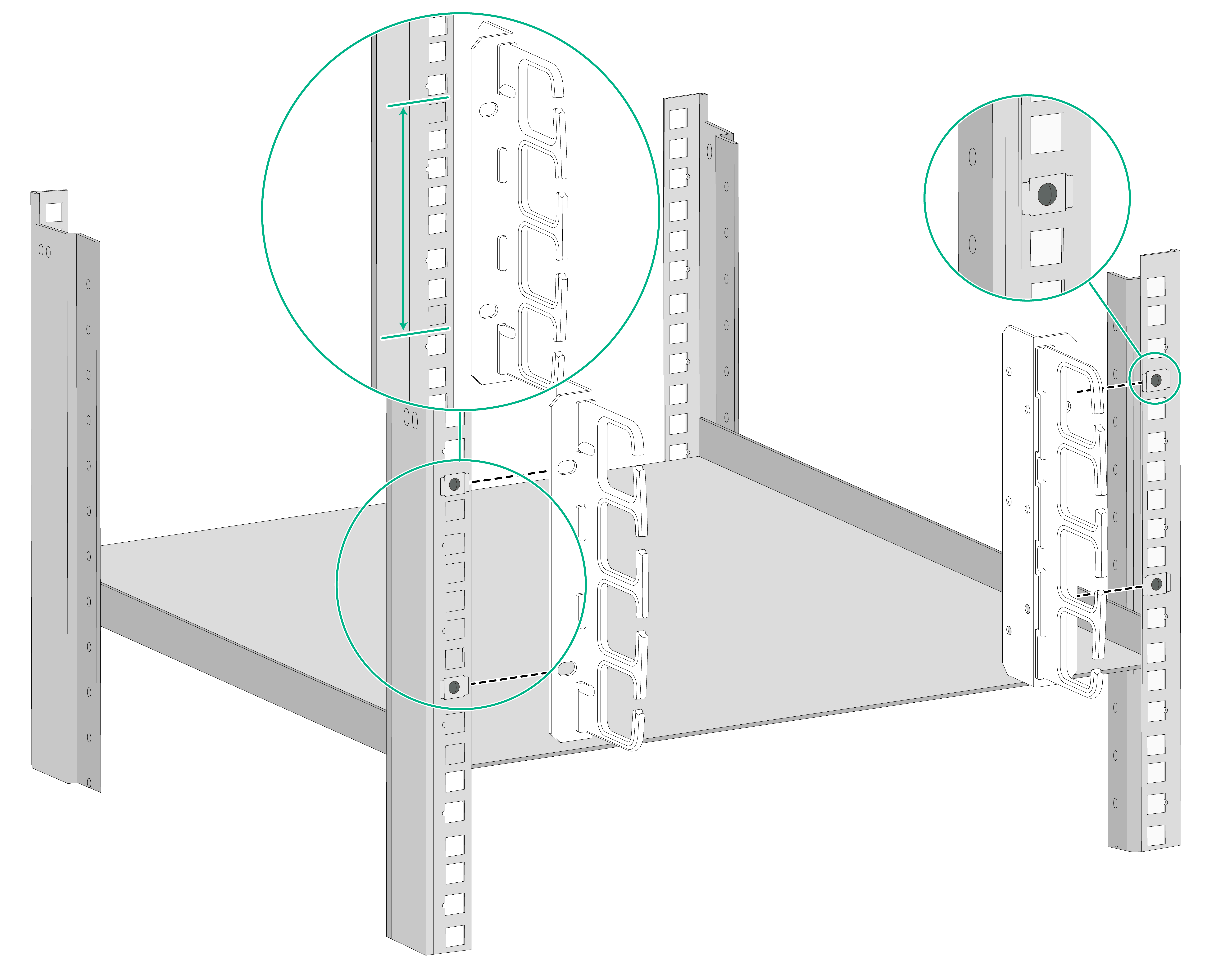
4. Use M4 mounting bracket screws to attach the mounting brackets to both sides of the device front panel.
Figure3-2 Attaching the mounting brackets to the device
5. Place the device horizontally on the rack shelf. Move the device along the rack shelf until the mounting brackets of the device are flush against the front the rack posts.
6. Use the M6 rack screws to secure the mounting brackets to the front rack posts.
Figure3-3 Mounting the device in the rack
Installing the device on a workbench
|
|
CAUTION: · Make sure the workbench is stable and reliably grounded. · Reserve a minimum clearance of 100 mm (3.94 in) around the chassis for heat dissipation. · Do not place heavy objects on the device. |
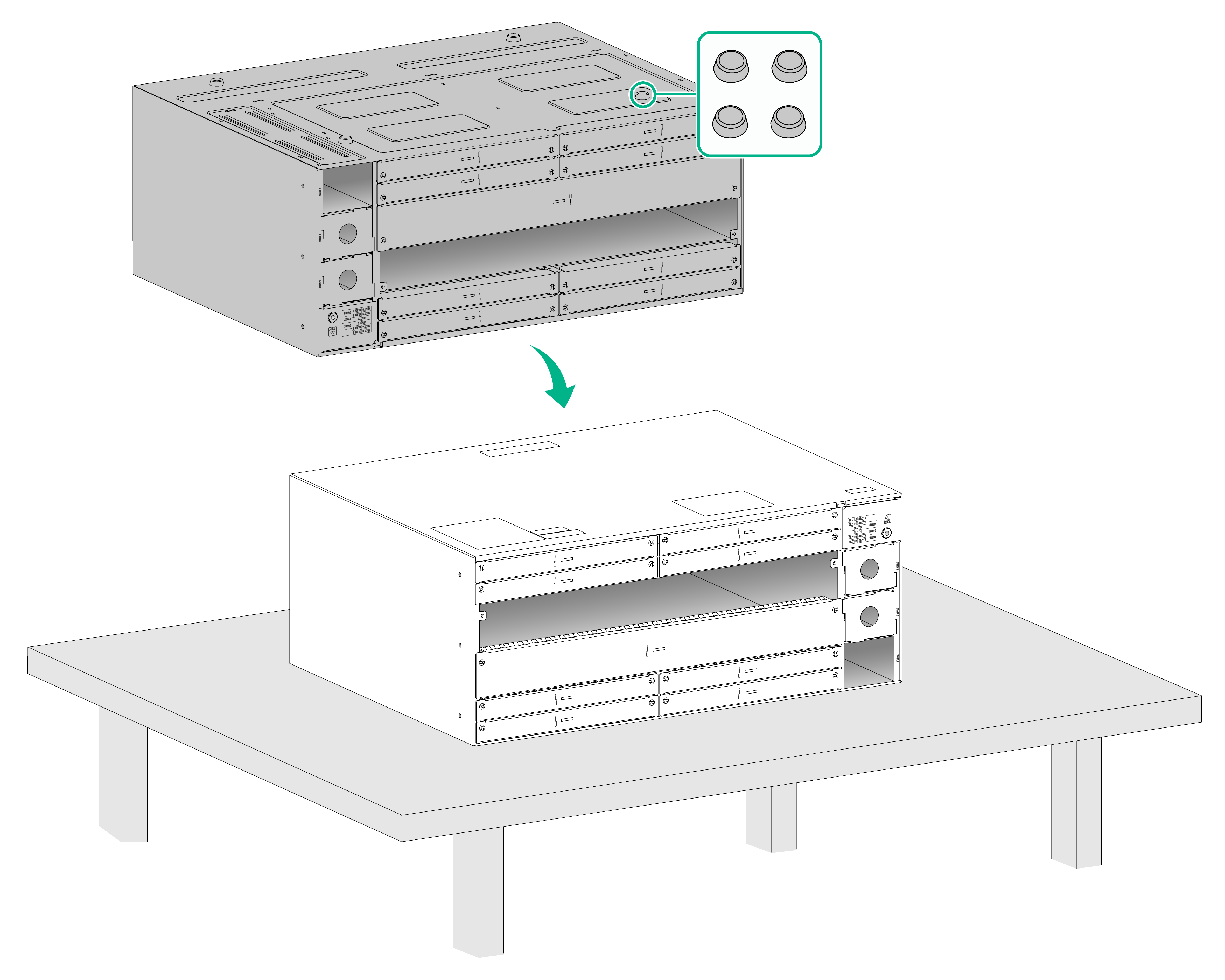
To install the device on a workbench:
1. Place the device upside down on the workbench and clean the four round holes in the chassis bottom with a dry cloth.
2. Attach the four rubber feet to the round holes in the chassis bottom.
3. Place the device with upside up on the workbench.
Figure3-4 Installing the device on a workbench
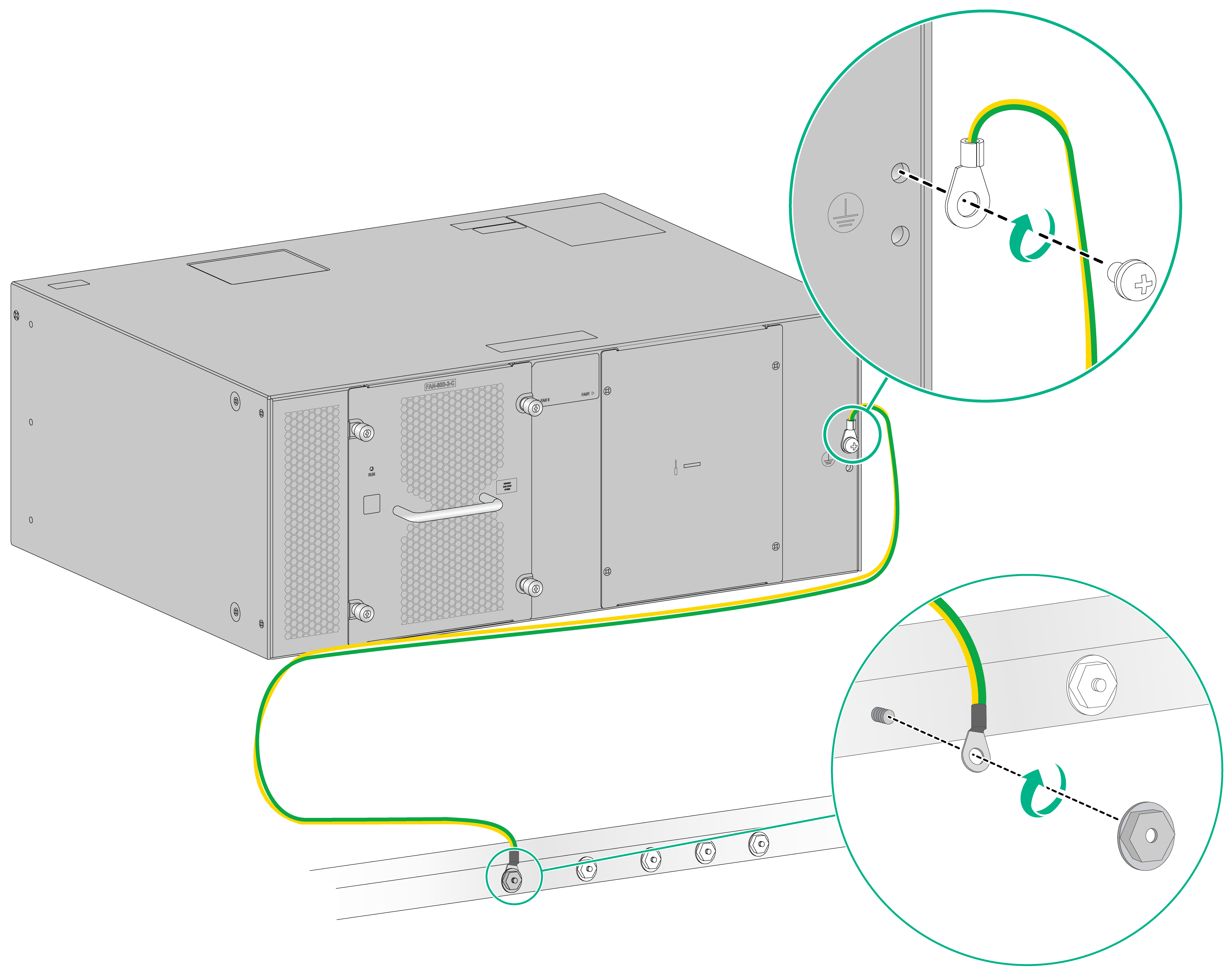
Grounding the device
|
|
WARNING! · Correctly connecting the grounding cable is crucial to lightning protection and EMI protection. · Do not connect the device grounding cable to a fire main or lightning rod. |
Grounding the device
To ground the device by using a grounding strip:
1. Use a Phillips screwdriver to remove the grounding screw from the device chassis.
2. Attach the grounding screw to the ring terminal of the grounding cable.
3. Use a Phillips screwdriver to fasten the grounding screw into the grounding hole on the device.
4. Connect the other end (ring terminal) of the grounding cable to a grounding strip or a grounding point on the rack.
Figure3-5 Grounding the device
4 Installing removable components
|
|
CAUTION: · Make sure each slot has a module or a filler panel installed while the device is operating. · Keep the packaging boxes and bags for the filler panels and removable components secure for future use. · To avoid device damage, do not hold the power supply handle or ejector levers on a module to move the device. |
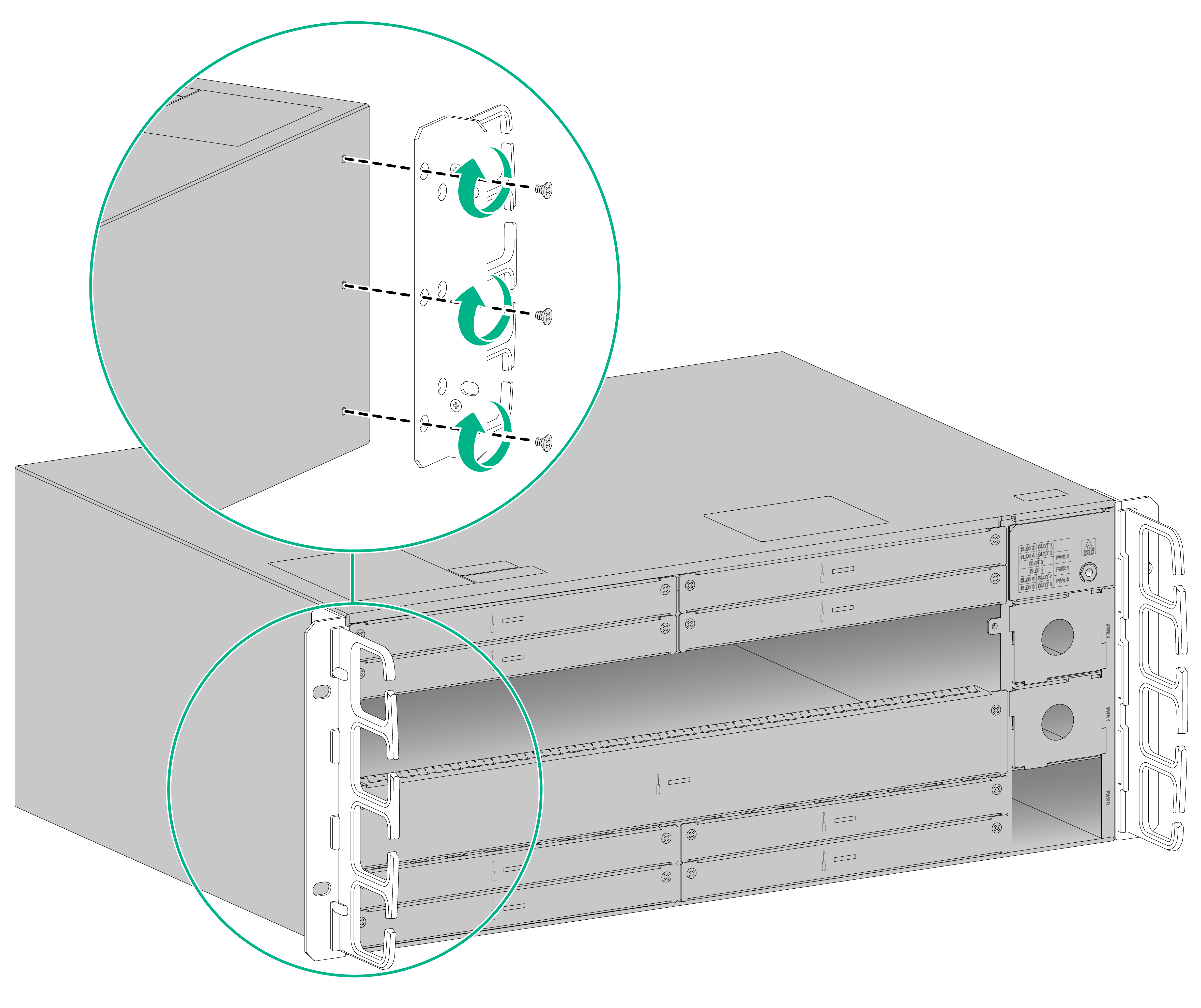
Installing a main-control and service-processing unit (MSU)
|
|
CAUTION: · Active/standby MSU switchover is supported when the device is configured with two MSUs. For the standby MSU to operate correctly, make sure it is the same model as the active MSU. · MSUs can be hot swapped. To hot swap an MSU with a storage medium, first execute the umount command to unmount the file system. Remove the MSU only after the system prompts that the file system is unmounted successfully. · To ensure smooth insertion when you install two adjacent MSUs vertically, press down the ejector levers on the latter MSU before pushing it into the slot slowly. |
To install an MSU:
1. Put on an ESD wrist strap. Make sure the wrist strap makes good skin contact and is reliably grounded.
2. If the ejector levers on the MSU have locking clips, hold the ejector levers with both hands, press the locking clips with your thumbs, and then pull outward the ejector levers. Skip this step if the ejector levers on the MSU do not have locking clips.
3. Push the MSU gently into the slot along the guide rails, and then close the ejector levers.
4. Use a Phillips screwdriver to fasten the two captive screws on the MSU to secure the MSU to the device.
Figure4-1 Installing an MSU (with ejector levers that do not have locking clips)
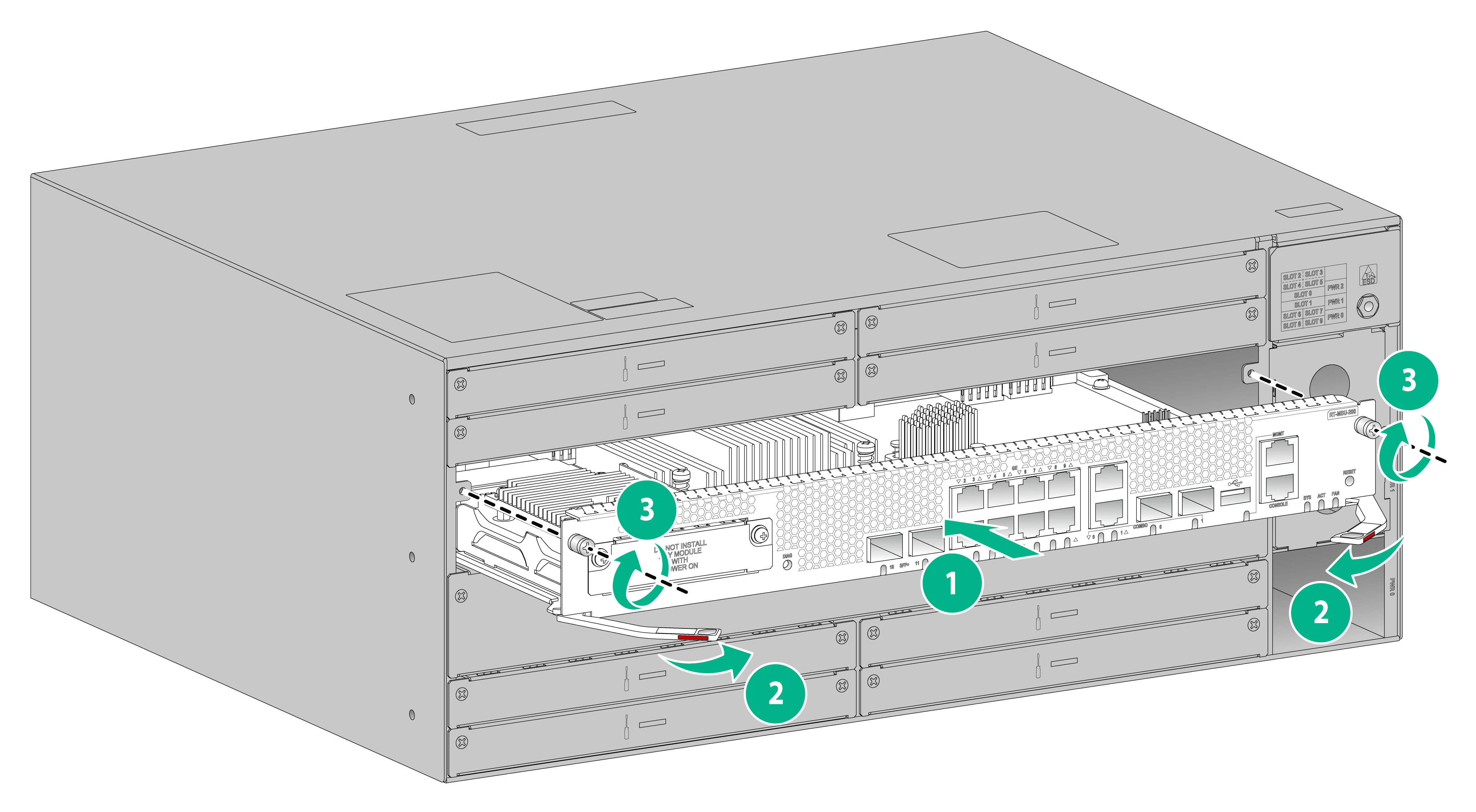
Figure4-2 Installing an MSU (with ejector levers that have locking clips)
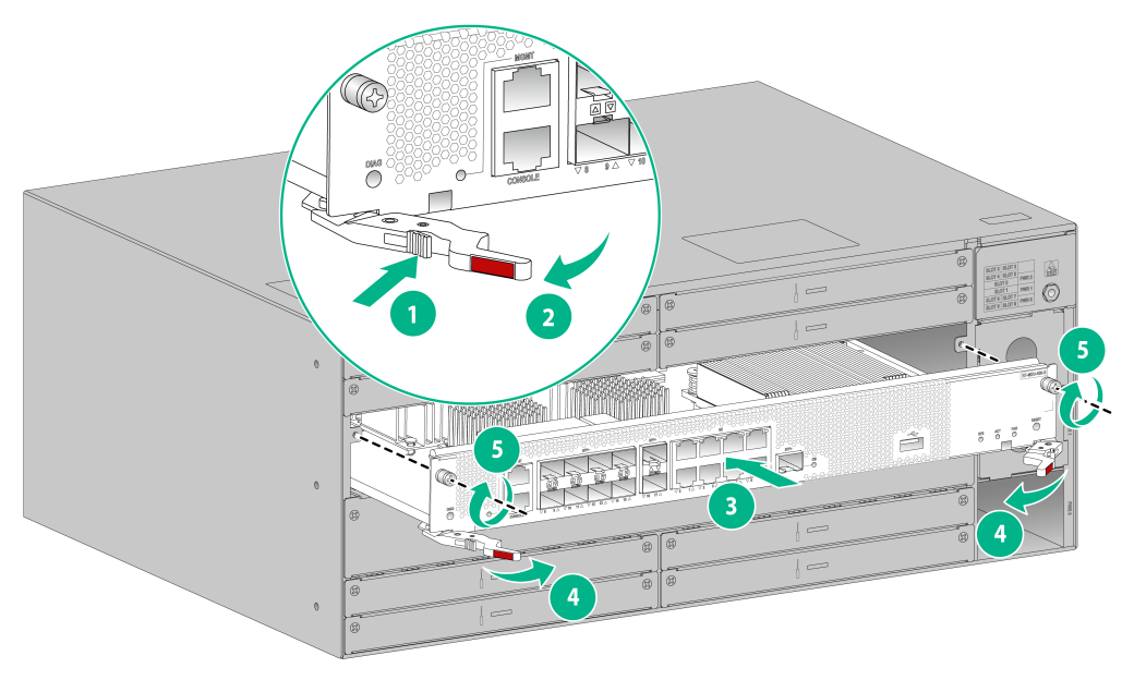
Install a SIC interface module
The device supports installing SIC interface modules only when it is installed with MSU-200s.
SIC interface modules can be hot swapped. To remove a SIC interface module while the device is operating, execute the remove command or press and hold the remove button for more than 3 seconds until the remove LED is off.
To install a SIC interface module:
1. Use a Phillips screwdriver to remove the fastening screws on the filler panel and then remove the filler panel.
2. Push the module slowly into the slot along the guide rails until it is seated securely in the slot.
3. Fasten the captive screws to secure the module to the device.
Figure4-3 Install a SIC interface module
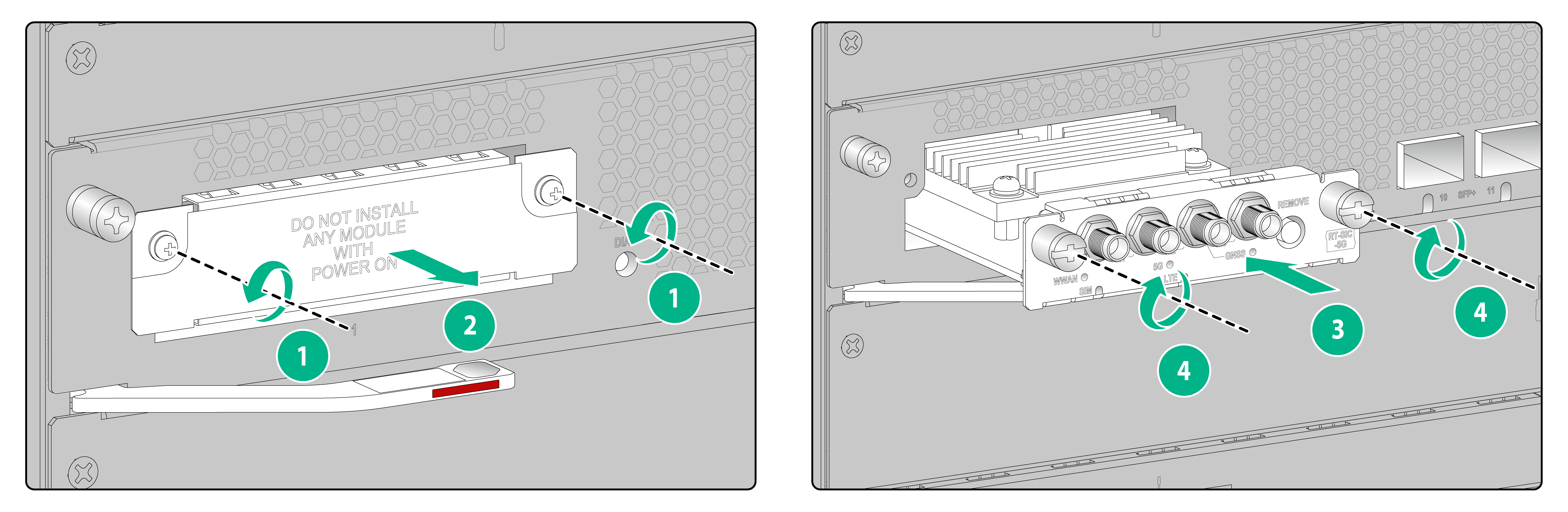
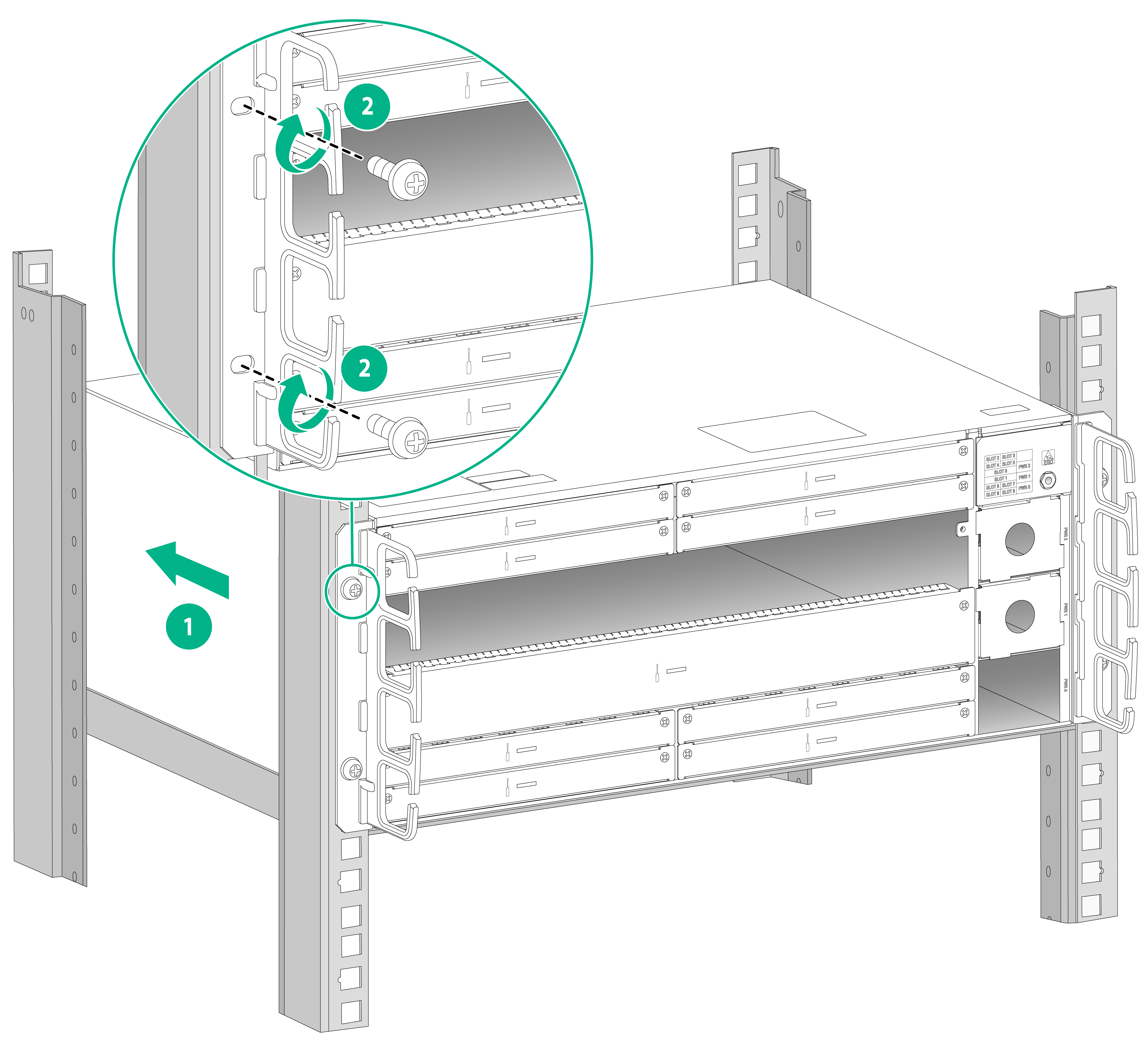
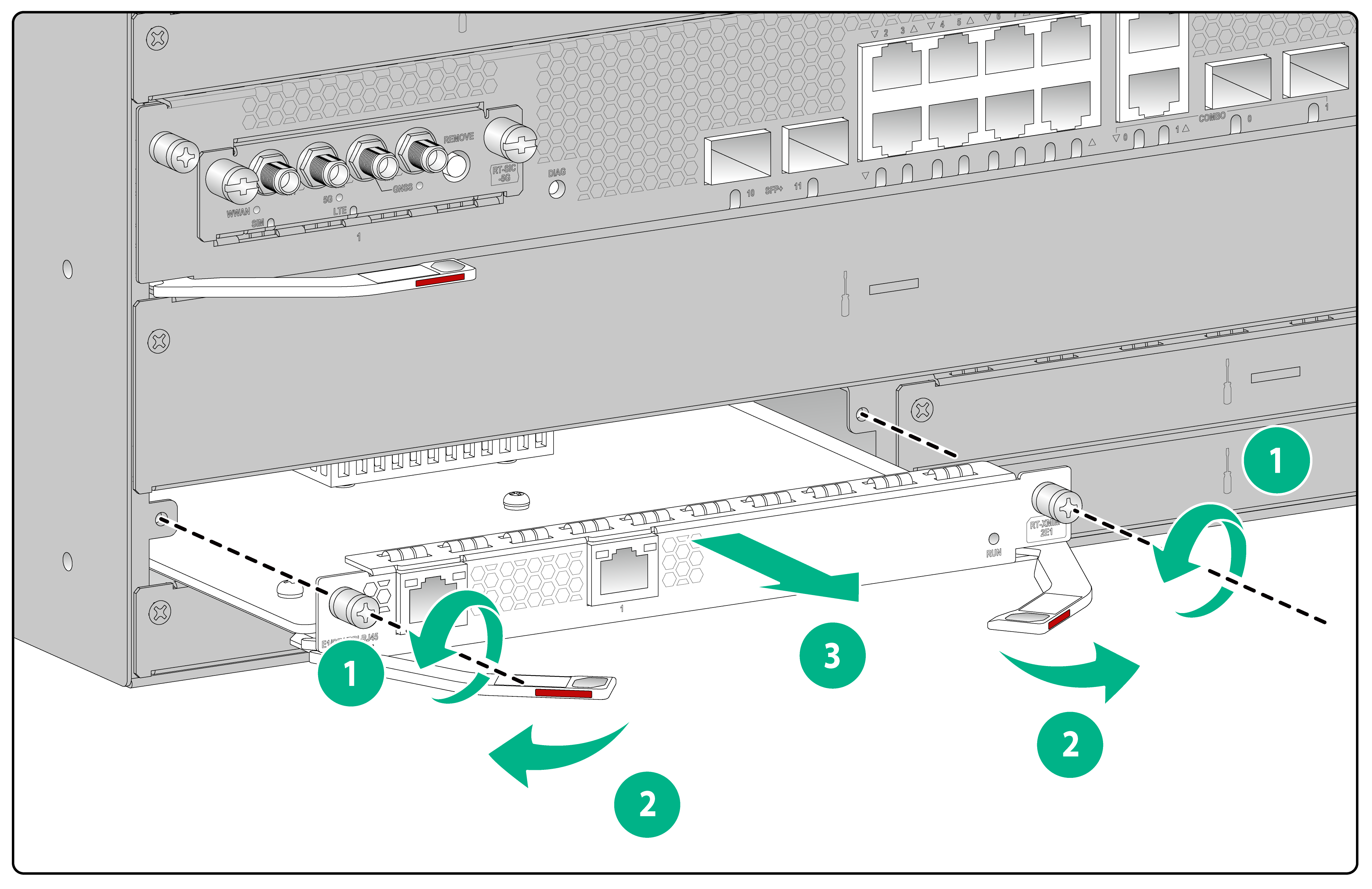
Install an XMIM interface module/SSD module
|
|
CAUTION: · XMIM interface modules can be hot swapped, with the exception of those with a remove button. To remove an XMIM interface module with a remove button while the device is operating, first press and hold the remove button until the RUN LED is off. For more information about hot swapping of interface modules, see H3C MSR Router Series Interface Module Guide. · SSD modules can be hot swapped. To remove an SSD module while the device is operating, first press and hold the remove button until the RUN LED is off. For more information about hot swapping of SSD modules, see H3C MSR Router Series Interface Module Guide. · Do not install an XMIM interface module or SSD module during an active/standby MSU switchover. To view the MSU status, execute the display system stable state command in any view. · To ensure smooth insertion when you install two adjacent XMIM interface modules or SSD modules vertically, press down the ejector levers on the latter XMIM interface module or SSD module before pushing it into the slot slowly. |
The installation procedure is the same for XMIM interface modules and SSD modules. The following uses an XMIM interface module as an example.
To install an XMIM interface module:
1. Put on an ESD wrist strap. Make sure the wrist strap makes good skin contact and is reliably grounded.
2. Use a Phillips screwdriver to remove the fastening screws on the filler panel. Then, feed the tip of a flat-head screwdriver through the hole on the filler panel, and pull the filler panel outwards to remove the filler panel. Keep the removed filler panel secure.
3. Pull outward the two ejector levers of the module and then push the module slowly into the slot along the guide rails.
4. Push inward the two ejector levers to ensure that the interface module is firmly seated in the slot.
5. Use a Phillips screwdriver to fasten the captive screws on the interface module.
Figure4-4 Install a XMIM interface module
Installing a fan tray
|
|
CAUTION: · Fan trays can be hot swapped. · To ensure adequate heat dissipation, make sure each fan tray slot has a fan tray present. To use only one fan tray for the device, install it in slot 0. · The device comes with a fan tray installed. To add a fan tray, recalculate the system power consumption and prepare enough power supplies. |
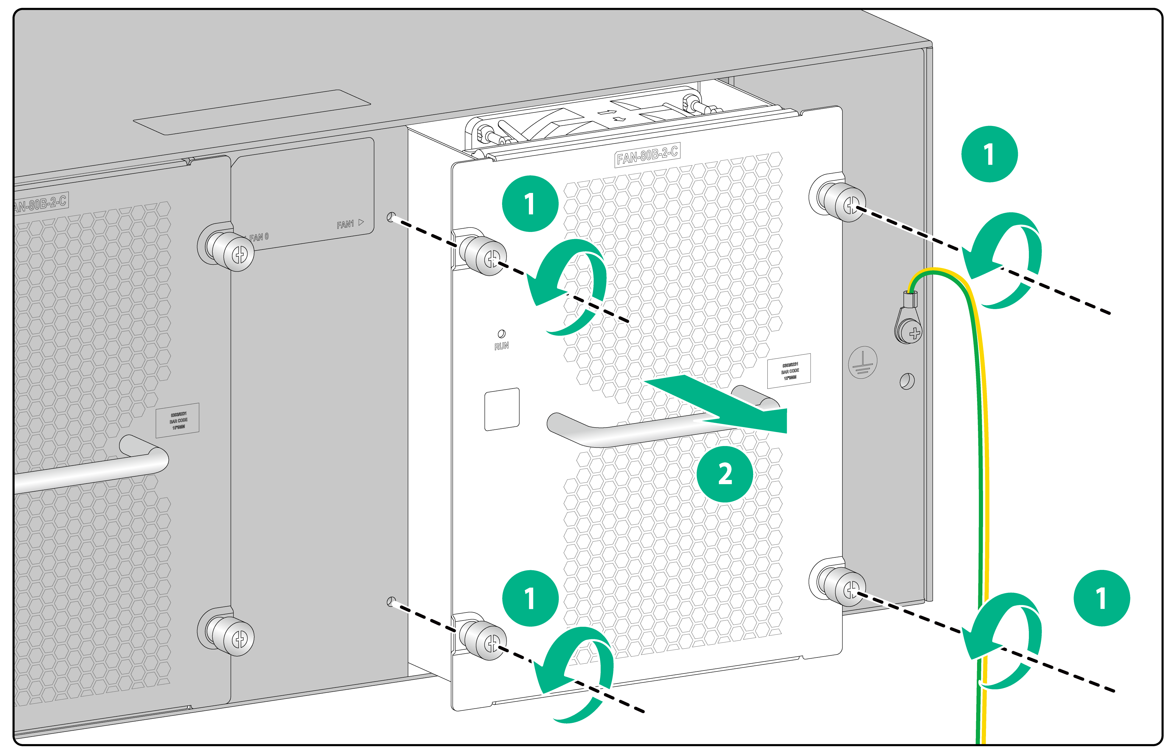
To install a fan tray:
1. Put on an ESD wrist strap. Make sure the wrist strap makes good skin contact and is reliably grounded.
2. Use a Phillips screwdriver to remove the fastening screws on the fan tray and then remove the filler panel. Keep the removed filler panel secure.
3. Holding the handle of the fan tray with one hand and supporting its bottom with the other, gently insert the fan tray into the fan tray slot along the guide rails until the fan tray is fully seated in the slot.
4. Use a Phillips screwdriver to fasten the captive screws on the fan tray.
Figure4-5 Installing a fan tray

Installing a power supply
|
|
WARNING! Provide a separate circuit breaker for each power supply. |
|
|
CAUTION: · The device supports only mix of 450 W AC and DC power supplies. · Do not install AC and DC power supplies on the same device. · To prevent damage to the connectors inside the chassis, insert the power supply gently. If you encounter a hard resistance while inserting the power supply, pull out the power supply and insert it again. |
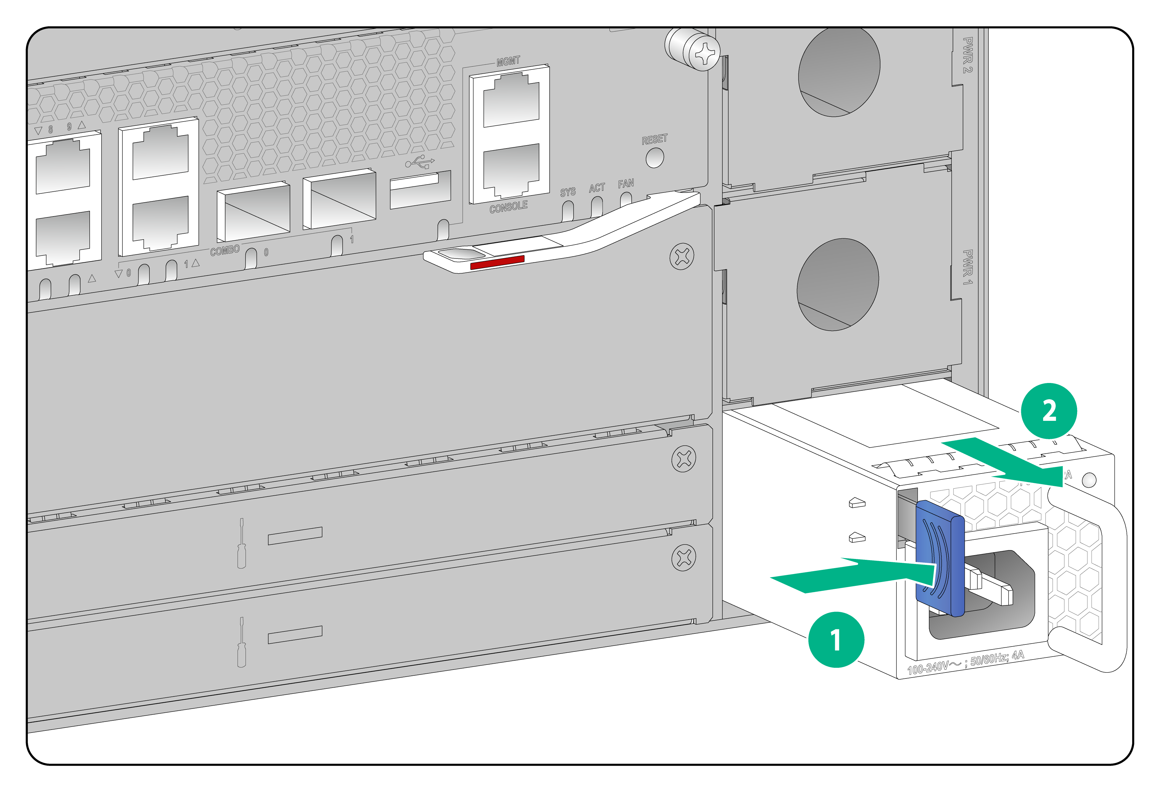
To avoid device damage or bodily injury, install a power supply as shown in Figure4-6.
Figure4-6 Installation procedure
![]()
The installation procedure is similar for AC and DC power supplies. This following procedure installs an AC power supply.
To install a power supply:
1. Wear an ESD wrist strap and make sure the strap makes good skin contact and is reliably grounded.
2. Remove the filler panel, if any, from the target power supply slot.
Figure4-7 Removing the filler panel from a power supply slot

3. Unpack the power supply and verify that the power supply model is correct.
4. Correctly orient the power supply with the power supply slot. Grasp the handle of the power supply with one hand and support its bottom with the other, and slide the power supply slowly along the guide rails into the slot.
The slot is foolproof. If you cannot insert the power supply into the slot, re-orient the power supply rather than use excessive force to push it in.
Figure4-8 Installing a power supply

5 Connecting cords
|
|
CAUTION: · Before connecting a power cord, make sure the device is reliably grounded. · Use a separate circuit breaker for each power input. Before connecting a power cord, turn off the circuit breaker for the power input. · Each power supply is provided with a power cord. Use this power cord other than other power cords to connect the power supply to a power source. |
Connecting power cords
Connecting an AC power cord
1. Wear an ESD wrist strap. Make sure the wrist strap makes good skin contact and is reliably grounded.
2. Insert the female connector of the power cord into the AC power receptacle on the power supply.
3. Use a cable tie to secure the power cord to the handle of the power supply.
4. Connect the other end of the power cord to an AC power source.
Figure5-1 Connecting an AC power cord
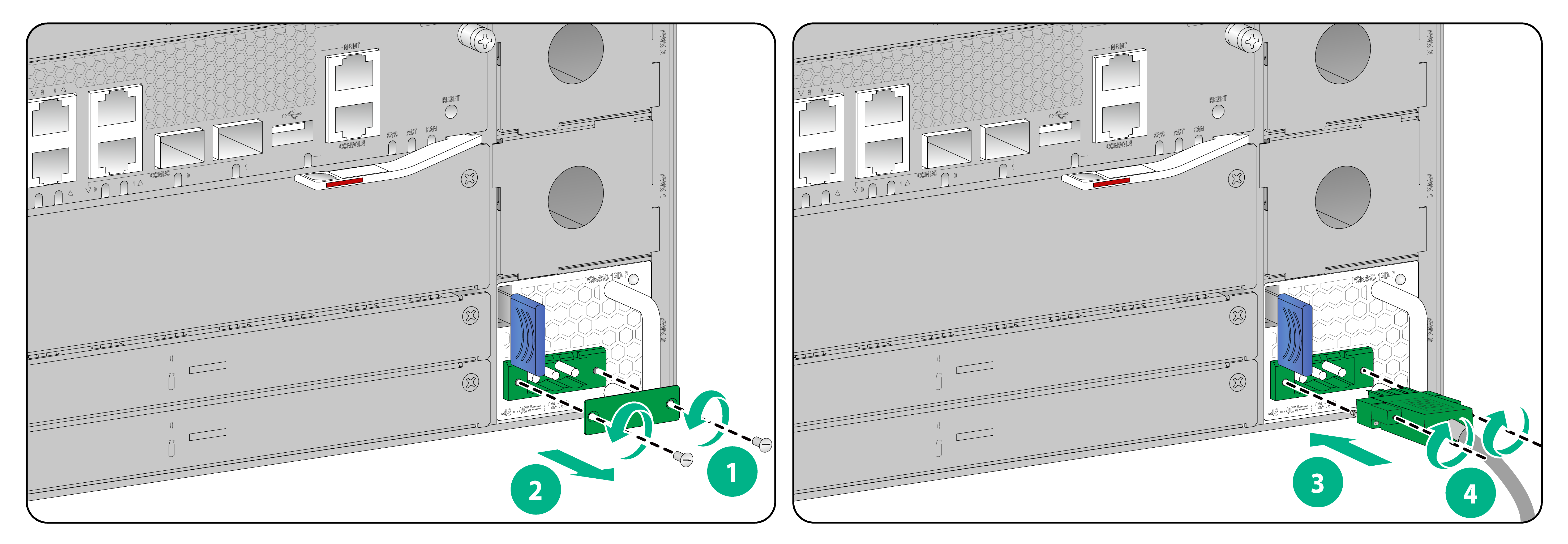
Connecting a DC power cord
1. Wear an ESD wrist strap. Make sure the wrist strap makes good skin contact and is reliably grounded.
2. Use a flat-head screwdriver to loosen the screws on the protective plate over the DC power receptacle and then remove the plate.
3. Correctly orient the DC power cord connector and insert it into the power receptacle.
The DC power cord connector and DC power receptacle form an anti-misinsertion structure. If you orient the DC power cord connector upside down, you cannot insert it into the receptacle.
4. Use a flat-head screwdriver to fasten the screws on the power cord connector to secure the connector to the power receptacle.
5. Connect the other end of the DC power cord to the wiring terminals of a DC power source, with the negative wire (–) to the negative terminal (–) and the positive wire (+) to the positive terminal (+).
Figure5-2 Connecting a DC power cord
Connecting copper Ethernet cables
Auto-MDI/MDIX is supported on the Ethernet copper ports on the front panel of the device and the 10/100/1000BASE-T ports on the interface cards. You can use straight-through or cross-over network cables to connect the copper Ethernet ports.
To connect a copper Ethernet cable:
1. Connect one end of the Ethernet cable to a copper Ethernet port on the device, and the other end of the cable to the peer Ethernet port.
2. Examine the LED for the Ethernet port to verify that the port is operating correctly. For more information about the LEDs, see H3C MSR5680-X3 Router Hardware Information and Specifications.
|
|
NOTE: After connecting the device to the network, you can use the ping or tracert command to verify network connectivity of the device. For more information about the commands, see the command references for the device. |
Connecting optical fibers
|
|
WARNING! Disconnected optical fibers or transceiver modules might emit invisible laser light. Do not stare into beams or view directly with optical instruments when the device is operating. |
|
|
CAUTION: · Never bend an optical fiber excessively. The bend radius of an optical fiber must be not less than 100 mm (3.94 in). · Keep the fiber end clean. · To connect an optical fiber to a fiber port, make sure the fiber connector matches the transceiver module. · Before connecting an optical fiber, make sure the received optical power does not exceed the upper receive power threshold of the transceiver module. If the threshold is exceeded, the transceiver module might be damaged. · To connect an optical fiber to a fiber port, first install a transceiver module in the fiber port and then connect the optical fiber to the transceiver module. · Insert a dust plug into any open fiber port. |
To connect an optical fiber:
1. Remove the dust plug from the fiber port.
2. Pivot the clasp of the transceiver module up to catch the clip on the top. Hold the two sides of the transceiver module and insert it slowly into the fiber port.
3. Remove the dust cap from the optical fiber connector, and use dust-free paper and absolute ethanol to clean the end face of the fiber connector.
4. Identify the Rx and Tx ports on the transceiver module. Use the optical fiber to connect the Rx port and the Tx port on the transceiver module to the Tx port and the Rx port on the peer device, respectively.
Figure5-3 Connecting a transceiver module and optical fiber

6 Verifying the installation
After the installation is completed, verify the following items:
· There is enough space around the device for heat dissipation.
· The rack or workbench is stable.
· The grounding cable is correctly and securely connected.
· The power supplies are compatible with the device, and the power source is as required by the device.
· The power cords are correctly connected.
· If part of the network cable for a port is routed outdoors, verify that a network port lightning protector is used for the port.
· If a power line is routed from outdoors, verify that a surge protected power strip is used for the device.
7 Accessing the device for the first time
To access the device for the first time, use a console cable to connect a console terminal (for example, a PC) to the serial console port on the device.
Setting up the configuration environment
Use a console cable to connect the configuration terminal (such as a PC) to the console port on the device.
Connecting the device to a configuration terminal
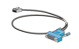
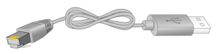
Console cables
As shown in Table7-1, two types of console cables can be used for connecting a configuration terminal to the console port on the device. No console cable is provided with the device. Purchase a console cable as required.
Table7-1 Console cables for connecting the console port
|
Console cable type |
Console cable view |
Router-side connector |
Configuration terminal-side connector |
|
DB9-to-RJ45 console cable |
|
DB-9 female connector |
RJ-45 |
|
USB-to-RJ45 console cable |
|
USB |
RJ-45 |
Connecting a DB9-to-RJ45 console cable
|
|
CAUTION: The serial ports on PCs do not support hot swapping. If the device has been powered on, connect the serial console cable to the PC before connecting to the device, and when you disconnect the cable, first disconnect from the device. |
To connect the device to a configuration terminal by using a serial console cable:
1. Connect the DB-9 female connector of the console cable to the serial port on the configuration terminal.
2. Connect the RJ-45 connector to the console port on the device.
Connecting a USB-to-RJ45 console cable
|
|
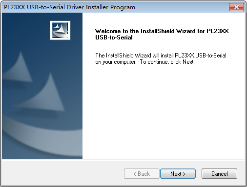
IMPORTANT: · To use a USB-to-RJ45 console cable to connect the router to a configuration terminal, first download and install the USB-to-RJ45 console driver on the configuration terminal, and then connect the USB-to-RJ45 console cable to the configuration terminal. To download the USB-to-RJ45 console driver, access the H3C official website or scan the QR code on the cable package. · If you have connected a USB-to-RJ45 console cable to the configuration terminal before installing the driver, remove and reconnect the USB-to-RJ45 console cable to the configuration terminal after driver installation. |
The following installs the driver on the Windows system. To install the driver on other operating systems, see the installation guide in the driver compression package named by using the corresponding operating system.
To connect the router to a configuration terminal by using a USB-to-RJ45 console cable:
1. Click the following link, or copy it to the address bar on your browser and download the USB-to-RJ45 console driver.
http://www.h3c.com/en/home/USB_to_RJ45_Console/
2. View the TXT file Read me in the Windows folder to check whether the Windows system of the configuration terminal supports the driver.
3. If the Windows system supports the driver, install PL23XX-M_LogoDriver_Setup_v200_20190815.exe.
4. Click Next on the welcome page of the driver installation wizard.
Figure7-1 Driver installation wizard
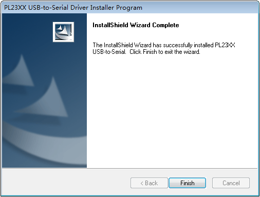
5. Click Finish after the drive installation is completed.
Figure7-2 Finishing the driver installation
6. Connect the standard USB connector of the cable to the USB port of the configuration terminal.
7. Connect the RJ-45 connector of the cable to the console port of the router.
Setting terminal parameters
To configure and manage the device through the console port, you must run a terminal emulator program, HyperTerminal or PuTTY, on your configuration terminal. You can use the emulator program to connect a network device, a Telnet site, or an SSH site. For more information about the terminal emulator programs, see the user guides for these programs
Configure the terminal parameters as follows:
· Bits per second—9600.
· Data bits—8.
· Stop bits—1.
· Parity—None.
· Flow control—None.
Starting the device
1. Verify that the following conditions are met before powering on the device:
¡ The power cord is correctly connected.
¡ The input power voltage is as required by the device.
¡ The console cable is correctly connected.
¡ The configuration terminal (a PC, for example) has started, and terminal parameters have been configured correctly.
2. Power on the device.
After powering on the device, you can determine whether the device is operating correctly by observing the system status LED (SYS) on the device. If the SYS LED is flashing green at 1 Hz, the device is operating correctly.
During the startup process, you can access Boot ROM menus to perform tasks such as software upgrade and file management. The Boot ROM interface and menu options vary by software version. For more information about Boot ROM menu options, see the release notes for the specific software version.
3. Examine the LEDs on the device to verify that the device is operating correctly. If the RUN LED is flashing green at 1 Hz, the device is operating correctly. For more information about the LEDs, see H3C MSR5680-X3 Router Hardware Information and Specifications.
4. Access the CLI to configure the device.
For more information about the configuration commands, see the configuration guides and command references for the device.
8 Replacing removable components
Replacing a power supply
|
|
WARNING! To avoid device damage or bodily injury, strictly follow the removal procedure in Figure8-1 to remove a power supply. |
Figure8-1 Power supply removal procedure
![]()
|
|
CAUTION: For adequate heat dissipation and dust prevention, install a filler panel in a power supply slot if you are not to install a new power supply in the slot after removing the old one. |
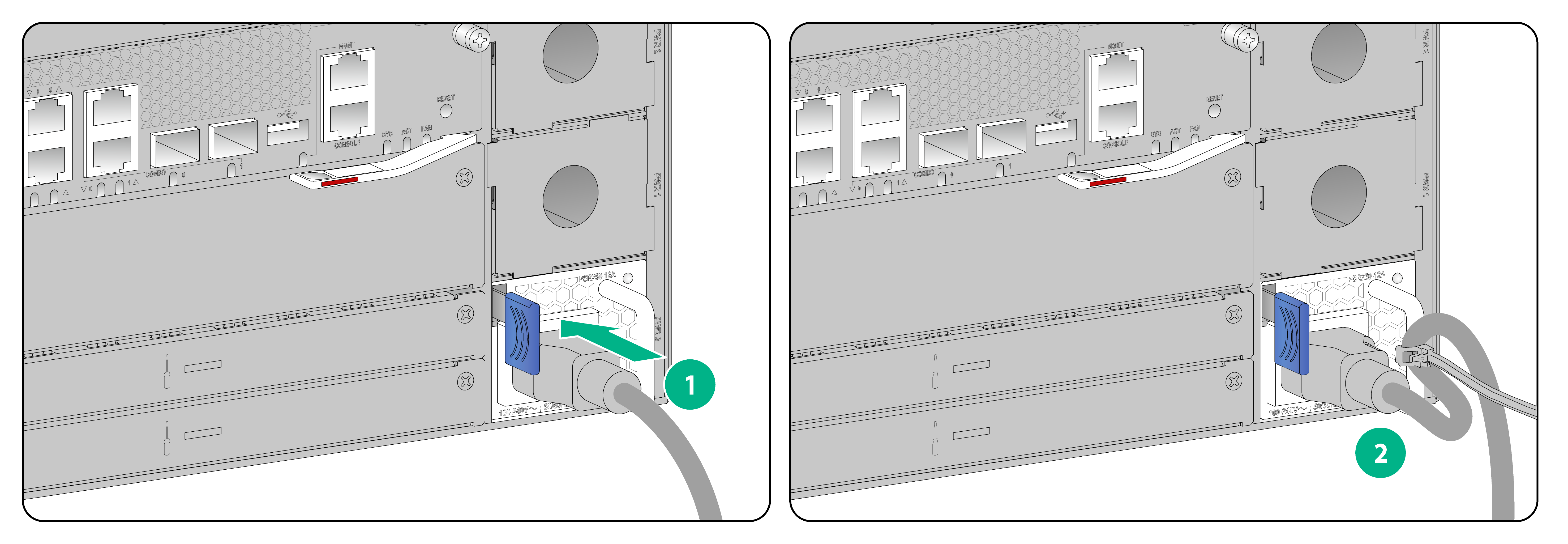
1. Wear an ESD wrist strap. Make sure the wrist strap makes good skin contact and is reliably grounded.
2. Remove the power cord from the power supply.
3. Pressing the latch on the power supply towards the handle direction, pull the power supply slowly out of the slot, as shown in Figure8-2.
4. Place the removed power supply on an antistatic mat.
5. Install a new power supply in the slot. For the installation procedure, see "Installing a power supply."
If you are no to install a new power supply, install a filler panel in the slot.
Figure8-2 Removing a power supply
Replacing a fan tray
|
|
WARNING! · Ensure electricity safety when replacing a fan tray during device operation. · To avoid injury, do not touch the rotating fan blades. |
|
|
CAUTION: · To avoid disturbing the dynamic balance of a fan tray and causing loud noises, do not touch the fan blades and rotation axis even if the fan tray stops rotating. · When a fan tray fails during device operation, replace the fan tray immediately. Keep the failed fan tray in position until you start the replacement. · When an internal circuit or component of a fan tray is faulty, contact H3C Support for repair. Do not remove the components yourself. |
To replace a fan tray:
1. Wear an ESD wrist strap. Make sure it makes good skin contact and is reliably grounded.
2. Use a Phillips screwdriver to loosen the captive screw on the fan tray.
3. Holding the handle of the fan tray with one hand and supporting its bottom with the other, gently pull out the fan tray from the fan tray slot along the guide rails.
4. Replace the removed fan tray on an antistatic mat.
5. Install a filler panel in the slot if you are not to install a new fan tray. To install a new fan tray, follow the procedure described in "Installing a fan tray."
Replace an XMIM interface module/SSD module
|
|
CAUTION: · XMIM interface modules can be hot swapped, with the exception of those with a remove button. To remove an XMIM interface module with a remove button while the device is operating, first press and hold the remove button until the RUN LED is off. You can remove an XMIM interface module only when the RUN LED on the module is steady green. · SSD modules can be hot swapped. To remove an SSD module while the device is operating, first press and hold the remove button until the RUN LED is off. |
The replacement procedure is the same for XMIM interface modules and SSD modules. The following uses an XMIM interface module as an example.
To replace an XMIM interface module:
1. Put on an ESD wrist strap. Make sure the wrist strap makes good skin contact and is reliably grounded.
2. Use a Phillips screwdriver to loosen the captive screws on the interface module.
3. Pull outward the two ejector levers of the module and then pull out the module slowly from the slot along the guide rails.
4. Place the removed XMIM Interface on an antistatic mat.
Figure8-4 Removing an XMIM interface module
5. Install a filler panel in the slot if you are not to install a new XMIM interface module. To install a new XMIM interface module, follow the procedure described in "Install an XMIM interface module."
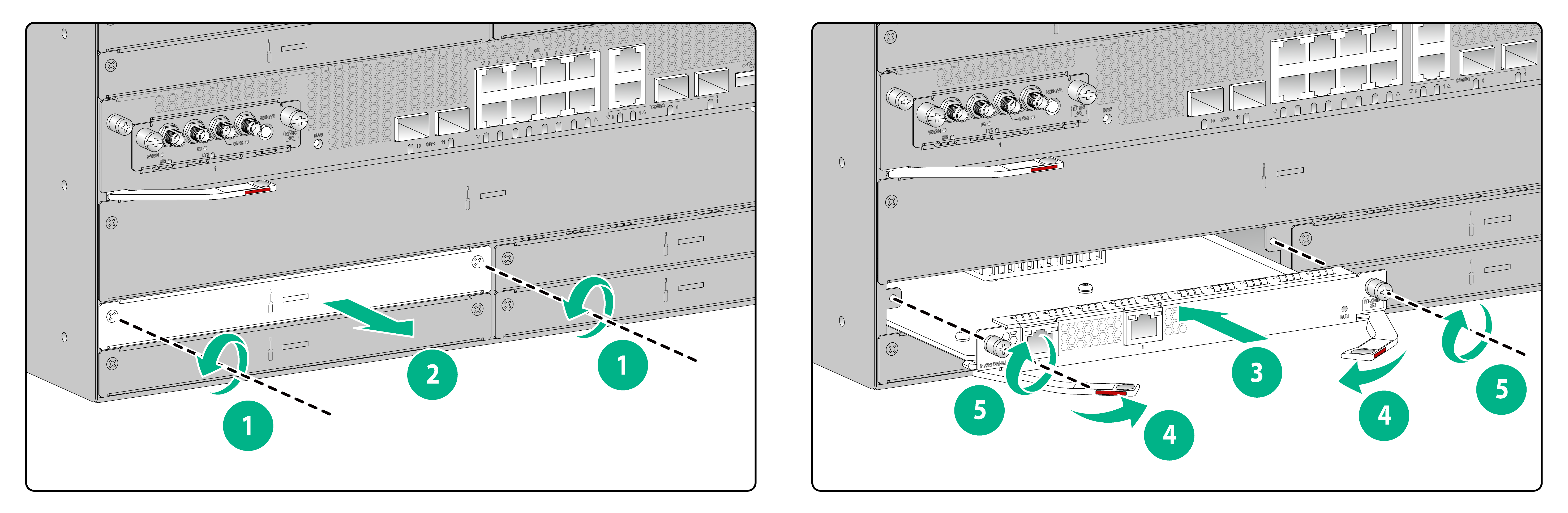
Replacing a SIC interface module
SIC interface modules can be hot swapped. To remove a SIC interface module while device is operating, execute the remove command or press and hold the remove button for more than 3 seconds until the remove LED is off.
To replace a SIC interface module:
1. Put on an ESD wrist strap. Make sure the wrist strap makes good skin contact and is reliably grounded.
2. Use a Phillips screwdriver to loosen the captive screws on the interface module.
3. Pull the module slowly out of the slot along the guide rails.
4. Replace the removed module on an antistatic mat.
Figure8-5 Removing a SIC interface module
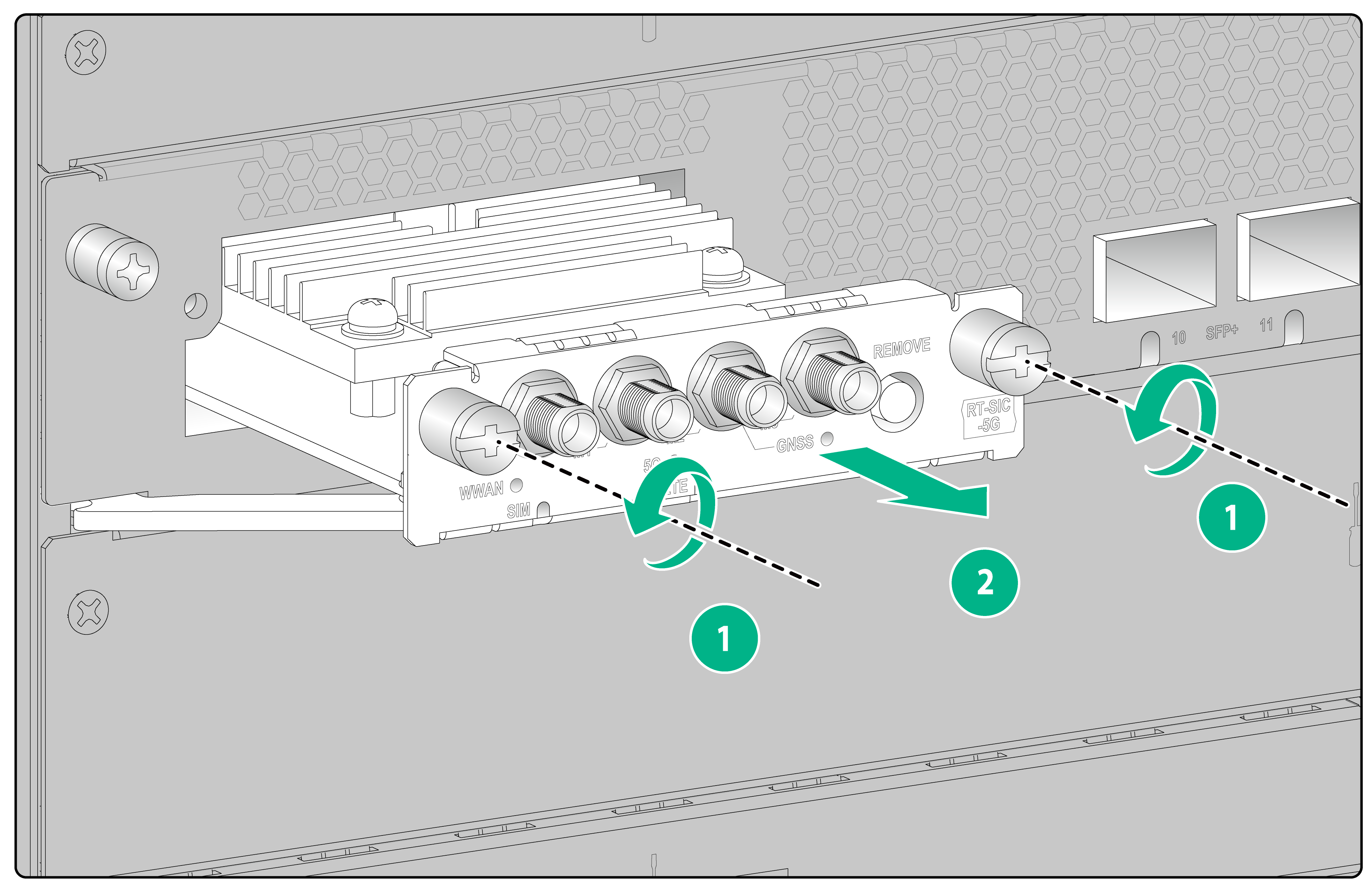
5. Install a filler panel in the slot if you are not to install a new SIC interface module. To install a new SIC interface module, follow the procedure described in "Install a SIC interface module."
Replacing an MSU
1. Put on an ESD wrist strap. Make sure the wrist strap makes good skin contact and is reliably grounded.
2. Use a Phillips screwdriver to loosen the captive screws on the MSU.
3. If the ejector levers on the MSU have locking clips, perform the following tasks:
a. Hold the ejector levers with both hands, press the locking clips with your thumbs, and then pull outward the ejector levers.
b. Pull out the module slowly out of the slot along the guide rails.
4. If the ejector levers on the MSU do not have locking clips, pull outward the two ejector levers of the module and then pull out the module slowly out of the slot along the guide rails.
5. Place the removed module on an antistatic mat.
Figure8-6 Removing an MSU (with ejector levers that do not have locking clips)
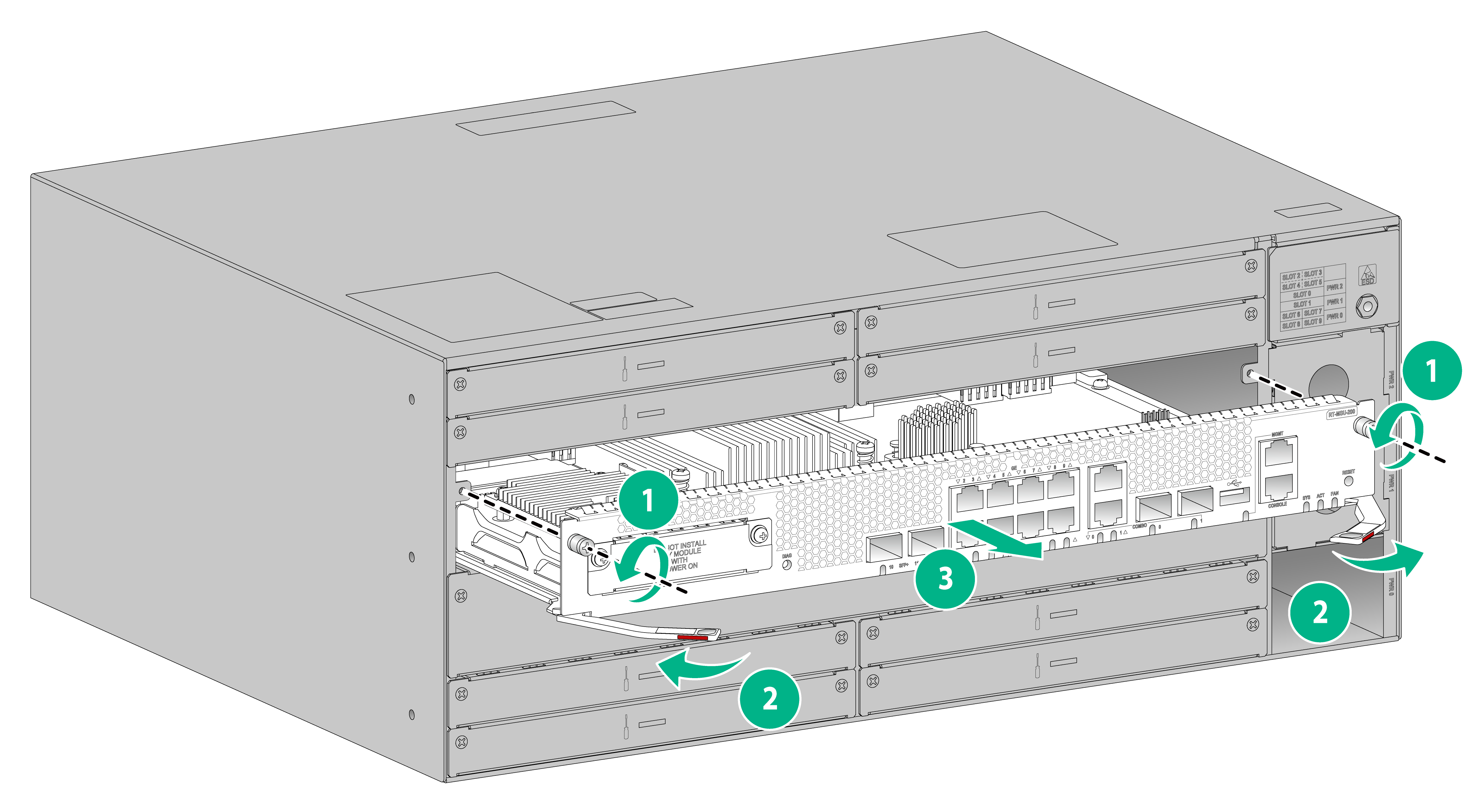
Figure8-7 Removing an MSU (with ejector levers that have locking clips)

6. Install a filler panel in the slot if you are not to install a new MSU. To install a new MSU, follow the procedure described in "Installing a main-control and service-processing unit (MSU)."
9 Hardware management and maintenance
The command lines and outputs vary by software version. For more information about the command lines and their outputs, see the command references for the specific software version.
Displaying software and hardware version information for the device
Use the display version command to display software and hardware version information for the device. This command also displays the system running time and the type and running time of each module.
<Sysname> display version
Displaying device operating information
During daily maintenance or when a fault occurs, you need to view the running information of each functional module to locate the issue.
You can use one of the following methods to collect operating statistics for diagnostics and troubleshooting:
· Use separate display commands, such as display clock, display version, display device, and display current-configuration to collect operating information feature by feature or module by module.
· Use the display diagnostic-information command to save or display operating information for multiple or all features and hardware modules.
¡ Save operating information for multiple or all features and hardware modules:
<Sysname> display diagnostic-information
Save or display diagnostic information (Y=save, N=display)? [Y/N]:y
Please input the file name(*.tar.gz)[flash:/diag_H3C_20230504-154112.tar.gz]:diag.tar.gz
Diagnostic information is outputting to flash:/diag.tar.gz.
Please wait...
Save successfully.
To save storage space, this command automatically compresses the information before saving the information to a file. To view the file content:
# Use the tar extract archive-file command to extract the file.
# Use the gunzip command to decompress the extracted file.
# Use the more command to view the content of the decompressed file.
¡ Save operating information for multiple or all features and hardware modules:
<Sysname> display diagnostic-information
Save or display diagnostic information (Y=save, N=display)? [Y/N]:n
===============================================
===============display clock===============
14:03:55 UTC Thu 01/05/2023
=================================================
===============display version===============
…
Displaying detailed device information
Use the display device verbose command to display detailed information about the device and the modules.
<Sysname> display device verbose
Slot No. Board type Status Primary SubSlots
---------------------------------------------------------------
0 RT-MSU-200 Normal Standby 1
1 RT-MSU-200 Normal Master 1
2 N/A Absent N/A N/A
3 N/A Absent N/A N/A
4 N/A Absent N/A N/A
5 N/A Absent N/A N/A
6 RT-XMIM-8GEE-R Normal N/A 0
7 RT-XMIM-2POS Normal N/A 0
8 N/A Absent N/A N/A
9 RT-XMIM-4E1-F Normal N/A 0
Slot 0: RT-MSU-200
Subslot No. Board Type Status Max Ports
--------------------------------------------------------------
0 Fixed SubCard on Board Normal 14
Slot 1: RT-MSU-200
Subslot No. Board Type Status Max Ports
--------------------------------------------------------------
0 Fixed SubCard on Board Normal 14
Slot 6: RT-XMIM-8GEE-R
Subslot No. Board Type Status Max Ports
--------------------------------------------------------------
0 Fixed SubCard on Board Normal 8
Slot 7: RT-XMIM-2POS
Subslot No. Board Type Status Max Ports
--------------------------------------------------------------
0 Fixed SubCard on Board Normal 2
Slot 9: RT-XMIM-4E1-F
Subslot No. Board Type Status Max Ports
--------------------------------------------------------------
0 Fixed SubCard on Board Normal 4
Slot 0: RT-MSU-200
Subslot 0
Status: Normal
Type: Fixed SubCard on Board
Hardware: Ver.A
Driver: 1.0
CPLD: 1.0
Slot 1: RT-MSU-200
Subslot 0
Status: Normal
Type: Fixed SubCard on Board
Hardware: Ver.A
Driver: 1.0
CPLD: 1.0
Slot 6: RT-XMIM-8GEE-R
Subslot 0
Status: Normal
Type: Fixed SubCard on Board
Hardware: Ver.B
Driver: 1.0
CPLD: 241.0
Slot 7: RT-XMIM-2POS
Subslot 0
Status: Normal
Type: Fixed SubCard on Board
Hardware: Ver.B
Driver: 1.0
CPLD: 1.0
FPGA: 1.00
Slot 9: RT-XMIM-4E1-F
Subslot 0
Status: Normal
Type: Fixed SubCard on Board
Hardware: Ver.A
Driver: 1.0
CPLD: 1.0
FPGA: 5.00
Use the display device slot slot-number command to display detailed information about a module.
<Sysname> display device slot 1
Slot 1: RT-MSU-200
Subslot No. Board Type Status Max Ports
--------------------------------------------------------------
0 Fixed SubCard on Board Normal 14
Table9-1 Command output
|
Field |
Description |
|
Slot No |
Slot number. |
|
Board Type |
Hardware type of the module. |
|
Status |
Module status: · Absent—The slot is empty. · Fault—The module in the slot is faulty and cannot start up. · Normal—The module is operating correctly. |
|
Primary |
Role of the module. · Master—The module is the active MSU. · Standby—The module is the standby MSU. |
|
Max Ports |
Number of ports on the module. |
Displaying electrical label information for the device
Use the display device manuinfo command to display electrical label information for the device.
An electronic label contains the permanent configuration information, including the name, hardware serial number, manufacturing date, MAC address, and vendor name of the device and modules.
<Sysname> display device manuinfo
Chassis self:
DEVICE_NAME:NONE
DEVICE_SERIAL_NUMBER:NONE
MAC_ADDRESS:NONE
MANUFACTURING_DATE:NONE
VENDOR_NAME:NONE
Slot 0 CPU 0:
DEVICE_NAME:NONE
DEVICE_SERIAL_NUMBER:NONE
MAC_ADDRESS:NONE
MANUFACTURING_DATE:NONE
VENDOR_NAME:NONE
Slot 1 CPU 0:
DEVICE_NAME:RT-MSU200
DEVICE_SERIAL_NUMBER:2102A6VT6228VM000300
MAC_ADDRESS:0020-E212-3451
MANUFACTURING_DATE:2019-09-18
VENDOR_NAME:H3C
Slot 6:
DEVICE_NAME:RT-XMIC-8GEE-R
DEVICE_SERIAL_NUMBER:219801XXX3X199000001
MAC_ADDRESS:000F-E212-3451
MANUFACTURING_DATE:2019-09-18
VENDOR_NAME:H3C
Slot 7:
DEVICE_NAME:RT-XMIM-SP4
DEVICE_SERIAL_NUMBER:210231AK62X199000001
MAC_ADDRESS:0010-E212-3451
MANUFACTURING_DATE:2022-09-18
VENDOR_NAME:H3C
Slot 9:
DEVICE_NAME:RT-XMIM-4E1
DEVICE_SERIAL_NUMBER:2102A6VL6229VM000B00
MAC_ADDRESS:00EF-E212-3451
MANUFACTURING_DATE:2022-12-09
VENDOR_NAME:H3C
Fan 0:
DEVICE_NAME:NONE
DEVICE_SERIAL_NUMBER:NONE
MAC_ADDRESS:NONE
MANUFACTURING_DATE:NONE
VENDOR_NAME:NONE
Power 1:
DEVICE_NAME:NONE
DEVICE_SERIAL_NUMBER:NONE
MAC_ADDRESS:NONE
MANUFACTURING_DATE:NONE
VENDOR_NAME:NONE
Power 2:
DEVICE_NAME:NONE
DEVICE_SERIAL_NUMBER:NONE
MAC_ADDRESS:NONE
MANUFACTURING_DATE:NONE
VENDOR_NAME:NONE
Use the display device manuinfo slot slot-number command to display electrical label information for a module.
<Sysname> display device manuinfo slot 1
Slot 1 CPU 0:
DEVICE_NAME:RT-MSU200
DEVICE_SERIAL_NUMBER:2102A6VT6228VM000300
MAC_ADDRESS:0020-E212-3451
MANUFACTURING_DATE:2019-09-18
VENDOR_NAME:H3C
Table9-2 Command output
|
Field |
Description |
|
DEVICE_NAME |
Name of the device or module. |
|
DEVICE_SERIAL_NUMBER |
Serial number of the device or module. |
|
MAC_ADDRESS |
MAC address of the device or module. |
|
MANUFACTURING_DATE |
Manufacturing date of the device or module. |
|
VENDOR_NAME |
Vendor name of the device or module. |
Displaying CPU usage information
Use the display cpu-usage command to display CPU usage information for the device.
<Sysname> display cpu-usage
Slot 1 CPU 0 CPU usage:
38% in last 5 seconds
38% in last 1 minute
40% in last 5 minutes
Table9-3 Output description
|
Field |
Description |
|
38% in last 5 seconds |
Average CPU usage in the most recent 5 seconds. (After the device boots, the device calculates and records the average CPU usage at intervals of 5 seconds.) |
|
38% in last 1 minute |
Average CPU usage in the most recent minute. (After the device boots, the device calculates and records the average CPU usage at intervals of 1 minute.) |
|
40% in last 5 minutes |
Average CPU usage in the most recent 5 minutes. (After the device boots, the device calculates and records the average CPU usage at intervals of 5 minutes.) |
Displaying memory usage information
Use the display memory command to display memory usage information for the device.
Memory statistics are measured in KB(Available):
Slot 0:
Total Used Free Shared Buffers Cached FreeRatio
Mem: 3163656 1790792 1372864 0 9380 612432 43.9%
-/+ Buffers/Cache: 1168980 1994676
Swap: 0 0 0
Slot 1:
Total Used Free Shared Buffers Cached FreeRatio
Mem: 3163656 1901780 1261876 0 9516 617592 40.4%
-/+ Buffers/Cache: 1274672 1888984
Swap: 0 0 0
Container memory statistics are measured in KB(Available):
Slot 0:
Total Used Free UsageRatio
Mem: 3163656 907124 1372864 28.7%
Slot 1:
Total Used Free UsageRatio
Mem: 3163656 993820 1261876 31.4%
Table9-4 Command output
|
Field |
Description |
|
Memory statistics are measured in KB(Available) |
Memory usage information. |
|
Total |
Total size of the physical memory space that can be allocated. The memory space is virtually divided into two parts. Part 1 is used for kernel codes, kernel management, and ISSU functions. Part 2 can be allocated and used for such tasks as running service modules and storing files. The size of part 2 equals the total size minus the size of part 1. |
|
Used |
Used physical memory. |
|
Free |
Free physical memory. |
|
Shared |
Physical memory shared by processes. If this field is not supported, two hyphens (--) are displayed. |
|
Buffers |
Physical memory used for buffers. If this field is not supported, two hyphens (--) are displayed. |
|
Cached |
Physical memory used for caches. If this field is not supported, two hyphens (--) are displayed. |
|
FreeRatio |
Free memory ratio. |
|
-/+ Buffers/Cache |
-/+ Buffers/Cache:used = Mem:Used – Mem:Buffers – Mem:Cached, which indicates the physical memory used by applications. -/+ Buffers/Cache:free = Mem:Free + Mem:Buffers + Mem:Cached, which indicates the physical memory available for applications. |
|
Swap |
Swap memory. |
|
Container memory statistics are measured in KB(Available) |
· Total—Physical memory allocable to Comware containers, in KB. · Used—Physical memory used by Comware containers, in KB. · Free—Free physical memory available for Comware containers, in KB. · UsageRatio—Comware container memory usage ratio. |
Displaying the fan tray operating status
Use the display fan command to display the fan tray operating status.
<Sysname> display fan
Fan No. State Speed
-----------------------------
0 Normal 50
1 Absent N/A
Table9-5 Command output
|
Field |
Description |
|
Fan No |
Slot number of the fan tray. |
|
State |
State of the fan tray: · Normal—The fan tray is operating correctly. · Absent—No fan tray is present. · Fault—The fan tray is faulty. |
|
Speed |
Speed of the fan tray, in percentage to the maximum speed. |
Displaying the power supply operating status
Use the display power-supply command to the power supply operating status.
<Sysname> display power-supply
PWR No. State
-----------------
0 Absent
1 Normal
2 Normal
Table9-6 Command output
|
Field |
Description |
|
Power No |
Slot number of the power supply. |
|
State |
State of the power supply: · Normal—The power supply is operating correctly. · Absent—No power supply is present. · Fault—The power supply is faulty. |
Displaying device temperature information
Use the display environment command to display device temperature information.
<Sysname> display environment
System temperature information (degree centigrade):
------------------------------------------------------------------------------
Slot Sensor Temperature LowerLimit WarningLimit AlarmLimit ShutdownLimit
0 Inflow 1 47 0 62 67 N/A
0 Hotspot 1 61 0 84 98 N/A
0 Hotspot 2 75 0 88 102 107
0 Hotspot 3 68 0 100 117 122
1 Inflow 1 46 0 62 67 N/A
1 Hotspot 1 61 0 84 98 N/A
1 Hotspot 2 77 0 88 102 107
1 Hotspot 3 64 0 100 117 122
Table9-7 Command output
|
Field |
Description |
|
System Temperature information (degree centigrade) |
Temperature information (°C). |
|
Sensor |
Temperature sensor: · hotspot—Hotspot sensor. · inflow—Air inlet sensor. · outflow—Air outlet sensor. |
|
Temperature |
Current temperature. |
|
LowerLimit |
Lower temperature limit. If the device does not support this field, this field displays NA. |
|
WarningLimit |
Warning temperature threshold. If the device does not support this field, this field displays NA. |
|
AlarmLimit |
Alarming temperature threshold. If the device does not support this field, this field displays NA. |
|
ShutdownLimit |
Shutdown temperature threshold. When the sensor temperature reaches the limit, the system shuts down automatically. If the device does not support this field, this field displays NA. |
Displaying transceiver module information and diagnosing transceiver modules
Displaying transceiver module information
Use the display transceiver interface command to display the key parameters of transceiver modules, including the transceiver module type, connector type, central wavelength of the transmit laser, signal transmission distance, and vendor name.
To display transceiver module information:
|
Task |
Command |
Remarks |
|
Display key parameters of transceiver modules. |
display transceiver interface [ interface-type interface-number ] |
Available for all transceiver modules. |
Diagnosing transceiver modules
The device provides the alarm and digital diagnosis functions for transceiver modules. When a transceiver module fails or is not operating correctly, you can perform the following tasks:
· Check the alarms on the transceiver module to identify the fault source.
· Examine the key parameters monitored by the digital diagnosis function, including the temperature, voltage, laser bias current, TX power, and RX power.
To diagnose a transceiver module:
|
Task |
Command |
Remarks |
|
Display transceiver alarms. |
display transceiver alarm interface [ interface-type interface-number ] |
Available for all transceiver modules. |
Saving the running configuration
|
|
IMPORTANT: You must save the running configuration to a .cfg configuration file. |
You can use one of the following methods to save the running configuration:
· Fast mode—Use the save command without the safely keyword. In this mode, the device directly overwrites the target next-startup configuration file. If a reboot or power failure occurs during this process, the next-startup configuration file is lost. You must specify a new startup configuration file after the device reboots.
· Safe mode—Use the save command with the safely keyword. Safe mode is slower than fast mode, but more secure. In safe mode, the system saves the configuration in a temporary file and starts overwriting the target next-startup configuration file after the save operation is complete. If a reboot or power failure occurs during the save operation, the next-startup configuration file is still retained. Use the safe mode if the power source is not reliable or you are remotely configuring the device.
To save the running configuration:
|
Task |
Command |
Remarks |
|
Save the running configuration to a configuration file, without specifying the file as a next-startup configuration file. |
save file-url [ all | slot slot-number ] |
Use either approach. Available in user view. |
|
Save the running configuration to a configuration file in the root directory of the storage medium, and specify the file as a next-startup configuration file. |
save [ safely ] |
Rebooting the device or a module
|
|
CAUTION: · If the main system software image file does not exist, do not use the reboot command to reboot the device. Specify the main system software image file first, and then reboot the device. · The precision of the rebooting timer is 1 minute. 1 minute before the rebooting time, the device prompts "REBOOT IN ONE MINUTE" and reboots in one minute. · If you are performing file operations when the device is to be rebooted, the system does not execute the reboot command for security. |
To reboot the device or a module, use one of the following methods:
· Reboot the device at the CLI.
¡ Reboot the device immediately by using the reboot command.
¡ Schedule a reboot to occur at a specific time or date or after a delay by using the schedule reboot command.
· Power off and then power on the device. This method cuts off the power of the device forcibly, which might cause data loss and hardware damage. It is the least-preferred method.
To reboot a module or the device immediately:
|
Task |
Command |
Remarks |
|
Reboot a module or the device immediately. |
reboot [ slot slot-number ] |
If you do not specify the slot slot-number option, the command reboots the device (including the MSUs and interface modules). Available in user view. |
To schedule a reboot:
|
Task |
Command |
Remarks |
|
Schedule a reboot. |
· Schedule a reboot to occur at a specific time or
date: · Schedule a reboot to occur after a delay: |
Use either approach. By default, no reboot date or time or reboot delay time is specified. Available in user view. |
10 Troubleshooting
Power supply failure
Symptom
The device fails to be powered on, and the status LED on the power supply is off.
Solution
To resolve the issue:
1. Verify that the power cord is connected correctly and reliably.
2. Verify that the power source is as required by the power supply.
3. Verify that the device operates at acceptable temperature ranges and the power supply has good ventilation.
4. If the issue persists, contact H3C Support.
To replace a power supply, see "Replacing a power supply."
Fan tray failure
Symptom
The system reports a fan tray failure:
%May 22 10:13:17:666 2023 H3C DEV/2/FAN_FAILED: Fan 1 failed.
The RUN status LED on the fan tray is steady yellow.
Solution
To resolve the issue:
1. Verify that the air inlet and outlet vents of the chassis are not blocked. Clear the obstructions if any.
2. Replace the fan tray.
3. If the issue persists, contact H3C Support.
Configuration terminal issues
No display
Symptom
The configuration terminal does not have display when the device is powered on.
Solution
To resolve the issue:
1. Verify that the power system is operating correctly.
2. Verify that the console cable is correctly connected.
3. Verify that the console cable does not have any issues and the terminal settings are correct.
4. If the issue persists, contact H3C Support.
Garbled display
Symptom
The display on the configuration terminal is garbled.
Solution
To resolve the issue:
1. Verify that the terminal parameters are configured as follows:
¡ Baud rate—9600.
¡ Data bits—8.
¡ Stop bits—1.
¡ Parity—None.
¡ Flow control—None.
2. If the issue persists, contact H3C Support.
Interface module, cable, and connection failure
Symptom
After an interface module is installed and the device is powered on, the LEDs on the interface module panel indicate that the interface module is operating incorrectly.
Solution
To resolve the issue:
1. Verify that the interface module is installed correctly.
2. Verify that the device supports the interface module.
3. Verify that the interface module is installed in the compatible slot.
4. Verify that a correct cable is used.
5. Verify that the cable is correctly connected.
6. If the issue persists, contact H3C Support.
System failure during operation
Symptom
A system failure occurs during device operation.
Solution
Press the reset button (RESET) to reboot the router.
Guidelines for using the reset button
|
|
IMPORTANT: · The reset button can only reboot the device and cannot restore the device to the factory default. · For the reset button to take effect, you must press it for a minimum of 0.5s. |
· When only one MSU is present on the device, pressing the reset button reboots the device.
· When two MSUs run on the device, pressing the reset button on the active MSU will trigger an active/standby MSU switchover without interrupting the system operation.
· When two MSUs run on the device, pressing the reset button on the standby MSU will reset the standby MSU without affecting the system operation.
