- Table of Contents
-
- 06-Layer 3—IP Services Configuration Guide
- 00-Preface
- 01-ARP configuration
- 02-IP addressing configuration
- 03-DNS configuration
- 04-IP forwarding basics configuration
- 05-Fast forwarding configuration
- 06-Adjacency table configuration
- 07-IRDP configuration
- 08-IP performance optimization configuration
- 09-UDP helper configuration
- 10-IPv6 basics configuration
- 11-IPv6 fast forwarding configuration
- 12-Tunneling configuration
- 13-GRE configuration
- 14-ADVPN configuration
- 15-HTTP redirect configuration
- Related Documents
-
| Title | Size | Download |
|---|---|---|
| 04-IP forwarding basics configuration | 162.70 KB |
Contents
Configuring IP forwarding basic settings························································ 1
About FIB table······························································································································· 1
Saving the IP forwarding entries to a file··························································································· 1
Enabling IPv4 packet forwarding on an interface with no IPv4 address configured······························ 2
Enabling IPv6 packet forwarding on an interface with no IPv6 address configured······························ 2
Enabling FIB route switching optimization························································································· 3
Specifying the maximum number of FIB entries on an interface module·············································· 3
Performing one-time FIB entry synchronization·················································································· 4
Enabling FIB logging······················································································································· 4
Enabling SNMP notifications for FIB events······················································································ 4
Enabling SNMP notifications for IP forwarding events······································································· 5
Display and maintenance commands for FIB table············································································ 5
Configuring load sharing··················································································· 7
About load sharing·························································································································· 7
Configuring per-packet or per-flow load sharing················································································ 7
Enabling bandwidth-based load sharing·························································································· 11
Loading sharing configuration examples························································································· 11
Example: Configuring load sharing based on source and destination addresses························ 11
Configuring IP forwarding basic settings
About FIB table
A device uses the FIB table to make packet forwarding decisions.
A device selects optimal routes from the routing table, and puts them into the FIB table. Each FIB entry specifies the next hop IP address and output interface for packets destined for a specific subnet or host.
For more information about the routing table, see Layer 3—IP Routing Configuration Guide.
Use the display fib command to display the FIB table. The following example displays the entire FIB table.
<Sysname> display fib
Route destination count: 4
Directly-connected host count: 0
Flag:
U:Usable G:Gateway H:Host B:Blackhole D:Dynamic S:Static
R:Relay F:FRR
Destination/Mask Nexthop Flag OutInterface/Token Label
10.2.0.0/16 10.2.1.1 U XGE3/1/1 Null
10.2.1.1/32 127.0.0.1 UH InLoop0 Null
127.0.0.0/8 127.0.0.1 U InLoop0 Null
127.0.0.1/32 127.0.0.1 UH InLoop0 Null
A FIB entry includes the following items:
· Destination—Destination IP address.
· Mask—Network mask. The mask and the destination address identify the destination network. A logical AND operation between the destination address and the network mask yields the address of the destination network. For example, if the destination address is 192.168.1.40 and the mask 255.255.255.0, the address of the destination network is 192.168.1.0. A network mask includes a certain number of consecutive 1s. It can be expressed in dotted decimal format or by the number of the 1s.
· Nexthop—IP address of the next hop.
· Flag—Route flag.
· OutInterface—Output interface.
· Token—Label Switched Path index number.
· Label—Inner label.
Saving the IP forwarding entries to a file
Restrictions and guidelines
The feature automatically creates the file if you specify a nonexistent file. If the file already exists, this feature overwrites the file content.
This feature triggers one-time saving of the IP forwarding entries.
To automatically save the IP forwarding entries periodically, configure a schedule for the device to automatically run the ip forwarding-table save command. For information about scheduling a task, see Fundamentals Configuration Guide.
Procedure
To save the IP forwarding entries to a file, execute the following command in any view:
ip forwarding-table save filename filename
Enabling IPv4 packet forwarding on an interface with no IPv4 address configured
About this task
On a device that supports both IPv4 and IPv6, the next hop of an IPv4 packet might be an IPv4 address or an IPv6 address. If the output interface has no IPv4 address configured, the interface cannot forward the IPv4 packet. To solve this problem, enable this feature on the interface. This feature allows the interface to forward IPv4 packets even though the interface has no IPv4 address configured.
Restrictions and guidelines
You can configure this feature in any view in which an IPv4 address can be configured.
Procedure
1. Enter system view.
system-view
2. Enter interface view.
interface interface-type interface-number
3. Enable IPv4 packet forwarding on an interface that has no IPv4 address configured.
ip forwarding
By default, IPv4 packet forwarding is disabled on an interface that has no IPv4 address configured.
Enabling IPv6 packet forwarding on an interface with no IPv6 address configured
About this task
On a device that supports both IPv4 and IPv6, the next hop of an IPv4 packet might be an IPv4 address or an IPv6 address. If the output interface has no IPv6 address configured, the interface cannot forward the IPv6 packet. To solve this problem, enable this feature on the interface. This feature allows the interface to forward IPv6 packets even though the interface has no IPv6 address configured.
Restrictions and guidelines
You can configure this feature in any view in which an IPv6 address can be configured.
Procedure
1. Enter system view.
system-view
2. Enter interface view.
interface interface-type interface-number
3. Enable IPv6 packet forwarding on an interface that has no IPv6 address configured.
ipv6 forwarding
By default, IPv6 packet forwarding is disabled on an interface that has no IPv4 address configured.
Enabling FIB route switching optimization
About this task
This feature is applicable to scenarios with high service traffic sustainability requirements. It enables the device to keep using the current route until the new route becomes available, instead of disconnecting the current route directly. This prevents packet loss caused by route switch, which might take hundreds of milliseconds.
The device can keep using the current route for a maximum of 10 seconds.
Procedure
1. Enter system view.
system-view
2. Enable FIB route switching optimization.
fib switch-enhance
By default, FIB route switching optimization is disabled.
Specifying the maximum number of FIB entries on an interface module
About this task
By default, the maximum number of FIB entries on an interface module is the maximum number of FIB entries supported by the device. To save memory resources, you can perform this task to decrease the maximum number of FIB entries on an interface module.
Restrictions and guidelines
If the value for the max-number argument exceeds the maximum number supported by the device, the configuration does not take effect on interface modules. The maximum number supported by the device is then applied to the interface modules.
If the number of FIB entries has reached max-number on an interface module, the module stops accepting new FIB entries issued by the MPU. The existing services on the module are not affected. If the MPU deletes some old FIB entries and notifies the interface module to delete the entries, the interface module can accept new FIB entries until the upper limit is reached again.
Procedure
1. Enter system view.
system-view
2. Specify the maximum number of FIB entries on an interface module.
fib max-number max-number slot slot-number
By default, the maximum number of FIB entries on an interface module is the maximum number of FIB entries supported by the device.
Performing one-time FIB entry synchronization
About this task
Perform this task to synchronize FIB entries from the MPU to the specified interface module.
Restrictions and guidelines
If the maximum number of IPv4 or IPv6 FIB entries (specified by using the fib max-number or ipv6 fib max-number command) is reached on the interface module, the module stops accepting new entries.
Procedure
1. Enter system view.
system-view
2. Perform one-time FIB entry synchronization.
fib smooth slot slot-number
Enabling FIB logging
About this task
The logs are sent to the information center of the device. For the logs to be output correctly, you must also configure the information center on the device. For more information about information center configuration, see Network Management and Monitoring Configuration Guide.
To avoid memory consumption caused by log recording, you can use the undo fib log enable command to disable FIB logging.
Procedure
1. Enter system view.
system-view
2. Enable FIB logging.
fib log enable
By default, FIB logging is disabled.
Enabling SNMP notifications for FIB events
About this task
This feature enables the FIB module to generate SNMP notifications for critical FIB events, such as the exceeding of the message queue length threshold. The SNMP notifications are sent to the SNMP module. For the SNMP notifications to be sent correctly, you must also configure SNMP. For more information about SNMP configuration, see Network Management and Monitoring Configuration Guide.
Procedure
1. Enter system view.
system-view
2. Enable SNMP notifications for FIB events.
snmp-agent trap enable fib
By default, SNMP notifications for FIB events are enabled.
Enabling SNMP notifications for IP forwarding events
About this task
This feature enables the IP forwarding module to generate SNMP notifications for critical IP forwarding events. The SNMP notifications are sent to the SNMP module. For the SNMP notifications to be sent correctly, you must also configure SNMP. For more information about SNMP configuration, see Network Management and Monitoring Configuration Guide.
Procedure
1. Enter system view.
system-view
2. Enable SNMP notifications for IP forwarding events.
snmp-agent trap enable ip-forwarding
By default, SNMP notifications for IP forwarding events are enabled.
Display and maintenance commands for FIB table
Execute display commands in any view.
|
Task |
Command |
|
Display FIB entries. |
In standalone mode: display fib [ vpn-instance vpn-instance-name ] [ ip-address [ mask | mask-length ] ] [ slot slot-number ] In IRF mode: display fib [ vpn-instance vpn-instance-name ] [ ip-address [ mask | mask-length ] ] [chassis chassis-number slot slot-number] |
|
Display FIB entry statistics. |
In standalone mode: display fib count [ all | vpn-instance vpn-instance-name ] slot slot-number In IRF mode: display fib count [ all | vpn-instance vpn-instance-name ] chassis chassis-number slot slot-number |
|
Display IPv4 data packet forwarding entries cached in the MPU forwarding module. |
In standalone mode: display ip proxy-forward cache [ slot slot-number ] In IRF mode: display ip proxy-forward cache [ chassis chassis-number slot slot-number ] |
|
Display the cached destination IPv4 address entries of packets on the active and standby modules. |
In standalone mode: display ip-cache [ vpn-instance vpn-instance-name ] [ slot slot-number ] In IRF mode: display ip-cache [ vpn-instance vpn-instance-name ] [ chassis chassis-number slot slot-number ] |
Configuring load sharing
About load sharing
If a routing protocol finds multiple equal-cost best routes to the same destination, the device forwards packets over the equal-cost routes to implement load sharing.
Configuring per-packet or per-flow load sharing
About this task
In the per-flow load sharing mode, the device forwards flows over equal-cost routes. Packets of one flow travel along the same routes. You can configure the device to identify a flow based on the following criteria: source IP address, source MAC address, destination IP address, destination MAC address, source port number, destination port number, IP protocol number, and ingress port. You can also configure per-flow load sharing for IP tunnel packets.
In a complex network, when the criteria cannot distinguish flows, you can use the algorithm keyword to specify an algorithm to identify flows.
In the per-packet load sharing mode, the device forwards packets over equal-cost routes.
Restrictions and guidelines
The configuration of per-packet load sharing does not take effect for the following cards:
|
Card category |
Cards |
|
CSPC |
CSPC-GE16XP4L-E, CSPC-GE24L-E, CSPC-GP24GE8XP2L-E |
|
CSPEX |
CSPEX-1104-E, CSPEX-1204 |
The ip-pro keyword is not supported for the following cards:
|
Card category |
Cards |
|
CEPC |
CSPC-GE16XP4L-E, CSPC-GE24L-E, CSPC-GP24GE8XP2L-E, CEPC-CQ8L, CEPC-CQ8LA, CEPC-CQ8L1A, CEPC-CQ8L3A, CEPC-CQ16L1, CEPC-DQ2L1-G |
|
CSPEX |
CSPEX-1304X, CSPEX-1404X, CSPEX-1502X, CSPEX-1504X, CSPEX-1504XA, CSPEX-1602X, CSPEX-1602XA, CSPEX-1804X, CSPEX-1512X, CSPEX-1612X, CSPEX-1812X, CSPEX-1502XA, CSPEX-1802X, CSPEX-1802XA, CSPEX-1812X-E, CSPEX-2304X-G, CSPEX-2304X-LG, CSPEX-2612XA, CSPEX-2612X3A |
|
SPE |
RX-SPE200, RX-SPE200-E |
The ip-tos keyword is not supported for the following cards:
|
Card category |
Cards |
|
CEPC |
CEPC-CQ8L, CEPC-CQ8LA, CEPC-CQ8L1A, CEPC-CQ8L3A, CEPC-CQ16L1, CEPC-DQ2L1-G |
|
CSPEX |
CSPEX-1502XA, CSPEX-1802X, CSPEX-1802XA, CSPEX-1812X-E, CSPEX-2304X-G, CSPEX-2304X-LG, CSPEX-2612XA, CSPEX-2612X3A |
|
SPE |
RX-SPE200-E |
On the cards listed in the following table, the per-flow load sharing modes take effect in the following order:
|
Card category |
Cards |
|
CEPC |
CEPC-XP4LX, CEPC-XP24LX, CEPC-XP48RX, CEPC-CP4RX, CEPC-CP4RXA, CEPC-CP4RX-L, CEPC-CQ8LA, CEPC-CQ16L1, CEPC-CQ8L1A |
|
CSPEX |
CSPEX-1304X, CSPEX-1404X, CSPEX-1502X, CSPEX-1504X, CSPEX-1504XA, CSPEX-1602X, CSPEX-1602XA, CSPEX-1804X, CSPEX-1512X, CSPEX-1612X, CSPEX-1812X, CSPEX-1802XA, CSPEX-2612XA |
|
SPE |
RX-SPE200 |
1. Algorithm-based per-flow load sharing configured globally or on the card (specified by the algorithm algorithm-number option).
2. Per-flow load sharing with a random combination of the dest-ip, dest-mac, dest-port, src-ip, src-mac, and src-port keywords on the card.
3. Global per-flow load sharing with a random combination of the dest-ip, dest-mac, dest-port, src-ip, src-mac, and src-port keywords.
4. Link-aggregation load sharing mode (configured by using the link-aggregation global load-sharing mode command). For more information, see Ethernet link aggregation configuration in Layer 2—LAN Switching Configuration Guide.
5. Global default load sharing mode.
For the CSPEX-1802X, CSPEX-1812X-E, CEPC-CQ8L, CSPEX-2304X-G, CSPEX-2304X-LG, RX-SPE200-E, and CSPEX-1502XA cards, the per-flow load sharing modes take effect on a card in the following order:
6. Algorithm-based per-flow load sharing configured globally or on the card (specified by the algorithm algorithm-number option).
7. Per-flow load sharing with a random combination of the dest-ip, dest-mac, dest-port, src-ip, src-mac, and src-port keywords on the card.
8. Global per-flow load sharing with a random combination of the dest-ip, dest-mac, dest-port, src-ip, src-mac, and src-port keywords.
9. Global default load sharing mode.
Procedure
1. Enter system view.
system-view
2. Configure load sharing.
In standalone mode:
ip load-sharing mode { per-flow [ algorithm algorithm-number | [ dest-ip | dest-mac | dest-port | ip-pro | src-ip | src-mac | src-port | ip-tos ] *| per-packet } { global | slot slot-number [ cpu cpu-number ] }
In IRF mode:
ip load-sharing mode { per-flow [ algorithm algorithm-number | [ dest-ip | dest-mac | dest-port | ip-pro | src-ip | src-mac | src-port | ip-tos ] *| per-packet } { chassis chassis-number slot slot-number [ cpu cpu-number ] | global }
The device implements per-flow load sharing.
· For fragmented packets, the default load sharing modes are dest-ip and src-ip.
· For non-fragmented packets:
¡ For the default load sharing modes used by the cards below, see Table 1.
|
Forwarded packet type |
Load sharing mode |
|
CEPC |
CEPC-XP4LX, CEPC-XP24LX, CEPC-XP48RX, CEPC-CP4RX, CEPC-CP4RXA, CEPC-CP4RX-L |
|
CSPEX |
CSPEX-1304X, CSPEX-1404X, CSPEX-1502X, CSPEX-1504X, CSPEX-1504XA, CSPEX-1602X, CSPEX-1602XA, CSPEX-1804X, CSPEX-1512X, CSPEX-1612X, CSPEX-1812X |
|
SPE |
RX-SPE200 |
Table 1 Default load sharing modes (1)
|
Packet type |
Default load sharing mode |
|
IP unicast packets |
dest-ip, src-ip |
|
IP multicast packets |
dest-mac, src-mac |
|
Layer 2 frames |
dest-mac, src-mac |
|
MPLS L3VPN packets |
dest-ip, src-ip |
|
MPLS L2VPN packets |
· IP packets: dest-ip, src-ip · Other packets: dest-mac, src-mac |
|
MPLS LSPs |
· IP packets: mpls-label1, mpls-label2, dest-ip, src-ip · Other packets: mpls-label1, mpls-label2, dest-mac, src-mac |
|
Other MPLS packets |
mpls-label1, mpls-label2 |
|
IP tunnel packets |
· IP packets: inner dest-ip, inner src-ip · Non-termination MPLS packets: mpls-label1, mpls-label2 |
¡ For the default load sharing modes used by the cards below, see Table 2.
|
Forwarded packet type |
Load sharing mode |
|
CEPC |
CEPC-CQ8L, CEPC-CQ8LA, CEPC-CQ8L1A, CEPC-CQ8L3A, CEPC-CQ16L1, CEPC-DQ2L1-G |
|
CSPEX |
CSPEX-1502XA, CSPEX-1802X, CSPEX-1802XA, CSPEX-1812X-E, CSPEX-2304X-G, CSPEX-2304X-LG, CSPEX-2612XA, CSPEX-2612X3A |
|
SPE |
RX-SPE200-E |
Table 2 Default load sharing modes (2)
|
Packet type |
Default load sharing mode |
|
IP unicast packets |
dest-ip, src-ip, dest-port, src-port |
|
IP multicast packets |
dest-ip, src-ip, dest-port, src-port |
|
Layer 2 frames |
dest-mac, src-mac |
|
MPLS L3VPN packets |
dest-ip, src-ip, dest-port, src-port |
|
MPLS L2VPN packets |
· IP packets: dest-ip, src-ip, dest-port, src-port · Other packets: dest-mac, src-mac |
|
MPLS LSPs |
· IP packets: mpls-label1, mpls-label2, dest-ip, src-ip, dest-port, src-port · Other packets: mpls-label1, mpls-label2, dest-mac, src-mac |
|
Other MPLS packets |
mpls-label1, mpls-label2 |
|
IP tunnel packets |
· IP packets: inner dest-ip, inner src-ip, inner src-port, inner dest-port · Non-termination MPLS packets: mpls-label1, mpls-label2 |
¡ For the default load sharing modes used by the cards below, see Table 3.
|
Forwarded packet type |
Load sharing mode |
|
CEPC |
CSPC-GE16XP4L-E, CSPC-GE24L-E, CSPC-GP24GE8XP2L-E |
|
CSPEX |
CSPEX-1104-E, CSPEX-1204 |
Table 3 Default load sharing modes (3)
|
Packet type |
Default load sharing mode |
|
IP unicast packets |
dest-ip, src-ip |
|
IP multicast packets |
dest-mac, src-mac |
|
Layer 2 frames |
dest-mac, src-mac |
|
MPLS L3VPN packets |
dest-ip, src-ip |
|
MPLS L2VPN packets |
· IP packets: dest-ip, src-ip · MPLS VPLS packets: dest-mac, src-mac · MPLS L2VPN packets: mpls-label1, mpls-label2 · Other packets: dest-mac, src-mac |
|
MPLS LSPs |
mpls-label1, mpls-label2 |
|
Other MPLS packets |
mpls-label1, mpls-label2 |
|
IP tunnel packets |
· IP packets: inner dest-ip, inner src-ip · Non-termination MPLS packets: mpls-label1, mpls-label2 |
Enabling bandwidth-based load sharing
About this task
This feature load shares flow traffic among multiple output interfaces based on their load percentages. The device calculates the load percentage for each output interface in terms of the interface expected bandwidth.
Devices that run load sharing protocols, such as Locator/ID Separation Protocol (LISP), implement load sharing based on the ratios defined by these protocols.
Restrictions and guidelines
Only the incoming traffic on the following cards supports bandwidth-based IPv4 load sharing:
|
Card category |
Cards |
|
CEPC |
CEPC-XP4LX, CEPC-XP24LX, CEPC-XP48RX, CEPC-CP4RX, CEPC-CP4RXA, CEPC-CP4RX-L, CEPC-CQ8L, CEPC-CQ8LA, CEPC-CQ8L1A, CEPC-CQ8L3A, CEPC-CQ16L1, CEPC-DQ2L1-G |
|
CSPEX |
CSPEX-1304X, CSPEX-1404X, CSPEX-1502X, CSPEX-1504X, CSPEX-1504XA, CSPEX-1602X, CSPEX-1602XA, CSPEX-1804X, CSPEX-1512X, CSPEX-1612X, CSPEX-1812X, CSPEX-1502XA, CSPEX-1802X, CSPEX-1802XA, CSPEX-1812X-E, CSPEX-2304X-G, CSPEX-2304X-LG, CSPEX-2612XA, CSPEX-2612X3A |
|
SPE |
RX-SPE200, RX-SPE200-E |
Procedure
1. Enter system view.
system-view
2. Enable IPv4 bandwidth-based load sharing.
bandwidth-based-sharing
By default, the IPv4 bandwidth-based load sharing is disabled.
3. (Optional.) Configure the expected bandwidth of the interface.
a. Enter interface view.
interface interface-type interface-number
b. Configure the expected bandwidth of the interface.
bandwidth bandwidth
By default, the expected bandwidth is the physical bandwidth of the interface.
Loading sharing configuration examples
Example: Configuring load sharing based on source and destination addresses
Network configuration
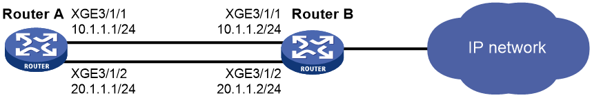
As shown in Figure 1, Router A has two equal-cost routes to Router B. Configure load sharing on Router A to forward packets through Router B to the destination IP address 1.2.3.4/24.
Procedure
# On Router A, assign IP addresses to interfaces.
<RouterA> system-view
[RouterA] interface ten-gigabitethernet 3/1/1
[RouterA-Ten-GigabitEthernet3/1/1] ip address 10.1.1.1 24
[RouterA-Ten-GigabitEthernet3/1/1] quit
[RouterA] interface ten-gigabitethernet 3/1/2
[RouterA-Ten-GigabitEthernet3/1/2] ip address 20.1.1.1 24
[RouterA-Ten-GigabitEthernet3/1/2] quit
# On Router B, assign IP addresses to interfaces.
<RouterB> system-view
[RouterB] interface ten-gigabitethernet 3/1/1
[RouterB-Ten-GigabitEthernet3/1/1] ip address 10.1.1.2 24
[RouterB-Ten-GigabitEthernet3/1/1] quit
[RouterB] interface ten-gigabitethernet 3/1/2
[RouterB-Ten-GigabitEthernet3/1/2] ip address 20.1.1.2 24
[RouterB-Ten-GigabitEthernet3/1/2] quit
# On Router A, configure two static routes to the destination IP address.
[RouterA] ip route-static 1.2.3.4 24 10.1.1.2
[RouterA] ip route-static 1.2.3.4 24 20.1.1.2
[RouterA] quit
# On Router A, display FIB entries matching the destination IP address 1.2.3.4.
<RouterA> display fib 1.2.3.4
FIB entry count: 2
Flag:
U:Usable G:Gateway H:Host B:Blackhole D:Dynamic S:Static
R:Relay F:FRR
Destination/Mask Nexthop Flag OutInterface/Token Label
1.2.3.0/24 10.1.1.2 USGR XGE3/1/1 Null
1.2.3.0/24 20.1.1.2 USGR XGE3/1/2 Null
# On Router A, configure per-flow load sharing based on the source IP address and destination IP address.
<RouterA> system-view
[RouterA] ip load-sharing mode per-flow dest-ip src-ip global
[RouterA] quit
Verifying the configuration
# Verify that Router A implements load sharing.
<RouterA> display counters outbound interface Ten-GigabitEthernet
Interface Total (pkts) Broadcast (pkts) Multicast (pkts) Err (pkts)
XGE3/1/1 1045 0 0 0
XGE3/1/2 1044 0 0 0
