- Table of Contents
-
- 03-Interface Configuration Guide
- 00-Preface
- 01-Bulk interface configuration
- 02-Ethernet interface configuration
- 03-WAN interface configuration
- 04-POS interface configuration
- 05-CPOS interface configuration
- 06-ATM interface configuration
- 07-Loopback, null, and inloopback interface configuration
- 08-FlexE interface configuration
- Related Documents
-
| Title | Size | Download |
|---|---|---|
| 02-Ethernet interface configuration | 411.73 KB |
Contents
Configuring Ethernet interfaces
Enabling SNMP interface index constancy
Configuring a management Ethernet interface
Configuring common Ethernet interface settings
Ethernet interface naming conventions
Configuring the physical type for a combo interface (single combo interface)
Splitting a 40-GE interface and combining 10-GE breakout interfaces
Changing a 100-GE interface to a 40-GE interface
Changing a 100-GE interface to a 50-GE interface
Changing a 25-GE interface to a 10-GE interface
Changing the interface type of a 10-GE interface
Configuring the operating mode for a 10-GE interface
Configuring the framing format for a 10-GE interface operating in WAN mode
Setting the J0 and J1 overhead bytes for a 10-GE interface
Configuring basic settings of an Ethernet interface
Configuring basic settings of an Ethernet subinterface
Configuring the link mode of an Ethernet interface
Configuring jumbo frame support
Configuring physical state change suppression on an Ethernet interface
Configuring dampening on an Ethernet interface
Enabling link flapping protection on an interface
Configuring generic flow control on an Ethernet interface
Configuring PFC on an inner interface
Setting the statistics polling interval
Enabling interframe gap and preamble statistics in the traffic statistics
Enabling loopback testing on an Ethernet interface
Configuring interface alarm functions
Configuring SNMP notifications for cards
Displaying the operating status and information of an interface
Shutting down all physical interfaces
Restoring the default settings for an interface
Configuring a Layer 3 Ethernet interface
Enabling Layer 2 forwarding on an interface
Setting the MTU for an Ethernet interface or subinterface
Setting the MAC address of an Ethernet interface
Enabling packet statistics collection on a Layer 3 Ethernet subinterface
Display and maintenance commands for an Ethernet interface or subinterface
Configuring Ethernet interfaces
About Ethernet interface
Your device supports the following types of Ethernet interfaces:
· Layer 2 Ethernet interfaces—Physical Ethernet interfaces operating at the data link layer (Layer 2) to switch packets.
· Layer 3 Ethernet interfaces—Physical Ethernet interfaces operating at the network layer (Layer 3) to route packets. You can assign an IP address to a Layer 3 Ethernet interface.
· Layer-configurable Ethernet interfaces—Physical Ethernet interfaces that can be configured to operate in bridge mode as Layer 2 Ethernet interfaces or in route mode as Layer 3 Ethernet interfaces.
· Layer 3 Ethernet subinterfaces—Logical interfaces operating at the network layer. You can assign an IP address to a Layer 3 Ethernet subinterface. To enable a Layer 3 Ethernet interface to transport packets for multiple VLANs, you must create Layer 3 subinterfaces on the Layer 3 Ethernet interface. For information about how a Layer 3 Ethernet subinterface sends and receives VLAN-tagged packets, see Layer 2—LAN Switching Configuration Guide.
Enabling SNMP interface index constancy
About this task
For an application that uses interface indexes for billing, the interface indexes must be constant. You can enable SNMP interface index constancy to make the interface indexes not being affected by adding or deleting interfaces, system reboots, and software or hardware changes. With this command configured, indexes of both the existing interfaces and newly created interfaces are constant.
Restrictions and guidelines
Before rebooting the system, execute the save command first. Otherwise, interface indexes on the device might change after the reboot.
Procedure
1. Enter system view.
system-view
2. Enable SNMP interface index constancy.
ifindex-constant enable [ file filename ]
By default, SNMP interface index constancy is disabled.
3. Set the maximum number of constant interface indexes.
ifindex-constant max-number number
By default, the maximum number of constant interface indexes is 131070.
Configuring a management Ethernet interface
About this task
A management interface uses an RJ-45/LC connector. You can connect a management Ethernet interface to a PC for software loading and system debugging, or connect it to a remote NMS for remote system management.
Procedure
4. Enter system view.
system-view
5. Enter management Ethernet interface view.
interface M-GigabitEthernet interface-number
6. (Optional.) Set the interface description.
description text
The default setting is M-GigabitEthernet0/0/0 Interface.
7. (Optional.) Set the duplex mode for the management Ethernet interface.
duplex { auto | full | half }
By default, the duplex mode is auto for a management Ethernet interface.
8. (Optional.)_Set the speed for the management Ethernet interface.
speed { 10 | 100 | 1000 | auto }
By default, the speed is auto for a management Ethernet interface.
9. (Optional.) Shut down the interface.
shutdown
By default, the management Ethernet interface is up.
|
|
CAUTION: Executing the shutdown command on an interface will disconnect the link of the interface and interrupt communication. Use this command with caution. |
Configuring common Ethernet interface settings
Ethernet interface naming conventions
When the device is operating in standalone mode, the Ethernet interfaces are named in the format of interface type A/B/C. The letters that follow the interface type represent the following elements:
· A—Card slot number.
· B—Subcard slot number. If no subcard exists in the card, the value is fixed at 0.
· C—Port index.
When the device is operating in IRF mode, the Ethernet interfaces are named in the format of interface type A/B/C/D. The letters that follow the interface type represent the following elements:
· A—IRF member ID, in the range of 1 to 4.
· B—Card slot number.
· C—Subcard slot number. If no subcard exists in the card, the value is fixed at 0.
· D—Port index.
Configuring the physical type for a combo interface (single combo interface)
About this task
A combo interface is a logical interface that physically comprises one fiber combo port and one copper combo port. The two ports share one forwarding channel and one interface view. As a result, they cannot work simultaneously. When you activate one port, the other port is automatically disabled. In the interface view, you can activate the fiber or copper combo port, and configure other port attributes such as the interface rate and duplex mode.
Prerequisites
Before you configure combo interfaces, complete the following tasks:
· Determine the combo interfaces on your device. Identify the two physical interfaces that belong to each combo interface according to the marks on the device panel.
· Use the display interface command to determine which port (fiber or copper) of each combo interface is active:
¡ If the copper port is active, the output includes "Media type is twisted pair, Port hardware type is 1000_BASE_T."
¡ If the fiber port is active, the output does not include this information.
Also, you can use the display this command in the view of each combo interface to display the combo interface configuration:
¡ If the fiber port is active, the combo enable fiber command exists in the output.
¡ If the copper port is active, the combo enable fiber command does not exist in the output.
Restrictions and guidelines
Follow these restrictions when you activate the fiber combo port of a combo interface:
· On an MIC-GP4L interface subcard in a CSPEX-1104-E or SPEX-1204 card, the fiber combo port of a combo interface does not support 100-Mbps transceiver modules, 100/1000-Mbps transceiver modules, or fiber-to-copper converters.
· On an MIC-GP4L interface subcard in any other CSPEX card, the fiber combo port of a combo interface does not support 100-Mbps transceiver modules or fiber-to-copper converters.
· On other interface subcards, the fiber combo port of a combo interface does not support 100-Mbps transceiver modules, 100/1000-Mbps transceiver modules, or fiber-to-copper converters.
Procedure
10. Enter system view.
system-view
11. Enter Ethernet interface view.
interface interface-type interface-number
12. Activate the copper combo port or fiber combo port.
combo enable { copper | fiber }
By default, the copper combo port is active.
Splitting a 40-GE interface and combining 10-GE breakout interfaces
About this task
You can use a 40-GE interface as a single interface. To improve port density, reduce costs, and improve network flexibility, you can also split a 40-GE interface into four 10-GE breakout interfaces. The 10-GE breakout interfaces support the same configuration and attributes as common 10-GE interfaces, except that they are numbered differently.
For example, you can split 40-GE interface FortyGigE 3/1/1 into four 10-GE breakout interfaces Ten-GigabitEthernet 3/1/1:1 through Ten-GigabitEthernet 3/1/1:4.
If you need higher bandwidth on a single interface, you can combine the four 10-GE breakout interfaces into a 40-GE interface.
Restrictions and guidelines for 40-GE interface splitting and 10-GE breakout interface combining
This feature is supported only on MIC-QP1L subcards.
A 40-GE interface split into four 10-GE breakout interfaces must use a dedicated 1-to-4 cable. After you combine the four 10-GE breakout interfaces, replace the dedicated 1-to-4 cable with a dedicated 1-to-1 cable or a 40-GE transceiver module. For more information about the cable or transceiver module, see the installation guides.
Splitting a 40-GE interface into four 10-GE breakout interfaces
13. Enter system view.
system-view
14. Enter 40-GE interface view.
interface fortygige interface-number
15. Split the 40-GE interface into four 10-GE breakout interfaces.
using tengige
By default, a 40-GE interface is not split and operates as a single interface.
Combining four 10-GE breakout interfaces into a 40-GE interface
16. Enter system view.
system-view
17. Enter the view of any 10-GE breakout interface.
interface ten-gigabitethernet interface-number
18. Combine the four 10-GE breakout interfaces into a 40-GE interface.
using fortygige
By default, a 10-GE breakout interface operates as a single interface.
Changing a 100-GE interface to a 40-GE interface
About this task
To improve network flexibility, you can change a 100-GE interface to a 40-GE interface. For example, you can change 100-GE interface HundredGigE 3/1/1 to 40-GE interface FortyGigE 3/1/1. The 40-GE interface changed from a 100-GE interface supports the same attributes as common 40-GE interfaces.
If you need higher bandwidth, you can restore a 40-GE interface that was changed from a 100-GE interface to a 100-GE interface.
Restrictions and guidelines for interface change between 100-GE interface and 40-GE interface
Only the MIC-CQ1LF, MIC-CQ1L1, MIC-CQ1L2, and MIC-CQ2L interface subcards and the CEPC-CP4RX-L and CEPC-CQ16L1 cards support this feature.
For the MIC-CQ1LF interface subcards, follow these restrictions and guideline when you use this feature:
· Fiber port 1 on a MIC-CQ1LF interface subcard supports changing from a 100-GE interface to a 40-GE interface. You can change the 100-GE fiber port 1 to 40-GE fiber port 1 and 40-GE fiber port 2.
· Fiber port 1 on a MIC-CQ1LF interface subcard supports restoring from a 40-GE interface changed from a 100-GE interface to a 100-GE interface. When fiber port 1 is restored to a 100-GE interface, fiber port 2 is not available.
Fiber ports 1, 2, 7, 8, 9, 10, 15, and 16 on CEPC-CQ16L1 cards support changing a 100-GE interface to a 40-GE interface.
A 100-GE interface that was changed to a 40-GE interface must use a 40-GE transceiver module. After you restore the 40-GE interface to a 100-GE interface, replace the 40-GE transceiver module with a 100-GE transceiver module. For more information about the transceiver module, see the installation guides.
Changing a 100-GE interface to a 40-GE interface
19. Enter system view.
system-view
20. Enter 100-GE interface view.
interface hundredgige interface-number
21. Change the 100-GE interface to a 40-GE interface.
using fortygige
By default, a 100-GE interface is not changed to a 40-GE interface.
Restoring a 40-GE interface that was changed from a 100-GE interface to a 100-GE interface
22. Enter system view.
system-view
23. Enter the view of a 40-GE interface that was changed from a 100-GE interface.
interface fortygige interface-number
24. Restore the 40-GE interface to a 100-GE interface.
using hundredgige
By default, a 100-GE interface is not changed to a 40-GE interface.
Changing a 100-GE interface to a 50-GE interface
About this task
To improve network flexibility, you can change a 100-GE interface to a 50-GE interface. For example, you can change 100-GE interface HundredGigE 3/1/1 to 50-GE interface FiftyGigE 3/1/1. The 50-GE interface changed from a 100-GE interface supports the same configuration and attributes as common 50-GE interfaces, except that it is numbered differently and cannot be split into lower speed breakout interfaces.
If you need higher bandwidth, you can restore a 50-GE interface that was changed from a 100-GE interface to a 100-GE interface.
Restrictions and guidelines for interface change between 100-GE interface and 50-GE interface
Only the MIC-CQ1LF interface subcards support this feature.
Follow these restrictions and guideline when you use this feature:
· Fiber port 1 on a MIC-CQ1LF interface subcard supports changing from a 100-GE interface to a 50-GE interface. You can change the 100-GE fiber port 1 to 50-GE fiber port 1 and 50-GE fiber port 2.
· Fiber port 1 on a MIC-CQ1LF interface subcard supports restoring from a 50-GE interface changed from a 100-GE interface to a 100-GE interface. When fiber port 1 is restored to a 100-GE interface, fiber port 2 is not available
A 100-GE interface that was changed to a 50-GE interface must use a 50-GE transceiver module. After you restore the 50-GE interface to a 100-GE interface, replace the 50-GE transceiver module with a 100-GE transceiver module. For more information about the transceiver module, see the installation guides.
Changing a 100-GE interface to a 50-GE interface
25. Enter system view.
system-view
26. Enter 100-GE interface view.
interface hundredgige interface-number
27. Change the 100-GE interface to a 50-GE interface.
using fiftygige
By default, a 100-GE interface is not changed to a 50-GE interface.
Restoring a 50-GE interface that was changed from a 100-GE interface to a 100-GE interface
28. Enter system view.
system-view
29. Enter the view of a 50-GE interface that was changed from a 100-GE interface.
interface fiftygige interface-number
30. Restore the 50-GE interface to a 100-GE interface.
using hundredgige
By default, a 100-GE interface is not changed to a 50-GE interface.
Changing a 25-GE interface to a 10-GE interface
About this task
Change a 25-GE interface to a 10-GE interface when either of the following conditions exists:
· The peer is a 10-GE interface.
· No 25-GE transceiver module is available, and 10-GE transceiver modules are available.
If you need higher bandwidth, you can restore a 10-GE interface that was changed from a 25-GE interface to a 25-GE interface.
Restrictions and guidelines for interface change between 25-GE interface and 10-GE interface
Only interfaces 1 through 4 on a MIC-XP10LF interface subcard support change between 25-GE interface and 10-GE interface. When you do that, follow these restrictions and guidelines:
· Interfaces 1 and 7 are in the same group. When you change interface 1 from a 10-GE interface to a 25-GE interface, interface 7 is not available. When you change interface 1 from a 25-GE interface to a 10-GE interface, interface 7 is available.
· Interfaces 2 and 8 are in the same group. When you change interface 2 from a 10-GE interface to a 25-GE interface, interface 8 is not available. When you change interface 2 from a 25-GE interface to a 10-GE interface, interface 8 is available.
· Interfaces 3 and 9 are in the same group. When you change interface 3 from a 10-GE interface to a 25-GE interface, interface 9 is not available. When you change interface 9 from a 25-GE interface to a 10-GE interface, interface 9 is available.
· Interfaces 4 and 10 are in the same group. When you change interface 4 from a 10-GE interface to a 25-GE interface, interface 10 is not available. When you change interface 4 from a 25-GE interface to a 10-GE interface, interface 10 is available.
Changing a 25-GE interface to a 10-GE interface
31. Enter system view.
system-view
32. Enter 25-GE interface view.
interface twenty-fivegige interface-number
33. Change the 25-GE interface to a 10-GE interface.
using tengige
By default, a 25-GE interface is not changed to a 10-GE interface.
Changing a 10-GE interface to a 25-GE interface
34. Enter system view.
system-view
35. Enter the view of a 10-GE interface that was changed from a 25-GE interface.
interface ten-gigabitethernet interface-number
1. Change the 10-GE to a 25-GE interface.
using twenty-fivegige
By default, a 10-GE interface is not changed to a 25-GE interface.
Changing the interface type of a 10-GE interface
About this task
Change a 10-GE interface to a GE interface when either of the following conditions exists:
· The peer is a GE interface.
· No 10-GE transceiver module is available, and GE transceiver modules are available.
If you need higher bandwidth, you can restore a GE interface that was changed from a 10-GE interface to a 10-GE interface.
Restrictions and guidelines for interface change between 10-GE interface and GE interface
After you configure this command, it takes effect immediately. Before you reboot the device, save the configuration.
This feature is available only for the following cards:
|
Card category |
Cards |
|
CEPC |
CEPC-XP4LX |
|
CSPEX |
CSPEX-1304X, CSPEX-1304S, CSPEX-1404X, CSPEX-1404S, CSPEX-1502X, CSPEX-1504X, CSPEX-1504S, CSPEX-1602X, CSPEX-1512X, CSPEX-1612X, CSPEX-1812X |
|
SPE |
RX-SPE200 |
The interfaces on the following interface subcards support this feature: MIC-XP2L, MIC-XP2L-LAN, MIC-XP4L1, MIC-XP5L, MIC-XP5L1, MIC-XP5L2, MIC-XP10L-LAN, MIC-XP20L, NIC-XP10L, NIC-XP20L, RX-NIC-XP5L, RX-NIC-XP10L, and RX-NIC-XP20L interface subcards.
When you change the interface type of a 10-GE interface, follow these restrictions and guidelines:
· On a MIC-XP5L, MIC-XP5L1, or MIC-XP5L2 interface subcard in a CSPEX-1304X, CSPEX-1404X, or CSPEX-1504X card, interfaces 2 and 4 are in the same interface group, and interfaces 3 and 5 are in the same interface group. When you change the speed for an interface, the speed is changed for all the other interfaces in the same interface group. You cannot change the speed for interface 1 in a MIC-XP5L, MIC-XP5L1, or MIC-XP5L2 interface subcard.
· On a MIC-XP5L or MIC-XP5L1 interface subcard in a CSPEX-2304X-G or CSPEX-2304X-LG card, you can change the speed for a single interface.
· Interfaces 1 through 5 on a MIC-XP5L2 interface subcard in a CSPEX-2304X-G or CSPEX-2304X-LG card are in the same interface group. When you change the speed for an interface, the speed is changed for all the other interfaces in the same interface group. After speed change, the interface type will not change.
· For the other interface subcards or cards, when you change the interface type on an interface, this feature changes two interfaces in the same group. You can obtain the interface numbers from the device prompt information. When a group contains an aggregation group member port, this feature is not supported.
If a MIC-XP2L, MIC-XP4L1, MIC-XP5L, MIC-XP5L1, MIC-XP5L2, or MIC-XP10L-LAN interface subcard is installed on a CSPEX-2304X-G or CSPEX-2304X-LG card, the GE interfaces changed from 10GE interfaces on these interface subcards cannot operate at 10 Mbps or 100 Mbps.
Do not change the type for the card in a subslot with this command configured.
Do not configure this command for the interfaces on the cards that have physical IRF ports.
Upon a successful operation, the interface is restored to a Layer 3 Ethernet interface. To change the interface to a GE interface, you can set the speed to only 1000 Mbps.
Changing a 10-GE interface to a GE interface
2. Enter system view.
system-view
3. Enter 10-GE interface view.
interface ten-gigabitethernet interface-number
4. Change the 10-GE interface to a GE interface.
using gigabit
By default, a 10-GE interface is not changed to a GE interface.
Restoring a GE interface that was changed from a 10-GE interface to a 10-GE interface
5. Enter system view.
system-view
6. Enter the view of a GE interface that was changed from a 10-GE interface.
interface gigabitethernet interface-number
7. Restore the GE interface to a 10-GE interface.
using tengige
By default, 10-GE interfaces on a MIC-XP4L-M operate as 10-GE interfaces.
Configuring the operating mode for a 10-GE interface
About this task
10-GE interfaces support the following operating modes:
· LAN mode—In LAN mode, a 10-GE interface transmits Ethernet packets and provides Ethernet network access.
· WAN mode—In WAN mode, a 10-GE interface transmits SDH frames and provides SDH network access. In this mode, a 10-GE interface supports only point-to-point connections.
Restrictions and guidelines
A 10-GE interface operating in WAN mode encapsulates Ethernet packets in SDH frames. A 10G POS interface encapsulates PPP packets in SDH frames. However, they cannot communicate with each other because they encapsulate different kinds of packets.
Only the following interfaces support this command:
Interfaces on a MIC-XP2L, MIC-XP2L-LAN, MIC-XP4L1, MIC-XP5L1, MIC-XP8L, MIC-XP10LF, MIC-XP20L, NIC-XP5L, NIC-XP10L, NIC-XP20L, NIC-XP20L1, PIC-XP1L, RX-NIC-XP5L, RX-NIC-XP10L, or RX-NIC-XP20L subcard.
The last four interfaces on a MIC-XP5L interface subcard.
If a MIC-XP2L, MIC-XP2L-LAN, MIC-XP4L1, MIC-XP5L, MIC-XP5L1, or MIC-XP10L-LAN interface subcard is installed on a CSPEX-2304X-G or CSPEX-2304X-LG card, the 10GE interfaces on these cards cannot operate in WAN mode.
If a NIC-XP5L or NIC-XP10L interface subcard is installed on a CSPEX-2612X-E card, the 10-GE interfaces on these cards cannot operate in WAN mode.
10-GE interfaces on MIC-XP5L2 interface subcards cannot operate in WAN mode.
Procedure
8. Enter system view.
system-view
9. Enter 10-GE interface view.
interface ten-gigabitethernet interface-number
10. Configure the 10-GE interface to operate in LAN or WAN mode.
port-mode { lan | wan }
By default, a 10-GE interface operates in LAN mode.
Configuring the framing format for a 10-GE interface operating in WAN mode
About this task
SDH and SONET are two optical transmission standards. They are made by different organizations. They are similar in substantial contents and major specifications but different in some detailed technical parameters. However, they have different application scopes, and devices from different vendors have different default values. Configure the same framing format as that of the transmission device.
Procedure
11. Enter system view.
system-view
12. Enter 10-GE interface view.
interface ten-gigabitethernet interface-number
13. Configure the 10GE interface to operate in LAN or WAN mode.
port-mode { lan | wan }
By default, an interface operates in WAN mode.
14. Configure the framing format for the 10-GE interface operating in WAN mode.
frame-format sdh
By default, the framing format of a 10-GE interface is SDH.
Setting the J0 and J1 overhead bytes for a 10-GE interface
About this task
The overhead bytes in SDH frames provide the operation and maintenance features such as hierarchical management of the transmission network. J0 and J1 bytes provide internetworking support between devices of different countries, regions, or vendors.
The Regenerator Section Trace byte J0 is usually configured as a section access point identifier. The sending end keeps the connection with the receiving end by sending this byte repeatedly.
The Path Trace byte J1 is usually configured as a high-order path access point identifier. J1 also enables two ends to keep their connection.
To ensure smooth communication, make sure the sending and receiving ends have the same J0 and J1 bytes
To ensure smooth communication, make sure the sending and receiving ends have the same J0 and J1 bytes.
Procedure
15. Enter system view.
system-view
16. Enter 10-GE interface view.
interface ten-gigabitethernet interface-number
17. Configure the 10-GE interface to operate in WAN mode.
port-mode wan
By default, a 10-GE interface operates in LAN mode.
18. Set the J0 and J1 bytes in SDH frames.
flag { j0 | j1 } sdh flag-value
By default, the J0 byte is SR8800.
Configuring basic settings of an Ethernet interface
About this task
You can configure an Ethernet interface to operate in one of the following duplex modes:
· Full-duplex mode—The interface can send and receive packets simultaneously.
· Half-duplex mode—The interface can only send or receive packets at a given time.
· Autonegotiation mode—The interface negotiates a duplex mode with its peer.
You can set the speed of an Ethernet interface or enable it to automatically negotiate a speed with its peer.
Restrictions and guidelines
The shutdown and loopback commands are mutually exclusive.
When a MIC-XP2L, MIC-XP2L-LAN, or MIC-XP4L1 subcard is installed in a CSPEX-1104-E card and a 10-GE interface on the subcard has a 1-Gbps transceiver module installed, set the duplex mode to full and speed to 1000 for both the local and remote interfaces.
When you configure the duplex mode, follow these restrictions and guidelines:
· Fiber ports do not support the half keyword.
· When a subcard is installed in a CSPEX-1104-E or SPEX-1204 card, copper ports on the subcard do not support the half duplex mode. When a subcard is installed in any other CSPEX card, only copper ports on a MIC-GP4L subcard support the half duplex mode.
· A GE interface on a MIC subcard in a SPEX-1204 card does not support the full or half duplex mode when operating at 10 Mbps or 100 Mbps.
When you configure the speed for interfaces on 10-GE interface subcards in CEPC-XP4LX, CEPC-XP24LX, CEPC-XP48RX, CEPC-CP4RX, CEPC-CP4RX-L, CSPEX-1304X, CSPEX-1304S, CSPEX-1404X, CSPEX-1404S, CSPEX-1502X, CSPEX-1504X, CSPEX-1504S, CSPEX-1602X, CSPEX-1804X, CSPEX-1512X, CSPEX-1612X, CSPEX-1812X, and RX-SPE200, follow these restrictions and guidelines:
· Only MIC-XP2L, MIC-XP2L-LAN, MIC-XP4L1, MIC-XP5L, MIC-XP5L1. MIC-XP5L2, MIC-XP20L, NIC-XP10L, NIC-XP20L, and NIC-XP20L1 interface subcards support switching the speed between 1000 Mbps and 10000 Mbps. The other 10-GE interface subcards do not support switching the speed between 1000 Mbps and 10000 Mbps.
· After the speed auto command is executed on an interface in a MIC-XP2L, MIC-XP2L-LAN, MIC-XP4L1, MIC-XP5L, MIC-XP5L1, MIC-XP5L2, MIC-XP20L, NIC-XP10L, or NIC-XP20L interface subcard, the speed can be autonegotiated to 10 Mbps, 100 Mbps, or 1000 Mbps.
· After the speed auto command is executed on an interface in a NIC-XP20L1 interface subcard, the speed can be autonegotiated to 10 Mbps, 100 Mbps, 1000 Mbps, or 10000 Mbps.
· Interfaces 1 and 2 on a MIC-XP2L or MIC-XP2L-LAN interface subcard are in the same interface group. When you change the speed for an interface, the speed is changed for all the other interfaces in the same interface group.
· On a MIC-XP4L1 interface subcard, interfaces 1 and 3 are in the same interface group, and interfaces 2 and 4 are in the same interface group. When you change the speed for an interface, the speed is changed for all the other interfaces in the same interface group.
· On a MIC-XP5L, MIC-XP5L1, or MIC-XP5L2 interface subcard in a CSPEX-1304X, CSPEX-1404X, or CSPEX-1504X card, interfaces 2 and 4 are in the same interface group, and interfaces 3 and 5 are in the same interface group. When you change the speed for an interface, the speed is changed for all the other interfaces in the same interface group. You cannot change the speed for interface 1 in a MIC-XP5L, MIC-XP5L1, or MIC-XP5L2 interface subcard.
· On a MIC-XP20L interface subcard, interfaces 1 and 2, interfaces 3 and 4, interfaces 5 and 6, interfaces 7 and 8, interfaces 9 and 10, interfaces 11 and 12, interfaces 13 and 14, interfaces 15 and 16, interfaces 17 and 18, and interfaces 19 and 20 are in the same interface groups separately. When you change the speed for an interface, the speed is changed for all the other interfaces in the same interface group.
· On a NIC-XP10L interface subcard, interfaces 1 and 2, interfaces 3 and 4, interfaces 5 and 6, interfaces 7 and 8, and interfaces 9 and 10 are in the same interface groups separately. When you change the speed for an interface, the speed is changed for all the other interfaces in the same interface group.
· On a NIC-XP20L interface subcard, interfaces 1 and 4, interfaces 2 and 6, interfaces 3 and 7, interfaces 5 and 8, interfaces 9 and 12, interfaces 10 and 11, interfaces 13 and 16, interfaces 14 and 15, interfaces 17 and 20, and interfaces 18 and 19 are in the same interface groups separately. When you change the speed for an interface, the speed is changed for all the other interfaces in the same interface group.
· On a NIC-XP20L1 interface subcard, you can change the speed for a single interface.
When you configure the speed for interfaces on 10-GE interface subcards in CEPC-CQ8L, CEPC-CQ16L1, CEPC-DQ2L1-G, CSPEX-1802XB, CSPEX-1802X, CSPEX-1812X-E, CSPEX-2304X-G, CSPEX-2304X-LG, CSPEX-2612X-E, and RX-SPE200-E, follow these restrictions and guidelines:
· On a MIC-XP5L or MIC-XP5L1 interface subcard in a CSPEX-2304X-G or CSPEX-2304X-LG card, you can change the speed for a single interface.
· Interfaces 1 through 5 on a MIC-XP5L2 interface subcard in a CSPEX-2304X-G or CSPEX-2304X-LG card are in the same interface group. When you change the speed for an interface, the speed is changed for all the other interfaces in the same interface group. After speed change, the interface type will not change.
· Only NIC-XP20L1 interface subcards support switching the speed between 1000 Mbps and 10000 Mbps. The other 10-GE interface subcards do not support switching the speed between 1000 Mbps and 10000 Mbps.
· After the speed auto command is executed on an interface in a NIC-XP20L1 interface subcard, the speed can be autonegotiated to 10 Mbps, 100 Mbps, 1000 Mbps, or 10000 Mbps.
· On a NIC-XP20L1 interface subcard, you can change the speed for a single interface.
When you configure the speed for interfaces on a NIC-XP5L or NIC-XP10L subcard on a CSPEX-2612X-E card, follow these restrictions and guidelines:
· The speeds of interfaces on a NIC-XP5L subcard can only be autonegotiated to 10000 Mbps.
· Use the speed 1000, speed 10000, using gigabit, and using tengige command to switch the speed of interfaces on a NIC-XP10L subcard between 1000 Mbps and 10000 Mbps. The speed auto command is not supported.
· The speeds of interfaces on a NIC-XP10L subcard cannot be autonegotiated to 10 Mbps or 100 Mbps.
When you configure the speed, follow these restrictions and guidelines:
· 40-GE and 100-GE interfaces can only operate at their highest speed.
· The speeds of GE interfaces on the PIC-TCP8L subcards can only be autonegotiated and can only be autonegotiated to 1000 Mbps.
· The MIC-XP10LF interface subcards support the speed 10, speed 100, speed 1000, speed 10000, and speed auto commands.
· For interfaces on a MIC-GP4L, MIC-XP5L, MIC-XP5L1, or MIC-XP5L2 subcard in CSPEX-2304X-G or CSPEX-2304X-LG, the speed can be autonegotiated to 10 Mbps or 100Mbps.
· In a CSPEX-1304S, CSPEX-1304X, CSPEX-1404S, CSPEX-1404X, CSPEX-1502X, CSPEX-1504S, CSPEX-1504X, CSPEX-1512X, CSPEX-1602X, CSPEX-1612X, CSPEX-1802XB, CSPEX-1804X CSPEX-2612X-E, RX-SPE200, or RX-SPE200-E card, if interfaces in a 10-GE interface subcard that support changing the speed are configured to autonegotiate the speed (auto), only interfaces in a NIC-XP20L1 subcard support 10-GE transceiver modules.
· For 10-GE interface subcards in a CSPEX-1802X or CSPEX-1812X-E card, only interfaces in NIC-XP20L1 subcards support changing the speed.
· For 10-GE interface subcards in a CSPEX-2304X-G or CSPEX-2304X-LG card that support switching speed between GE and 10GE, the interfaces can only switch to GE by setting the speed to 1000 Mbps. The auto keyword is not supported.
· Interfaces on a MIC-CQ1L2 subcard only support full-duplex mode and switching the speed between 40-GE and 100-GE.
· For interface subcards in a CSPEX-2304X-G or CSPEX-2304X-LG card:
¡ After the speed auto command is executed on an interface in a MIC-GP10L2 or MIC-GT20L1 interface subcard, the speed can be autonegotiated to 10 Mbps, 100 Mbps, or 1000 Mbps.
¡ The MIC-GP10L2 and MIC-GT20L1 interface subcards support the duplex auto and duplex full commands, but do not support the duplex half command.
¡ The interface speed configured for the MIC-GP10L2 or MIC-GT20L1 interface subcard must be consistent with that on the peer end.
¡ The MIC-GP10L2 and MIC-GT20L1 interface subcards support the duplex auto and duplex full commands, but do not support the duplex half command.
¡ The interface duplex mode configured on the MIC-GP10L2 and MIC-GT20L1 interface subcards must be consistent with that of the peer end.
¡ Interfaces on a MIC-XP2L-LAN interface subcard support operating only at 1000 Mbps or 10000 Mbps.
¡ Interfaces on a MIC-XP2L-LAN interface subcard do not support the autonegotiation mode.
¡ The minimum speed of the Ethernet interface on other interface subcards is 1000 Mbps, and does not support switching the speed between 10 Mbps and 100 Mbps and half-duplex mode.
· For management interfaces on CSR05SRP1P3-G MPUs:
¡ The default duplex mode is auto, and the duplex mode cannot be changed by using the duplex command.
¡ The default speed is auto, and the speed cannot be changed by using the speed command.
Procedure
19. Enter system view.
system-view
20. Enter Ethernet interface view.
interface interface-type interface-number
21. Set the description for the Ethernet interface.
description text
The default setting is interface-name Interface, for example, Ten-GigabitEthernet3/1/1 Interface.
22. Set the duplex mode for the Ethernet interface.
duplex { auto | full | half }
By default:
¡ The duplex mode is full for 10-GE, 40-GE, and 100-GE interfaces.
¡ The duplex mode is auto for other Ethernet interfaces.
23. Set the speed for the Ethernet interface.
speed { 10 | 100 | 1000 | 10000 | 25000 | 40000 | 50000 | 100000 | auto }
The default speed setting is auto for a GE interface, and 100000 for a 10-GE, 40-GE, or 100-GE interface.
24. Set the expected bandwidth for the Ethernet interface.
bandwidth bandwidth-value
By default, the expected bandwidth (in kbps) is the interface baud rate divided by 1000.
25. Bring up the Ethernet interface.
undo shutdown
By default, an Ethernet interface is up.
Configuring basic settings of an Ethernet subinterface
About this task
By default, a Layer 3 Ethernet subinterface processes packets for only the VLAN whose ID is the same as the subinterface number.
Restrictions and guidelines for Ethernet subinterface basic settings
To transmit and receive packets through an Ethernet subinterface, you must associate it with a VLAN. For more information, see Layer 2—LAN Switching Configuration Guide.
To transmit packets between a local Ethernet subinterface and a remote Ethernet subinterface, configure them with the same subinterface number and VLAN ID.
The shutdown command cannot be executed on an Ethernet interface in a loopback test.
Procedure
26. Enter system view.
system-view
27. Create an Ethernet subinterface.
interface interface-type interface-number.subnumber
28. Set the description for the Ethernet subinterface.
description text
The default setting is interface-name Interface. For example, Ten-GigabitEthernet3/1/1.1 Interface.
29. Set the expected bandwidth for the Ethernet subinterface.
bandwidth bandwidth-value
By default, the expected bandwidth (in kbps) is the interface baud rate divided by 1000.
30. Bring up the Ethernet subinterface.
undo shutdown
By default, an Ethernet subinterface is up.
Configuring the link mode of an Ethernet interface
About this task
Perform this task to set the link mode for interfaces at CLI.
Procedure
31. Enter system view.
system-view
32. Enter Ethernet interface view.
interface interface-type interface-number
33. Configure the link mode of the Ethernet interface.
port link-mode { bridge | route }
By default, an Ethernet interface operates in Layer 3 mode.
|
|
CAUTION: After you change the link mode of an Ethernet interface, all commands (except the shutdown and combo enable commands) on the Ethernet interface are restored to their defaults in the new link mode. |
Configuring jumbo frame support
About this task
Jumbo frames are frames larger than a fixed size and are typically received by an Ethernet interface during high-throughput data exchanges, such as file transfers.
The Ethernet interface processes jumbo frames in the following ways:
· When you configure the Ethernet interface to deny jumbo frames by using the undo jumboframe enable command, the Ethernet interface discards jumbo frames.
· When you configure the Ethernet interface with jumbo frame support, the Ethernet interface performs the following operations:
¡ Processes jumbo frames within the specified length.
¡ Discards jumbo frames that exceed the specified length.
Restrictions and guidelines
This feature is not available for the following cards:
|
Card category |
Cards |
|
CEPC |
CEPC-XP4LX, CEPC-XP24LX, CEPC-XP48RX, CEPC-CP4RX, CEPC-CP4RX-L, CEPC-CQ8L, CEPC-CQ16L1, CEPC-DQ2L1-G |
|
CSPEX |
CSPEX-1304X, CSPEX-1304S, CSPEX-1404X, CSPEX-1404S, CSPEX-1502X, CSPEX-1504X, CSPEX-1504S, CSPEX-1602X, CSPEX-1804X, CSPEX-1512X, CSPEX-1612X, CSPEX-1812X, CSPEX-1802XB, CSPEX-1802X, CSPEX-1812X-E, CSPEX-2304X-G, CSPEX-2304X-LG, CSPEX-2612X-E |
|
SPE |
RX-SPE200, RX-SPE200-E |
Procedure
34. Enter system view.
system-view
35. Enter Ethernet interface view.
interface interface-type interface-number
36. Configure jumbo frame support.
jumboframe enable [ size ]
By default, the device allows jumbo frames within the specified length to pass through all Ethernet interfaces.
If you execute this command multiple times, the most recent configuration takes effect.
Configuring physical state change suppression on an Ethernet interface
About this task
The physical link state of an Ethernet interface is either up or down. Each time the physical link of an interface comes up or goes down, the interface immediately reports the change to the CPU. The CPU then performs the following operations:
· Notifies the upper-layer protocol modules (such as routing and forwarding modules) of the change for guiding packet forwarding.
· Automatically generates traps and logs to inform users to take the correct actions.
To prevent frequent physical link flapping from affecting system performance, configure physical state change suppression. You can configure this feature to suppress only link-down events, only link-up events, or both. If an event of the specified type still exists when the suppression interval expires, the system reports the event to the CPU.
Restrictions and guidelines
Interfaces on a MIC-GP4L subcard do not support this feature when that subcard is installed in a CSPEX-2304X-G or CSPEX-2304X-LG card.
Do not enable this feature on an interface that has spanning tree protocols enabled.
The link-delay, dampening, and port link-flap protect enable commands are mutually exclusive on an Ethernet interface.
You can configure different suppression intervals for link-up and link-down events.
If you execute the link-delay command multiple times on an interface, the following rules apply:
· You can configure the suppression intervals for link-up and link-down events separately.
· If you configure the suppression interval multiple times for link-up or link-down events, the most recent configuration takes effect.
Procedure
37. Enter system view.
system-view
38. Enter Ethernet interface view.
interface interface-type interface-number
39. Configure physical state change suppression.
link-delay { down | up } [ msec ] delay-time
By default, physical state change suppression for link-down events is not configured. The physical state change suppression time for link-up events is one second.
Configuring dampening on an Ethernet interface
About this task
The interface dampening feature uses an exponential decay mechanism to prevent excessive interface flapping events from adversely affecting routing protocols and routing tables in the network. Suppressing interface state change events protects the system resources.
If an interface is not dampened, its state changes are reported. For each state change, the system also generates an SNMP trap and log message.
After a flapping interface is dampened, it does not report its state changes to the CPU. For state change events, the interface only generates SNMP trap and log messages.
Parameters
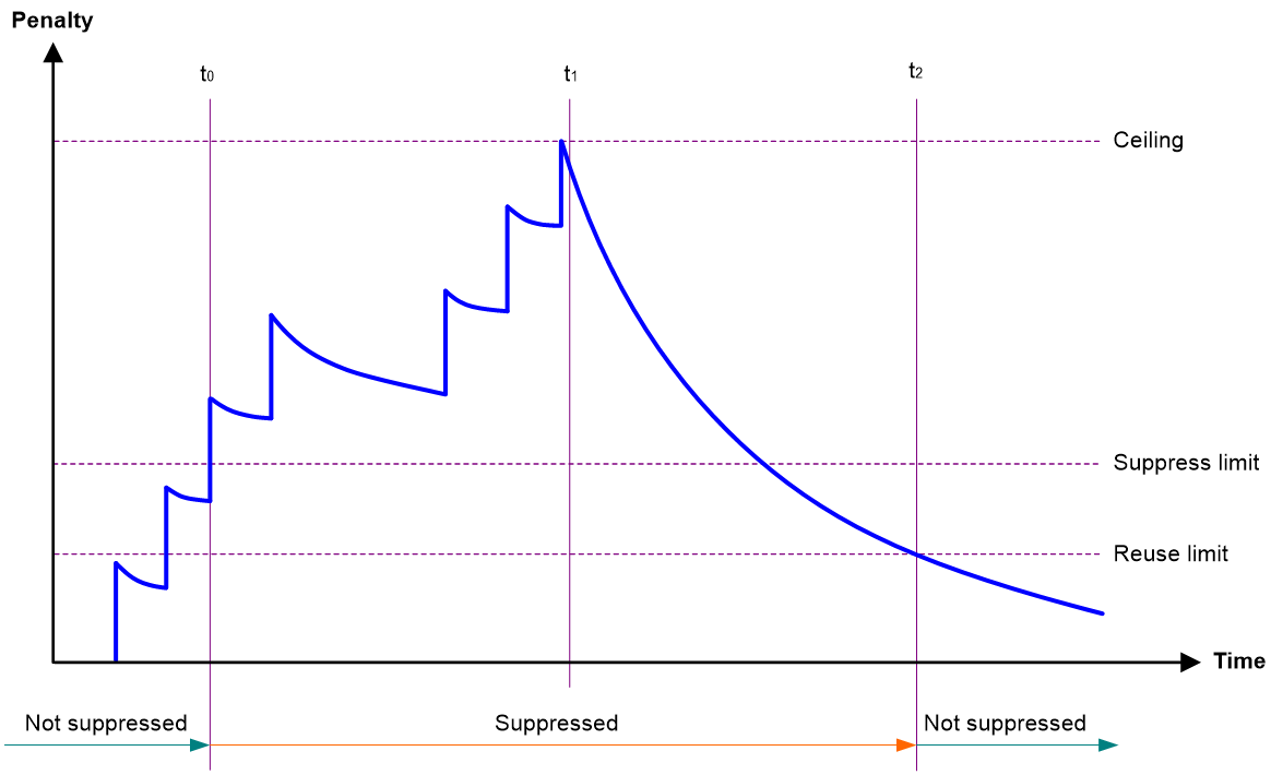
· Penalty—The interface has an initial penalty of 0. When the interface flaps, the penalty increases by 1000 for each down event until the ceiling is reached. It does not increase for up events. When the interface stops flapping, the penalty decreases by half each time the half-life timer expires until the penalty drops to the reuse threshold.
· Ceiling—The penalty stops increasing when it reaches the ceiling.
· Suppress-limit—The accumulated penalty that triggers the device to dampen the interface. In dampened state, the interface does not report its state changes to the CPU. For state change events, the interface only generates SNMP traps and log messages.
· Reuse-limit—When the accumulated penalty decreases to this reuse threshold, the interface is not dampened. Interface state changes are reported to the upper layers. For each state change, the system also generates an SNMP trap and log message.
· Decay—The amount of time (in seconds) after which a penalty is decreased.
· Max-suppress-time—The maximum amount of time the interface can be dampened. If the penalty is still higher than the reuse threshold when this timer expires, the penalty stops increasing for down events. The penalty starts to decrease until it drops below the reuse threshold.
When configuring the dampening command, follow these rules to set the values mentioned above:
· The ceiling is equal to 2(Max-suppress-time/Decay) × reuse-limit. It is not user configurable.
· The configured suppress limit is lower than or equal to the ceiling.
· The ceiling is lower than or equal to the maximum suppress limit supported.
Figure 1 shows the change rule of the penalty value. The lines t0 and t2 indicate the start time and end time of the suppression, respectively. The period from t0 to t2 indicates the suppression period, t0 to t1 indicates the max-suppress-time, and t1 to t2 indicates the complete decay period.
Figure 1 Change rule of the penalty value
Restrictions and guidelines
The dampening and port link-flap protect enable commands are mutually exclusive on an Ethernet interface.
The dampening command does not take effect on the administratively down events. When you execute the shutdown command, the penalty restores to 0, and the interface reports the down event to the upper-layer protocols.
As a best practice, do not enable the dampening feature on an interface with MSTP enabled.
Procedure
40. Enter system view.
system-view
41. Enter Ethernet interface view.
interface interface-type interface-number
42. Enable dampening on the interface.
dampening [ half-life reuse suppress max-suppress-time ]
By default, interface dampening is disabled on Ethernet interfaces.
Enabling link flapping protection on an interface
About this task
Link flapping on an interface changes network topology and increases the system overhead. For example, in an active/standby link scenario, when interface status on the active link changes between UP and DOWN, traffic switches between active and standby links. To solve this problem, configure this feature on the interface.
With this feature enabled on an interface, when the interface goes down, the system enables link flapping detection. During the link flapping detection interval, if the number of detected flaps reaches or exceeds the link flapping detection threshold, the system shuts down the interface.
Restrictions and guidelines
This feature takes effect only if it is configured in both the system view and interface view.
IRF system stability might be affected by IRF physical link flapping. For IRF system stability, this feature is enabled by default on IRF physical interfaces and the enabling status of this feature is not affected by the status of global link flapping protection. When the number of flaps detected on an IRF physical interface exceeds the threshold within the detection interval, the device outputs a log rather than shuts down the IRF physical interface.
The dampening and port link-flap protect enable commands are mutually exclusive on an Ethernet interface.
To bring up an interface that has been shut down by link flapping protection, execute the undo shutdown command.
In the display interface command output, the Link-Flap DOWN value of the Current state field indicates that the interface has been shut down by link flapping protection.
Procedure
43. Enter system view.
system-view
44. Enable link flapping protection globally.
link-flap protect enable
By default, link flapping protection is disabled globally.
45. Enter Ethernet interface view.
interface interface-type interface-number
46. Enable link flapping protection on the Ethernet interface.
port link-flap protect enable [ interval interval | threshold threshold ] *
By default, link flapping protection is disabled on an Ethernet interface.
Configuring FEC
About this task
The forward error correction (FEC) feature corrects packet errors to improve transmission quality. It attaches correction information to a packet at the sending end, and corrects error codes generated during transmission at the receiving end based on the correction information. You can set the FEC mode as needed.
Restrictions and guidelines
This feature is supported only on 25-GE and 100-GE interfaces.
The current Ethernet interface is operating at 10 Gbps. If you configure FEC on the interface, interface flapping will occur.
Make sure you set the same FEC mode for both interfaces of a link.
Procedure
47. Enter system view.
system-view
48. Enter Ethernet interface view.
interface interface-type interface-number
49. Set the FEC mode of the Ethernet interface.
port fec mode { auto | base-r | none | rs-fec }
By default, the FEC mode of an Ethernet interface is autonegotiated.
The base-r keyword is not supported on 100-GE interfaces.
Configuring link compensation
About this task
As the signal transmission rate or frequency increases, high frequency components in signals attenuate more severely. For signal transmission performance, common signal compensation technologies such as pre-emphasis and equalization are introduced. Pre-emphasis amplifies high frequency components but increases the probability of crosstalk. Equalization is introduced to filter out high frequency crosstalk on the receiving end.
Link compensation enables the sending and receiving ends to exchange pre-emphasis and equalization parameters through frames. This feature improves the performance of pre-emphasis and equalization.
Restrictions and guidelines
This feature is supported only on 25-GE connected through copper cables.
You must enable or disable link compensation on both interfaces of a link.
Procedure
50. Enter system view.
system-view
51. Enter Ethernet interface view.
interface interface-type interface-number
52. Configure link compensation on the interface.
port training enable
By default, link compensation is disabled on an interface.
Configuring generic flow control on an Ethernet interface
About this task
To avoid dropping packets on a link, you can enable generic flow control at both ends of the link. When traffic congestion occurs at the receiving end, the receiving end sends a flow control (Pause) frame to ask the sending end to suspend sending packets. Generic flow control includes the following types:
· TxRx-mode generic flow control—Enabled by using the flow-control command. With TxRx-mode generic flow control enabled, an interface can both send and receive flow control frames:
¡ When congestion occurs, the interface sends a flow control frame to its peer.
¡ When the interface receives a flow control frame from its peer, it suspends sending packets to its peer.
· Rx-mode generic flow control—Enabled by using the flow-control receive enable command. With Rx-mode generic flow control enabled, an interface can receive flow control frames, but it cannot send flow control frames:
¡ When congestion occurs, the interface cannot send flow control frames to its peer.
¡ When the interface receives a flow control frame from its peer, it suspends sending packets to its peer.
To handle unidirectional traffic congestion on a link, configure the flow-control receive enable command at one end and the flow-control command at the other end. To enable both ends of a link to handle traffic congestion, configure the flow-control command at both ends.
Restrictions and guidelines
This feature is not supported on interfaces on a MIC subcard in a CSPEX-1104-E, CSPEX-2304X-G, CSPEX-2304X-LG, or SPEX-1204 card.
Procedure
53. Enter system view.
system-view
54. Enter Ethernet interface view.
interface interface-type interface-number
55. Enable generic flow control.
¡ Enable TxRx-mode generic flow control:
flow-control
¡ Enable Rx-mode generic flow control:
flow-control receive enable
By default, generic flow control is disabled on an Ethernet interface.
Configuring PFC on an inner interface
About this task
An inner interface is the inner Ethernet interface through which a card communicates with the device, and is invisible for users.
With PFC enabled on an inner interface, when the traffic from an LPU to a switching fabric module is congested, the inner interface on the switching fabric module sends PFC pause frames to the inner interface on the LPU to notify the LPU to stop sending packets to the switching fabric module. When congestion is eliminated, the inner interface on the switching fabric module notifies the LPU to continue to send packets to the switching fabric module. This rule also applies to the traffic from a switching fabric module to an LPU.
When congestion occurs in the network, the local device notifies the peer to stop sending packets carrying the specified 802.1p priority if all of the following conditions exist:
· Both the local inner interface and the remote inner interface have priority-based flow control (PFC) enabled.
· Both the local inner interface and the remote inner interface have the priority-flow-control inner-port no-drop command configured.
· The specified 802.1p priority is in the 802.1p priority list specified by the dot1p-list argument.
· The local inner interface receives a packet carrying the specified 802.1p priority.
For more information about 802.1p priorities, see ACL and QoS Configuration Guide.
Make sure all interfaces that a data flow passes through have the same PFC configuration.
Table 1 PFC configurations and negotiation results
|
Local (right) Peer (below) |
enable |
auto |
Default |
|
enable |
Enabled |
Enabled. |
Disabled |
|
auto |
Enabled |
· Enabled if negotiation succeeds. · Disabled if negotiation fails. |
Disabled |
|
Default |
Disabled |
Disabled. |
Disabled |
Restrictions and guidelines
On a SR8800-X device, this feature is supported when the device is only installed with type B or type D switching fabric modules.
On a SR8800-X-S devices, this feature is supported only when the device is only installed with SR07SRPUA1 and SR07SRPUD3 MPUs.
In IRF mode, this feature is supported only when the incoming interface and outgoing interface are on the same IRF member device.
Procedure
56. Enter system view.
system-view
57. Enable PFC on inner interfaces.
priority-flow-control inner-port { auto | enable }
By default, PFC is disabled on inner interfaces.
An inner interface is the inner Ethernet interface through which a card communicates with the device, and is invisible to users.
58. Enable PFC for 802.1p priorities on inner interfaces.
priority-flow-control inner-port no-drop dot1p dot1p-list
By default, PFC is disabled for all 802.1p priorities.
Setting the statistics polling interval
About this task
By setting the statistics polling interval, you can collect statistics of packets and analyze packets at the specified interval. Based on the interface traffic statistics, you can take traffic control measures promptly to avoid network congestion and service interruption.
· When network congestion is detected, you can set the statistics polling interval to be smaller than 300 seconds (30 seconds when congestion deteriorates). Then, check traffic distribution on interfaces within a short period of time. For data packets that cause congestion, take traffic control measures.
· When the network bandwidth is sufficient and services are operating normally, you can set the statistics polling interval to be greater than 300 seconds. Once traffic parameter anomalies occur, modify the statistics polling interval promptly so that you can observe the traffic parameter trend in real time.
To display the interface statistics collected in the last statistics polling interval, use the display interface command. To clear the interface statistics, use the reset counters interface command.
You can use this command in system view or interface view.
· In system view, the command takes effect on all interfaces.
· In interface view, the command takes effect only on the specified interface.
When the statistics polling interval uses the default setting in interface view, the setting in system view takes effect. When the command is executed in both system view and interface view, the setting in interface view takes priority.
Restrictions and guidelines for setting the statistics polling interval
As a best practice, use the default statistics polling interval in system view. A short statistics polling interval in system view might decrease the system performance and result in inaccurate statistics.
Setting the statistics polling interval in system view
59. Enter system view.
system-view
60. Set the statistics polling interval.
flow-interval interval
By default, the statistics polling interval is 300 seconds.
Setting the statistics polling interval in Ethernet interface view
61. Enter system view.
system-view
62. Enter Ethernet interface view.
interface interface-type interface-number
63. Set the statistics polling interval for the Ethernet interface.
flow-interval interval
By default, the statistics polling interval is 300 seconds on an interface.
Enabling interframe gap and preamble statistics in the traffic statistics
About this task
With the display interface command executed, the Last 300 seconds input rate or Last 300 seconds output rate field in the command output displays the average outbound or inbound traffic rate in the last 300 seconds.
By default, traffic rate = native frame length × packet count per second. Execute the traffic-statistic include-interframe command if you need the total traffic statistics, including the native frame length, interframe gap length and preamble length, for a specific time period. With this command executed, traffic rate = (native frame length + interframe gap length + preamble length) × packet count per second.
Procedure
64. Enter system view.
system-view
65. Enter Ethernet interface view.
interface interface-type interface-number
66. Enable interframe gap and preamble statistics in the traffic statistics.
traffic-statistic include-interframe
By default, interframe gap and preamble statistics are enabled in the traffic statistics.
Enabling loopback testing on an Ethernet interface
About this task
Perform this task to determine whether an Ethernet link works correctly.
Loopback testing includes the following types:
· Internal loopback testing—Tests the device where the Ethernet interface resides. The Ethernet interface sends outgoing packets back to the local device. If the device fails to receive the packets, the device fails.
· External loopback testing—Tests the inter-device link. The Ethernet interface sends incoming packets back to the remote device. If the remote device fails to receive the packets, the inter-device link fails.
Restrictions and guidelines
The internal keyword can be configured but does not take effect on the following interfaces:
· Interfaces on the CEPC-XP48RX card.
· Interfaces on the MIC-CP1L, MIC-QP1L, and MIC-XP2L-LAN subcards.
· The first interface on the MIC-XP5L subcard.
After the following interfaces are changed to GE interfaces by using the using gigabit command, they do not support the internal keyword:
· All interfaces on the MIC-XP2L, MIC-XP4L1, MIC-XP5L2, and MIC-XP20L subcards.
· The last four interfaces on the MIC-XP5L and MIC-XP5L1 subcards.
Interfaces on a MIC-XP10LF interface subcard support external loopback testing. When you perform external loopback testing on such interfaces, make sure the interfaces at both the local and peer ends are 10-GE interfaces.
After you enable this feature on an Ethernet interface, the interface does not forward data traffic.
The shutdown and loopback commands are mutually exclusive.
After you enable this feature on an Ethernet interface, the Ethernet interface switches to full duplex mode. After you disable this feature, the Ethernet interface restores to its duplex setting.
Procedure
67. Enter system view.
system-view
68. Enter Ethernet interface view.
interface interface-type interface-number
69. Enable loopback testing.
loopback { external | internal }
By default, loopback testing is disabled on an Ethernet interface.
Configuring interface alarm functions
About this task
With the interface alarm functions enabled, when the number of sent or received error packets or the input or output bandwidth usage on an interface in normal state within the specified interval exceeds the upper threshold, the interface generates an upper threshold exceeding alarm and enters the alarm state. When the number of sent or received error packets or the input or output bandwidth usage on an interface in the alarm state within the specified interval drops below the lower threshold, the interface generates a recovery alarm and restores to the normal state.
Restrictions and guidelines
You can configure the error packet alarm parameters in system view and interface view.
· The configuration in system view takes effect on all interfaces of the specified slot. The configuration in interface view takes effect only on the current interface.
· For an interface, the configuration in interface view takes priority, and the configuration in system view is used only when no configuration is made in interface view.
An interface that is shut down because of error packet alarms cannot automatically recover. To bring up the interface, execute the undo shutdown command on the interface.
Enabling interface alarm functions
70. Enter system view.
system-view
71. Enable alarm functions for the interface monitoring module.
snmp-agent trap enable ifmonitor [ crc-error | giant | input-buffer-drop | input-error | input-usage | output-buffer-drop | output-error | output-usage | runt ] *
By default, all alarm functions are enabled for interfaces.
Configuring CRC error packet alarm parameters
72. Enter system view.
system-view
73. Configure global CRC error packet alarm parameters.
In standalone mode:
ifmonitor crc-error slot slot-number [ cpu cpu-number ] high-threshold high-value low-threshold low-value interval interval [ shutdown ]
In IRF mode:
ifmonitor crc-error chassis chassis-number slot slot-number [ cpu cpu-number ] high-threshold high-value low-threshold low-value interval interval [ shutdown ]
By default, the upper threshold is 1000, the lower threshold is 100, and the statistics collection and comparison interval is 10 seconds for CRC error packets.
74. Enter Ethernet interface view.
interface interface-type interface-number
75. Configure CRC error packet alarm parameters for the interface.
port ifmonitor crc-error [ ratio ] high-threshold high-value low-threshold low-value interval interval [ shutdown ]
By default, an interface uses the global CRC error packet alarm parameters.
Configuring input error packet alarm parameters
76. Enter system view.
system-view
77. Configure global input error packet alarm parameters.
In standalone mode:
ifmonitor input-error slot slot-number [ cpu cpu-number ] high-threshold high-value low-threshold low-value interval interval [ shutdown ]
In IRF mode:
ifmonitor input-error chassis chassis-number slot slot-number [ cpu cpu-number ] high-threshold high-value low-threshold low-value interval interval [ shutdown ]
By default, the upper threshold is 1000, the lower threshold is 100, and the statistics collection and comparison interval is 10 seconds for input error packets.
78. Enter Ethernet interface view.
interface interface-type interface-number
79. Configure input error packet alarm parameters for the interface.
port ifmonitor input-error high-threshold high-value low-threshold low-value interval interval [ shutdown ]
By default, an interface uses the global input error packet alarm parameters.
Configuring output error packet alarm parameters
80. Enter system view.
system-view
81. Configure global output error packet alarm parameters.
In standalone mode:
ifmonitor output-error slot slot-number [ cpu cpu-number ] high-threshold high-value low-threshold low-value interval interval [ shutdown ]
In IRF mode:
ifmonitor output-error chassis chassis-number slot slot-number [ cpu cpu-number ] high-threshold high-value low-threshold low-value interval interval [ shutdown ]
By default, the upper threshold is 1000, the lower threshold is 100, and the statistics collection and comparison interval is 10 seconds for output error packets.
82. Enter Ethernet interface view.
interface interface-type interface-number
83. Configure output error packet alarm parameters.
port ifmonitor output-error high-threshold high-value low-threshold low-value interval interval [ shutdown ]
By default, an interface uses the global output error packet alarm parameters.
Configuring input bandwidth usage alarm parameters
84. Enter system view.
system-view
85. Configure global input bandwidth usage alarm parameters.
In standalone mode:
ifmonitor input-usage slot slot-number [ cpu cpu-number ] high-threshold high-value low-threshold low-value
In IRF mode:
ifmonitor input-usage chassis chassis-number slot slot-number [ cpu cpu-number ] high-threshold high-value low-threshold low-value
By default, the upper threshold is 90 and the lower threshold is 80 for input bandwidth usage alarms.
86. Enter Ethernet interface view.
interface interface-type interface-number
87. Configure input bandwidth usage alarm parameters.
port ifmonitor input-usage high-threshold high-value low-threshold low-value
By default, an interface uses the global input bandwidth usage alarm parameters.
Configuring output bandwidth usage alarm parameters
88. Enter system view.
system-view
89. Configure global output bandwidth usage alarm parameters.
In standalone mode:
ifmonitor output-usage slot slot-number [ cpu cpu-number ] high-threshold high-value low-threshold low-value
In IRF mode:
ifmonitor output-usage chassis chassis-number slot slot-number [ cpu cpu-number ] high-threshold high-value low-threshold low-value
By default, the upper threshold is 90 and the lower threshold is 80 for output bandwidth usage alarms.
90. Enter Ethernet interface view.
interface interface-type interface-number
91. Configure output bandwidth usage alarm parameters.
port ifmonitor output-usage high-threshold high-value low-threshold low-value
By default, an interface uses the global output bandwidth usage alarm parameters.
Configuring giant packet alarm parameters
92. Enter system view.
system-view
93. Configure global giant packet alarm parameters.
In standalone mode:
ifmonitor giant slot slot-number [ cpu cpu-number ] high-threshold high-value low-threshold low-value interval interval [ shutdown ]
In IRF mode:
ifmonitor giant chassis chassis-number slot slot-number [ cpu cpu-number ] high-threshold high-value low-threshold low-value interval interval [ shutdown ]
By default, the upper threshold is 1000, the lower threshold is 100, and the statistics collection and comparison interval is 10 seconds for giant packets.
94. Enter Ethernet interface view.
interface interface-type interface-number
95. Configure giant packet alarm parameters for the interface.
port ifmonitor giant high-threshold high-value low-threshold low-value interval interval [ shutdown ]
By default, an interface uses the global giant packet alarm parameters.
Configuring runt packet alarm parameters
96. Enter system view.
system-view
97. Configure global runt packet alarm parameters.
In standalone mode:
ifmonitor runt slot slot-number [ cpu cpu-number ] high-threshold high-value low-threshold low-value interval interval [ shutdown ]
In IRF mode:
ifmonitor runt chassis chassis-number slot slot-number [ cpu cpu-number ] high-threshold high-value low-threshold low-value interval interval [ shutdown ]
By default, the upper threshold is 1000, the lower threshold is 100, and the statistics collection and comparison interval is 10 seconds for runt packets.
98. Enter Ethernet interface view.
interface interface-type interface-number
99. Configure runt packet alarm parameters for the interface.
port ifmonitor runt high-threshold high-value low-threshold low-value interval interval [ shutdown ]
By default, an interface uses the global runt packet alarm parameters.
Configuring packet-drop alarm parameters for the ingress buffer
100. Enter system view.
system-view
101. Configure packet-drop alarm parameters for the ingress buffer globally.
In standalone mode:
ifmonitor input-buffer-drop slot slot-number[ cpu cpu-number ] high-threshold high-value low-threshold low-value interval interval [ shutdown ]
In IRF mode:
ifmonitor input-buffer-drop chassis chassis-number slot slot-number [ cpu cpu-number ] high-threshold high-value low-threshold low-value interval interval [ shutdown ]
By default, the upper threshold is 1000, the lower threshold is 100, and the statistics collection and comparison interval is 10 seconds.
102. Enter Ethernet interface view.
interface interface-type interface-number
103. Configure packet-drop alarm parameters for the ingress buffer.
port ifmonitor input-buffer-drop high-threshold high-value low-threshold low-value interval interval [ shutdown ]
By default, an interface uses the packet-drop alarm parameters globally configured for the ingress buffer.
Configuring packet-drop alarm parameters for the egress buffer
104. Enter system view.
system-view
105. Configure packet-drop alarm parameters for the egress buffer globally.
In standalone mode:
ifmonitor output-buffer-drop slot slot-number [ cpu cpu-number ] high-threshold high-value low-threshold low-value interval interval [ shutdown ]
In IRF mode:
ifmonitor output-buffer-drop chassis chassis-number slot slot-number [ cpu cpu-number ] high-threshold high-value low-threshold low-value interval interval [ shutdown ]
By default, the upper threshold is 1000, the lower threshold is 100, and the statistics collection and comparison interval is 10 seconds.
106. Enter Ethernet interface view.
interface interface-type interface-number
107. Configure packet-drop alarm parameters for the egress buffer.
port ifmonitor output-buffer-drop high-threshold high-value low-threshold low-value interval interval [ shutdown ]
By default, an interface uses the packet-drop alarm parameters globally configured for the egress buffer.
Configuring SNMP notifications for cards
About this task
With this feature configured for a card, the card triggers an SNMP notification when the number of dropped packets received within the specified time exceeds the upper threshold. When the number of dropped packets received within the specified time drops below the lower threshold, the card triggers a recovery notification and restores to normal state.
Enabling SNMP notifications for cards
108. Enter system view.
system-view
109. Enable SNMP notifications for cards.
snmp-agent trap enable slot-monitor [ packet-drop ] *
By default, SNMP notifications are enabled for cards.
Configuring packet-drop alarm parameters for all cards
110. Enter system view.
system-view
111. Configure packet-drop alarm parameters for all cards.
slot-monitor packet-drop high-threshold high-threshold-value low-threshold low-threshold-value interval interval [ shutdown | reboot ]
By default, the upper threshold is 1000000, the lower threshold is 100, and the statistics collection and comparison interval is 30 seconds.
Configuring packet-drop alarm parameters for a card
112. Enter system view.
system-view
113. Configure packet-drop alarm parameters for a card.
In standalone mode:
slot-monitor packet-drop slot slot-number high-threshold high-threshold-value low-threshold low-threshold-value interval interval [ shutdown | reboot ]
In IRF mode:
slot-monitor packet-drop chassis chassis-number slot slot-number high-threshold high-threshold-value low-threshold low-threshold-value interval interval [ shutdown | reboot ]
By default, the upper threshold is 1000000, the lower threshold is 100, and the statistics collection and comparison interval is 30 seconds.
Displaying the operating status and information of an interface
About this task
In interface view, to quickly view the operating status or packet statistics of the interface, execute this command.
For an interface, the output from the display this interface command in interface view is the same as the output from the display interface interface-type interface-number command in any view.
Procedure
114. Enter system view.
system-view
115. Enter Ethernet interface view.
interface interface-type interface-number
116. Display the operating status and information of an interface.
display this interface
Shutting down all physical interfaces
About this task
This feature allows you to shut down all physical interfaces except the management Ethernet interfaces and IRF physical interfaces on a device. Physical interfaces shut down by using this command are in ADM state.
Restrictions and guidelines
To shut down all physical interfaces or the specified interface, execute the shutdown all-physical-interfaces command in system view or execute the shutdown command in interface view.
To bring up a shutdown interface, execute the undo shutdown all-physical-interfaces command in system view and execute the undo shutdown command in interface view.
If you execute this command with the include irf-physical-interface keyword multiple times, this command shuts down all physical interfaces except the management Ethernet interfaces on the device.
Procedure
117. Enter system view.
system-view
118. Shut down all physical interfaces.
shutdown all-physical-interfaces [ include irf-physical-interface ]
By default, all physical interfaces are up.
Restoring the default settings for an interface
Restrictions and guidelines
|
|
CAUTION: This feature might interrupt ongoing network services. Make sure you are fully aware of the impacts of this feature when you use it in a live network. |
This feature might fail to restore the default settings for some commands because of command dependencies or system restrictions. You can use the display this command in interface view to check for these commands and perform their undo forms or follow the command reference to restore their default settings. If your restoration attempt still fails, follow the error message to resolve the problem.
Procedure
119. Enter system view.
system-view
120. Enter Ethernet interface view or Ethernet subinterface view.
interface interface-type { interface-number | interface-number.subnumber }
121. Restore the default settings for the interface.
default
Configuring a Layer 3 Ethernet interface
Enabling Layer 2 forwarding on an interface
About this task
By default, a Layer 3 interface only performs Layer 3 forwarding. This command enables a Layer 3 Ethernet interface to transmit VLAN tagged packets by creating a virtual Layer 2 Ethernet interface for that Layer 3 Ethernet interface. You can configure VLAN settings on the virtual Layer 2 Ethernet interface.
This feature shuts down the data link layer of a Layer 3 Ethernet interface. While the Layer 3 Ethernet interface cannot provide Layer 3 services, its subinterfaces can terminate VLANs and continue to provide Layer 3 services.
Restrictions and guidelines
This feature is available only for the following cards:
|
Card category |
Cards |
|
CEPC |
CEPC-XP4LX, CEPC-XP24LX, CEPC-XP48RX, CEPC-CP4RX, CEPC-CP4RX-L, CEPC-CQ8L, CEPC-CQ16L1, CEPC-DQ2L1-G |
|
CSPEX |
CSPEX-1304X, CSPEX-1304S, CSPEX-1404X, CSPEX-1404S, CSPEX-1502X, CSPEX-1504X, CSPEX-1504S, CSPEX-1602X, CSPEX-1804X, CSPEX-1512X, CSPEX-1612X, CSPEX-1812X, CSPEX-1802XB, CSPEX-1802X, CSPEX-1812X-E, CSPEX-2304X-G, CSPEX-2304X-LG, CSPEX-2612X-E |
|
SPE |
RX-SPE200, RX-SPE200-E |
After you execute this command, port mirroring configured on a Layer 3 Ethernet interface takes effect on the newly generated virtual Layer 2 interfaces. For more information about port mirroring, see Network Management and Monitoring Configuration Guide.
After you execute this command, outbound traffic shaping, rate limiting, WRED, and the queue scheduling profile configured on a Layer 3 Ethernet interface take effect on the newly generated virtual Layer 2 interfaces. For more information about traffic shaping, rate limiting, WRED, and the queue scheduling profile, see ACL and QoS Configuration Guide.
After this command is executed, the outbound rate limiting function and the queue scheduling profile configured through the user profile applied to an interface by using the qos apply user-profile command take effect on the newly generated virtual Layer 2 interface. For more information about the outbound rate limiting function and the queue scheduling profile configured through the user profile applied to an interface by using the qos apply user-profile command, see BRAS Services Configuration Guide.
This feature is not supported on a Layer 3 Ethernet interface that has been assigned to a Layer 3 aggregate interface.
You cannot enable this feature on a main interface whose subinterfaces terminate the outermost VLAN ID 1.
The outermost VLAN IDs terminated by subinterfaces of a main interface cannot contain the PVID of and VLAN IDs permitted by the virtual Layer 2 interface created for the main interface.
On a Layer 3 Ethernet interface with this feature enabled, you cannot perform the following tasks:
· Splitting an interface and switching the interface type.
· Switching the interface mode between bridge and route.
· Binding the interface to an IRF port as an IRF physical interface.
· Assigning an interface to a Layer 3 aggregation group.
Procedure
122. Enter system view.
system-view
123. Enter Layer 3 Ethernet interface view.
interface interface-type interface-number
124. Enable Layer 2 forwarding on the Layer 3 Ethernet interface.
bridge-forwarding enable
By default, Layer 2 forwarding is disabled on a Layer 3 Ethernet interface.
|
|
CAUTION: Configuring this feature on a Layer 3 Ethernet interface deletes all physical layer settings (if any) on the interface. Use this command as needed. |
125. Return to system view.
quit
126. Enter virtual Layer 2 Ethernet interface view.
interface virtual-bridge-port interface-number
127. Configure a description for the interface.
description text
By default, the description of an interface is Interface name Interface, for example, Virtual-Bridge-Port3/1/1 Interface.
Setting the MTU for an Ethernet interface or subinterface
About this task
The maximum transmission unit (MTU) determines the maximum number of bytes in a single IP packet that can be sent. The length of an IP packet refers to the number of bytes starting from the IP header to the payload.
When the IP layer receives an IP data packet to be sent, the IP layer determines the local destination interface of the packet and obtains the MTU of the interface. The IP layer compares the MTU with the length of the data packet to be sent. If the length is greater than the MTU, the IP layer fragments the packet. The length of a fragment can be smaller than or equal to the MTU to ensure that big packets are not lost on the network.
As a best practice, use the default MTU. When the packet length or the packet receiver changes, you can adjust the MTU as needed. When configuring the MTU, follow these restrictions and guidelines:
· If the configured MTU is small but the packet length is large, the following events might occur:
¡ Packets will be dropped when they are forwarded by hardware.
¡ Packets will be fragmented into too many fragments when packets are forwarded through the CPUs, which affects normal data transmission.
· If the configured MTU is too large, the MTU will exceed the receiving capabilities of the receiver or a device along the transmission path. As a result, packets will be fragmented or even dropped, which increases the network transmission load and affects data transmission.
Restrictions and guidelines
The MTU of an Ethernet interface or subinterface affects the fragmentation and reassembly of IP packets on the interface. Typically, you do not need to modify the MTU of an interface.
The mtu size command executed in main interface view takes effect only on the main interface. The mtu size command executed in subinterface view takes effect only on the subinterface.
The mtu size spread command executed in main interface view can modify the MTU for both the main interface and its subinterfaces. However, the MTU separately configured for a subinterface takes priority.
· For interfaces on MIC subcards in a CSPEX-1104-E or SPEX-1204 card, the value range is 46 to 2980 bytes.
· For interfaces on PIC-PS2G4L or PIC-TCP8L subcards in a SPEX-1204 card, the value range is 46 to 2000 bytes.
· For interfaces on PIC-GP10L subcards in a SPEX-1204 card, the value range is 46 to 3000 bytes.
· For interfaces on other PIC subcards in a SPEX-1204 card, the value range is 46 to 9100 bytes.
The outgoing interface uses the MTU of 1280 bytes if its MTU is smaller than 1280 bytes and the incoming interface is on the specified cards. As a best practice, set the MTU of the outgoing interface to a value greater than 1280 bytes when the device is installed with the cards mentioned above.
Procedure
128. Enter system view.
system-view
129. Enter Ethernet interface or subinterface view.
interface interface-type { interface-number | interface-number.subnumber }
130. Set the MTU.
¡ Separately set the MTU for the Ethernet interface or subinterface.
mtu size
¡ Set the MTU for the main interface and its subinterfaces.
mtu size spread
Subinterfaces do not support this command.
The default setting is 1500 bytes.
Setting the MAC address of an Ethernet interface
About this task
In an active/standby link network, you can configure the same MAC address for access interfaces of the active link and standby link on different devices. Then, when an active/standby link switchover occurs, the packet loss duration is reduced.
Restrictions and guidelines
This feature is available only for the following cards:
|
Card category |
Cards |
|
CEPC |
CEPC-CP4RX, CEPC-CP4RXA, CEPC-CP4RX-L, CEPC-CQ8LA, CEPC-CQ8L, CEPC-XP4LX, CEPC-XP24LX, CEPC-XP48RX |
|
CSPEX |
CSPEX-1304X, CSPEX-1404X, CSPEX-1502X, CSPEX-1502XA, CSPEX-1504X, CSPEX-1504XA, CSPEX-1602X, CSPEX-1602XA, CSPEX-1802X, CSPEX-1802XA, CSPEX-1804X, CSPEX-1512X, CSPEX-1612X, CSPEX-1812X, CSPEX-1812X-E, CSPEX-2304X-G, CSPEX-2304X-LG, CSPEX-2304X-G |
|
SPE |
RX-SPE200-E |
In standard mode, the MAC address range supported is 000f-e2ff-8000 to 000f-e2ff-80ff for Layer 3 aggregate interfaces with member ports in the following cards:
|
Card category |
Cards |
|
CEPC |
CEPC-CP4RX, CEPC-CP4RXA, CEPC-CP4RX-L, CEPC-CQ8LA, CEPC-XP4LX, CEPC-XP24LX, CEPC-XP48RX |
|
CSPEX |
CSPEX-1304X, CSPEX-1404X, CSPEX-1502X, CSPEX-1502XA, CSPEX-1504X, CSPEX-1504XA, CSPEX-1602X, CSPEX-1602XA, CSPEX-1802XA, CSPEX-1804X, CSPEX-1512X, CSPEX-1612X, CSPEX-1812X, CSPEX-2304X-G, CSPEX-2304X-LG, CSPEX-2304X-G |
|
SPE |
RX-SPE200-E |
You cannot use this command to modify the MAC address for a main interface or subinterface with BRAS users online.
You cannot set a MAC address for a subinterface. A subinterface uses the MAC address of the main interface. All subinterfaces of a main interface share the same MAC address.
Procedure
131. Enter system view.
system-view
132. Enter Ethernet interface view.
interface interface-type interface-number
133. Set the MAC address of the Ethernet interface or subinterface.
mac-address mac-address
By default, the MAC address of a Layer 3 Ethernet interface is assigned by the device.
As a best practice, do not set a MAC address in the VRRP-reserved MAC address range for a Layer 3 Ethernet interface.
Changing the interface type
About this task
You can change the interface type between POS and GigabitEthernet.
Restrictions and guidelines
Only interfaces on MIC-TCP8L and PIC-TCP8L subcards support this feature.
Changing a Layer 3 GigabitEthernet interface to a standard POS interface
134. Enter system view.
system-view
135. Enter Layer 3 GigabitEthernet interface view.
interface gigabitethernet interface-number
136. Change the interface to a standard POS interface.
port-type switch pos
|
|
CAUTION: After the type of an interface is changed, the system deletes the original interface and creates a new interface that is numbered the same as the original interface. All the other commands are restored to the default on the new interface. |
Changing a standard POS interface to a Layer 3 GigabitEthernet interface
137. Enter system view.
system-view
138. Enter standard POS interface view.
interface pos interface-number
139. Change the interface to a Layer 3 GigabitEthernet interface.
port-type switch gigabitethernet
|
|
CAUTION: After the type of an interface is changed, the system deletes the original interface and creates a new interface that is numbered the same as the original interface. All the other commands are restored to the default on the new interface. |
Enabling packet statistics collection on a Layer 3 Ethernet subinterface
About this task
This feature is resource intensive. The system becomes busy and the CPU usage increases when you enable this feature on a large number of Ethernet subinterfaces or set a shorter interval by using the flow-interval command.
Procedure
140. Enter system view.
system-view
141. Enter Layer 3 Ethernet subinterface view.
interface interface-type interface-number.subnumber
142. Enable packet statistics collection on the Layer 3 Ethernet subinterface.
traffic-statistic enable
By default, packet statistics collection is disabled on a Layer 3 Ethernet subinterface.
143. (Optional.) Display the subinterface traffic statistics.
display interface
display counters
The Input and Output fields in the display interface command output display the subinterface traffic statistics.
Display and maintenance commands for an Ethernet interface or subinterface
Execute display commands in any view and reset commands in user view.
|
Task |
Command |
|
Display interface traffic statistics. |
display counters { inbound | outbound } interface [ interface-type [ interface-number | interface-number.subnumber ] ] [ description ] |
|
Display traffic rate statistics of interfaces in up state over the last statistics polling interval. |
display counters rate { inbound | outbound } interface [ interface-type [ interface-number | interface-number.subnumber ] ] [ description ] |
|
Display the Ethernet module statistics. |
In standalone mode: display ethernet statistics slot slot-number [ cpu cpu-number ] In IRF mode: display ethernet statistics chassis chassis-number slot slot-number [ cpu cpu-number ] |
|
Display the SNMP interface index constancy configuration information. |
display ifindex-constant configuration |
|
Display the interface name-constant interface index mappings. |
display ifindex-constant map [ file filename ] |
|
Display the operational and status information of the specified interfaces. |
display interface [ interface-type [ interface-number | interface-number.subnumber ] ] [ brief [ description | down ] ] |
|
Display the status and packet statistics of interfaces. |
display interface [ interface-type [ interface-number | interface-number.subnumber ] ] link-info [ down | up ] [ description ] [ main ] [ verbose ] |
|
Display the physical attributes of an interface. |
display interface [ interface-type [ interface-number ] ] phy-option |
|
Display information about link flapping protection on an interface. |
display link-flap protection [ interface interface-type [ interface-number ] ] |
|
Display the link state change statistics of interfaces. |
display link-state-change statistics interface [ interface-type [ interface-number ] |
|
Display operating status and information of all interfaces except subinterfaces. |
display interface [ interface-type ] [ brief [ description | down ] ] main |
|
Display information about dropped packets on the specified cards. |
In standalone mode: display packet-drop slot [ slot-number ] In IRF mode: display packet-drop chassis [ chassis-number [ slot slot-number ] ] |
|
Display alarm information for cards. |
display slot-monitor slot slot-number In IRF mode: display slot-monitor chassis chassis-number slot slot-number |
|
Clear interface or subinterface statistics. |
reset counters interface [ interface-type [ interface-number | interface-number.subnumber ] ] |
|
Clear interface or subinterface statistics on MIB. |
reset counters mib interface [ interface-type [ interface-number | interface-number.subnumber ] ] |
|
Clear cards statistics and interface statistics on cards. |
In standalone mode: reset counters slot [ slot-number ] In IRF mode: reset counters chassis [ chassis-number [ slot slot-number ] ] |
|
Clear the Ethernet module statistics. |
In standalone mode: reset ethernet statistics [ slot slot-number [ cpu cpu-number ] ] In IRF mode: reset ethernet statistics [ chassis chassis-number slot slot-number [ cpu cpu-number ] ] |
|
Clear the interface name-constant interface index mappings. |
reset ifindex-constant map |
|
Clear the link state change statistics of interfaces. |
reset link-state-change statistics interface [ interface-type [ interface-number ] |
|
Clear statistics about dropped packets on the specified interfaces. |
reset packet-drop interface [ interface-type [ interface-number ] ] |
