- Table of Contents
- Related Documents
-
| Title | Size | Download |
|---|---|---|
| 02-QoS configuration | 380.46 KB |
Contents
QoS processing flow in a device
Restrictions and guidelines for applying a QoS policy
Applying the QoS policy to an interface
Applying the QoS policy to a control plane
Applying the QoS policy in control-plane management view
Applying the QoS policy to original packets steered to an SRv6 TE policy
Setting the QoS policy-based traffic rate statistics collection period for an interface
Enabling SNMP notifications for QoS
Display and maintenance commands for QoS policies
Configuring traffic policing, GTS, and rate limit
About traffic policing, GTS, and rate limit
Traffic evaluation and token buckets
Traffic policing configuration approaches
Configuring traffic policing by using the MQC approach
Configuring CAR-list-based static traffic policing
Configuring ACL-based traffic policing
Configuring traffic policing for all traffic
Hardware compatibility with GTS
Configuring GTS by using the MQC approach
Configuring GTS for all traffic
Hardware compatibility with rate limit
Configuring the rate limit for an interface
Including the physical layer header in calculating the packet length for rate limiting
Display and maintenance commands for traffic policing, GTS, and rate limit
Restrictions and guidelines: Traffic filtering configuration
Appendix B Introduction to packet precedence
QoS overview
In data communications, Quality of Service (QoS) provides differentiated service guarantees for diversified traffic in terms of bandwidth, delay, jitter, and drop rate, all of which can affect QoS.
QoS manages network resources and prioritizes traffic to balance system resources.
The following section describes typical QoS service models and widely used QoS techniques.
QoS service models
This section describes several typical QoS service models.
Best-effort service model
The best-effort model is a single-service model. The best-effort model is not as reliable as other models and does not guarantee delay-free delivery.
The best-effort service model is the default model for the Internet and applies to most network applications. It uses the First In First Out (FIFO) queuing mechanism.
DiffServ model
The differentiated service (DiffServ) model is a multiple-service model that can meet diverse QoS requirements. It is easy to implement and extend. DiffServ does not signal the network to reserve resources before sending data, as IntServ does.
QoS techniques in a network
The QoS techniques include the following features:
· Traffic classification.
· Traffic policing.
· Traffic shaping.
· Rate limit.
· Congestion management.
· Congestion avoidance.
The following section briefly introduces these QoS techniques.
All QoS techniques in this document are based on the DiffServ model.
Figure 1 Position of the QoS techniques in a network
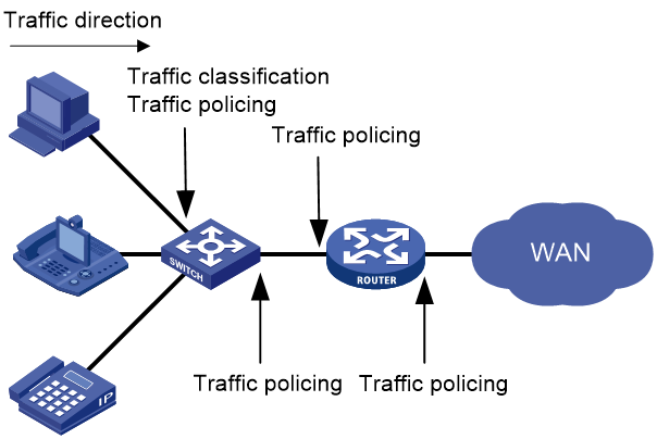
As shown in Figure 1, traffic classification, traffic shaping, traffic policing, congestion management, and congestion avoidance mainly implement the following functions:
· Traffic classification—Uses match criteria to assign packets with the same characteristics to a traffic class. Based on traffic classes, you can provide differentiated services.
· Traffic policing—Polices flows and imposes penalties to prevent aggressive use of network resources. You can apply traffic policing to both incoming and outgoing traffic of a port.
· Traffic shaping—Adapts the output rate of traffic to the network resources available on the downstream device to eliminate packet drops. Traffic shaping usually applies to the outgoing traffic of a port.
· Congestion management—Provides a resource scheduling policy to determine the packet forwarding sequence when congestion occurs. Congestion management usually applies to the outgoing traffic of a port.
· Congestion avoidance—Monitors the network resource usage. It is usually applied to the outgoing traffic of a port. When congestion worsens, congestion avoidance reduces the queue length by dropping packets.
QoS processing flow in a device
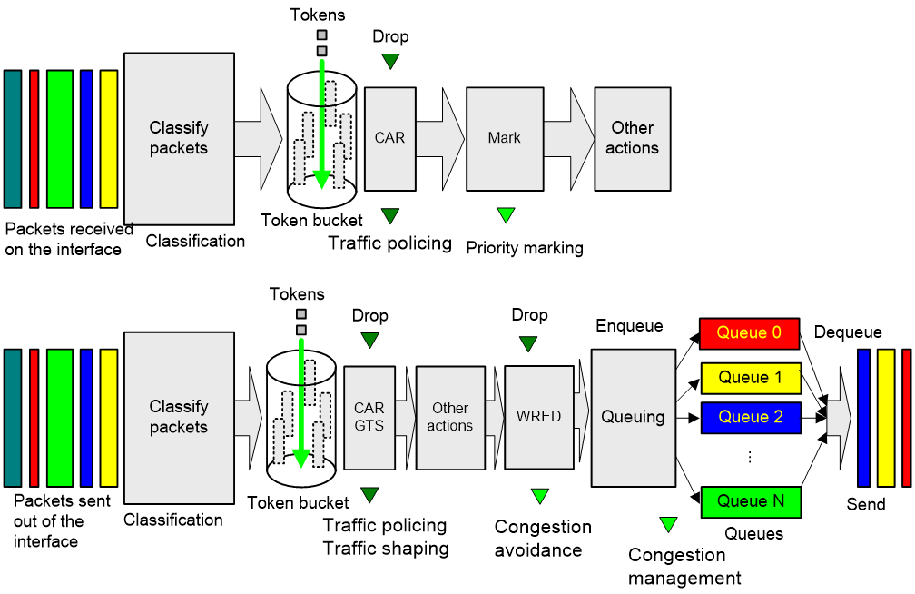
Figure 2 briefly describes how the QoS module processes traffic.
1. Traffic classifier identifies and classifies traffic for subsequent QoS actions.
2. The QoS module takes various QoS actions on classified traffic as configured, depending on the traffic processing phase and network status. For example, you can configure the QoS module to perform the following operations:
¡ Traffic policing for incoming traffic.
¡ Traffic shaping for outgoing traffic.
¡ Congestion avoidance before congestion occurs.
¡ Congestion management when congestion occurs.
QoS configuration approaches
You can configure QoS by using the MQC approach or non-MQC approach.
In the modular QoS configuration (MQC) approach, you configure QoS service parameters by using QoS policies. A QoS policy defines QoS actions to take on different classes of traffic and can be applied to an object (such as an interface) to control traffic.
In the non-MQC approach, you configure QoS service parameters without using a QoS policy.
Some features support both approaches, but some support only one.
Configuring a QoS policy
About QoS policies
A QoS policy has the following components:
· Traffic class—Defines criteria to match packets.
· Traffic behavior—Defines QoS actions to take on matching packets.
By associating a traffic class with a traffic behavior, a QoS policy can perform the QoS actions on matching packets.
A QoS policy can have multiple class-behavior associations.
QoS policy tasks at a glance
To configure a QoS policy, perform the following tasks:
2. Defining a traffic behavior
4. (Optional.) Configuring policy nesting
¡ Applying the QoS policy to an interface
¡ Applying the QoS policy to a control plane
¡ Applying the QoS policy in control-plane management view
¡ Applying the QoS policy to original packets steered to an SRv6 TE policy
6. (Optional.) Setting the QoS policy-based traffic rate statistics collection period for an interface
7. (Optional.) Enabling SNMP notifications for QoS
Defining a traffic class
1. Enter system view.
system-view
2. Create a traffic class and enter traffic class view.
traffic classifier classifier-name [ operator { and | or } ]
3. Configure a match criterion.
if-match [ not ] match-criteria
By default, no match criterion is configured.
For more information, see the if-match command in ACL and QoS Command Reference.
Defining a traffic behavior
1. Enter system view.
system-view
2. Create a traffic behavior and enter traffic behavior view.
traffic behavior behavior-name
3. Configure an action in the traffic behavior.
By default, no action is configured for a traffic behavior.
You can configure multiple actions in a traffic behavior.
For more information about configuring an action, see the subsequent chapters for traffic policing, traffic filtering, priority marking, and so on.
Defining a QoS policy
Restrictions and guidelines
A QoS policy can contain multiple class-behavior associations. The device matches a packet against the class-behavior associations in their configuration order. When a match is found, the device stops the match process and takes the actions in the matching class-behavior association. Some actions might be exclusive with each other in the same behavior. Whether two actions are exclusive with each other in the same behavior depends on the device model.
Procedure
1. Enter system view.
system-view
2. Create a QoS policy and enter QoS policy view.
qos policy policy-name
3. Associate a traffic class with a traffic behavior to create a class-behavior association in the QoS policy.
classifier classifier-name behavior behavior-name [ insert-before before-classifier-name ]
By default, a traffic class is not associated with a traffic behavior.
Repeat this step to create more class-behavior associations.
Configuring policy nesting
About this task
A QoS policy configuration can contain a parent policy and a child policy.
Policy nesting allows you to create a child policy in the view of a traffic behavior of the parent policy.
You can nest a QoS policy in a traffic behavior to reclassify the traffic class associated with the behavior. Then the system performs the actions defined in the QoS policy on the reclassified traffic. The QoS policy nested in the traffic behavior is called the child policy. The QoS policy that nests the behavior is called the parent policy.
Prerequisites
Before configuring policy nesting, define a child policy (see "Defining a QoS policy").
Procedure
1. Enter system view.
system-view
2. Define a traffic class for the parent policy.
a. Create a traffic class for the parent policy and enter traffic class view.
traffic classifier classifier-name [ operator { and | or } ]
b. Configure a match criterion.
if-match [ not ] match-criteria
By default, no match criterion is configured.
For more information about configuring match criteria, see ACL and QoS Command Reference.
c. Return to system view.
quit
3. Nest the child QoS policy in the traffic behavior of the parent policy.
a. Create a traffic behavior for the parent policy and enter traffic behavior view.
traffic behavior behavior-name
b. Nest the child QoS policy.
traffic-policy policy-name
By default, policy nesting is not configured.
c. Return to system view.
quit
4. Create the parent policy and enter parent policy view.
qos policy policy-name
5. Associate the class with the behavior in the parent policy.
classifier classifier-name behavior behavior-name
By default, a class is not associated with a behavior.
Applying the QoS policy
Application destinations
You can apply a QoS policy to the following destinations:
· Interface—The QoS policy can be applied to the traffic sent or received on an interface.
· Control plane—The QoS policy can be applied only to the traffic received on the control plane.
· Management interface control plane—The QoS policy can be applied only to the traffic sent from the management interface to the control plane.
· SRv6 TE policy—The QoS policy can be applied to the original packets steered to the SRv6 TE policy.
Restrictions and guidelines for applying a QoS policy
You can modify traffic classes, traffic behaviors, and class-behavior associations in a QoS policy even after it is applied (except that it is applied to a user profile). If a traffic class uses an ACL for traffic classification, you can delete or modify the ACL.
If an action in a traffic behavior cannot take effect, all other actions in the traffic behavior do not take effect.
Applying the QoS policy to an interface
Restrictions and guidelines
A QoS policy can be applied to multiple interfaces. However, only one QoS policy can be applied to one direction (inbound or outbound) of an interface.
The QoS policy applied to the outgoing traffic on an interface does not regulate local packets. Local packets refer to critical protocol packets sent by the local system for operation maintenance. The most common local packets include link maintenance, RIP, and SSH packets.
Procedure
1. Enter system view.
system-view
2. Enter interface view.
interface interface-type interface-number
3. Apply the QoS policy to the interface.
qos apply policy policy-name { inbound | outbound }
By default, no QoS policy is applied to an interface.
Applying the QoS policy to a control plane
About this task
A device provides the user plane and the control plane.
· User plane—The units at the user plane are responsible for receiving, transmitting, and switching (forwarding) packets, such as various dedicated forwarding chips. They deliver super processing speeds and throughput.
· Control plane—The units at the control plane are processing units running most routing and switching protocols. They are responsible for protocol packet resolution and calculation, such as CPUs. Compared with user plane units, the control plane units allow for great packet processing flexibility but have lower throughput.
When the user plane receives packets that it cannot recognize or process, it transmits them to the control plane. If the transmission rate exceeds the processing capability of the control plane, the control plane will be busy handling undesired packets. As a result, the control plane will fail to handle legitimate packets correctly or timely. As a result, protocol performance is affected.
To address this problem, apply a QoS policy to the control plane to take QoS actions, such as traffic filtering or traffic policing, on inbound traffic. This ensures that the control plane can correctly receive, transmit, and process packets.
A predefined control plane QoS policy uses the protocol type or protocol group type to identify the type of packets sent to the control plane. You can use protocol types or protocol group types in if-match control-plane commands in traffic class view for traffic classification. Then you can reconfigure traffic behaviors for these traffic classes as required. You can use the display qos policy control-plane pre-defined command to display predefined control plane QoS policies.
Procedure
1. Enter system view.
system-view
2. Enter control plane view.
control-plane slot slot-number
3. Apply the QoS policy to the control plane.
qos apply policy policy-name inbound
By default, no QoS policy is applied to a control plane.
Applying the QoS policy in control-plane management view
About this task
If the rate of packets from the management interface to the control plane exceeds the processing capability, the control plane will fail to handle the packets correctly or timely. As a result, protocol performance is affected.
This feature allows you to rate limit the packets sent from the management interface to the control plane. This ensures that the control plane can correctly receive, transmit, and process packets from the management interface.
By default, a predefined QoS policy is applied in control-plane management view. To display the predefined QoS policy, use the display qos policy control-plane management pre-defined command. The predefined QoS policy uses the protocol type or protocol group type to identify the type of packets sent from the management interface to the control plane. You can use protocol types or protocol group types in if-match commands in traffic class view for traffic classification. Then, you can reconfigure traffic behaviors for these traffic classes as required.
Procedure
1. Enter system view.
system-view
2. Enter control-plane management view.
control-plane management
3. Apply the QoS policy.
qos apply policy policy-name inbound
By default, no QoS policy is applied in control-plane management view.
Applying the QoS policy to original packets steered to an SRv6 TE policy
About this task
In an L3VPN over SRv6 TE policy scenario, you need to shape or police traffic of different VPNs on the ingress node. To do this, you must classify the original packets of different VPNs and then take actions on different classes of VPN traffic through a QoS policy. You also need to schedule original packets of the same VPN differently based on the 5-tuple or other information. If you apply the QoS policy to the output interface on the ingress node, it matches the outer header information of SRv6-encapsulated packets instead of matching the header information of original packets. Perform this task to solve the problem.
This feature enables the device to apply the QoS policy to all original packets steered to an SRv6 TE policy before encapsulating and forwarding them according to the SRv6 TE policy. For more information about SRv6 TE policy, see Segment Routing Configuration Guide.
Restrictions and guidelines
Configure this feature on the ingress node. This feature takes effect only on the ingress node.
You can bind only one QoS policy to an SRv6 TE policy. To bind a new QoS policy to an SRv6 TE policy, first execute the undo qos apply policy srv6-policy command to remove the existing binding.
Procedure
1. Enter system view.
system-view
2. Bind the QoS policy to an SRv6 TE policy.
qos apply policy policy-name srv6-policy end-point ipv6 ipv6-address color color-value outbound
By default, no QoS policy is bound to an SRv6 TE policy.
Setting the QoS policy-based traffic rate statistics collection period for an interface
About this task
You can enable collection of per-class traffic statistics over a period of time, including the average forwarding rate and drop rate. For example, if you set the statistics collection period to n minutes, the system performs the following operations:
· Collects traffic statistics for the most recent n minutes.
· Refreshes the statistics every n/5 minutes.
You can use the display qos policy interface command to view the collected traffic rate statistics.
A subinterface uses the statistics collection period configured on the main interface.
Procedure
1. Enter system view.
system-view
2. Enter interface view.
interface interface-type interface-number
3. Set the traffic rate statistics collection period for the interface.
qos flow-interval interval
The default setting is 5 minutes.
Enabling SNMP notifications for QoS
About this task
To report critical QoS events to an NMS, enable SNMP notifications for QoS. For QoS event notifications to be sent correctly, you must also configure SNMP on the device. For more information about SNMP configuration, see Network Management and Monitoring Configuration Guide.
Procedure
1. Enter system view.
system-view
2. Enable SNMP notifications for QoS.
snmp-agent trap enable qos
By default, SNMP notifications are disabled for QoS.
Display and maintenance commands for QoS policies
Execute display commands in any view and reset commands in user view.
|
Task |
Command |
|
Display QoS policy configuration. |
display qos policy user-defined [ policy-name [ classifier classifier-name ] ] [ slot slot-number ] |
|
Display QoS policies applied to hub-spoke tunnels on a tunnel interface. |
display qos policy advpn tunnel number [ ipv4-address | ipv6-address ] [ outbound ] |
|
Display QoS policies applied to SDWAN tunnels on a tunnel interface. |
display qos policy sdwan tunnel number [ site-id site-id device-id device-id interface-id interface-id ] outbound |
|
Display information about QoS policies applied to the control plane. |
display qos policy control-plane slot slot-number |
|
Display information about the predefined QoS policy applied in control-plane management view. |
display qos policy control-plane management pre-defined |
|
Display information about the predefined QoS policy applied to the control plane. |
display qos policy control-plane pre-defined [ slot slot-number ] |
|
Display information about QoS policies applied to interfaces. |
display qos policy interface [ interface-type interface-number ] [ slot slot-number ] [ inbound | outbound ] |
|
Display traffic behavior configuration. |
display traffic behavior user-defined [ behavior-name ] [ slot slot-number ] |
|
Display traffic class configuration. |
display traffic classifier user-defined [ classifier-name ] [ slot slot-number ] |
|
Display the configuration and running status of the QoS policy bound to an SRv6 TE policy. |
display qos policy srv6-policy [ end-point ipv6 ipv6-address color color-value ] [ slot slot-number ] outbound |
|
Clear the statistics for the QoS policy applied to the control plane. |
reset qos policy control-plane slot slot-number |
|
Clear the statistics for QoS policies applied to hub-spoke tunnels on a tunnel interface. |
reset qos policy advpn tunnel number [ ipv4-address | ipv6-address ] [ outbound ] |
|
Clear the statistics for QoS policies applied to SDWAN tunnels on a tunnel interface. |
reset qos policy sdwan tunnel number [ site-id site-id device-id device-id interface-id interface-id ] outbound |
|
Clear the traffic statistics of the QoS policy bound to an SRv6 TE policy. |
reset qos policy srv6-policy [ end-point ipv6 ipv6-address color color-value ] outbound |
Configuring traffic policing, GTS, and rate limit
About traffic policing, GTS, and rate limit
Traffic limit helps assign network resources (including bandwidth) and increase network performance. For example, you can configure a flow to use only the resources committed to it in a certain time range. This avoids network congestion caused by burst traffic.
Traffic policing, Generic Traffic Shaping (GTS), and rate limit control the traffic rate and resource usage according to traffic specifications. You can use token buckets for evaluating traffic specifications.
Traffic evaluation and token buckets
Token bucket features
A token bucket is analogous to a container that holds a certain number of tokens. Each token represents a certain forwarding capacity. The system puts tokens into the bucket at a constant rate. When the token bucket is full, the extra tokens cause the token bucket to overflow.
Evaluating traffic with the token bucket
A token bucket mechanism evaluates traffic by looking at the number of tokens in the bucket. If the number of tokens in the bucket is enough for forwarding the packets:
· The traffic conforms to the specification (called conforming traffic).
· The corresponding tokens are taken away from the bucket.
Otherwise, the traffic does not conform to the specification (called excess traffic).
A token bucket has the following configurable parameters:
· Mean rate at which tokens are put into the bucket, which is the permitted average rate of traffic. It is usually set to the committed information rate (CIR).
· Burst size or the capacity of the token bucket. It is the maximum traffic size permitted in each burst. It is usually set to the committed burst size (CBS). The set burst size must be greater than the maximum packet size.
Each arriving packet is evaluated.
Complicated evaluation
You can set two token buckets, bucket C and bucket E, to evaluate traffic in a more complicated environment and achieve more policing flexibility. The following are main mechanisms used for complicated evaluation:
· Single rate two color—Uses one token bucket and the following parameters:
¡ CIR—Rate at which tokens are put into bucket C. It sets the average packet transmission or forwarding rate allowed by bucket C.
¡ CBS—Size of bucket C, which specifies the transient burst of traffic that bucket C can forward.
When a packet arrives, the following rules apply:
¡ If bucket C has enough tokens to forward the packet, the packet is colored green.
¡ Otherwise, the packet is colored red.
· Single rate three color—Uses two token buckets and the following parameters:
¡ CIR—Rate at which tokens are put into bucket C. It sets the average packet transmission or forwarding rate allowed by bucket C.
¡ CBS—Size of bucket C, which specifies the transient burst of traffic that bucket C can forward.
¡ EBS—Size of bucket E minus size of bucket C, which specifies the transient burst of traffic that bucket E can forward. The EBS cannot be 0. The size of E bucket is the sum of the CBS and EBS.
When a packet arrives, the following rules apply:
¡ If bucket C has enough tokens, the packet is colored green.
¡ If bucket C does not have enough tokens but bucket E has enough tokens, the packet is colored yellow.
¡ If neither bucket C nor bucket E has sufficient tokens, the packet is colored red.
· Two rate three color—Uses two token buckets and the following parameters:
¡ CIR—Rate at which tokens are put into bucket C. It sets the average packet transmission or forwarding rate allowed by bucket C.
¡ CBS—Size of bucket C, which specifies the transient burst of traffic that bucket C can forward.
¡ PIR—Rate at which tokens are put into bucket E, which specifies the average packet transmission or forwarding rate allowed by bucket E.
¡ EBS—Size of bucket E, which specifies the transient burst of traffic that bucket E can forward.
When a packet arrives, the following rules apply:
¡ If bucket C has enough tokens, the packet is colored green.
¡ If bucket C does not have enough tokens but bucket E has enough tokens, the packet is colored yellow.
¡ If neither bucket C nor bucket E has sufficient tokens, the packet is colored red.
Traffic policing
A typical application of traffic policing is to supervise the specification of traffic entering a network and limit it within a reasonable range. Another application is to "discipline" the extra traffic to prevent aggressive use of network resources by an application. For example, you can limit bandwidth for HTTP packets to less than 50% of the total. If the traffic of a session exceeds the limit, traffic policing can drop the packets or set the precedence of the packets. Figure 3 shows an example of policing outbound traffic on an interface.
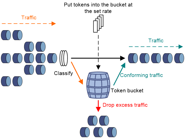
· Forwarding the packet.
· Dropping the packet.
· Forwarding the packet with its precedence re-marked.
· Delivering the packet to next-level traffic policing with its precedence re-marked.
GTS
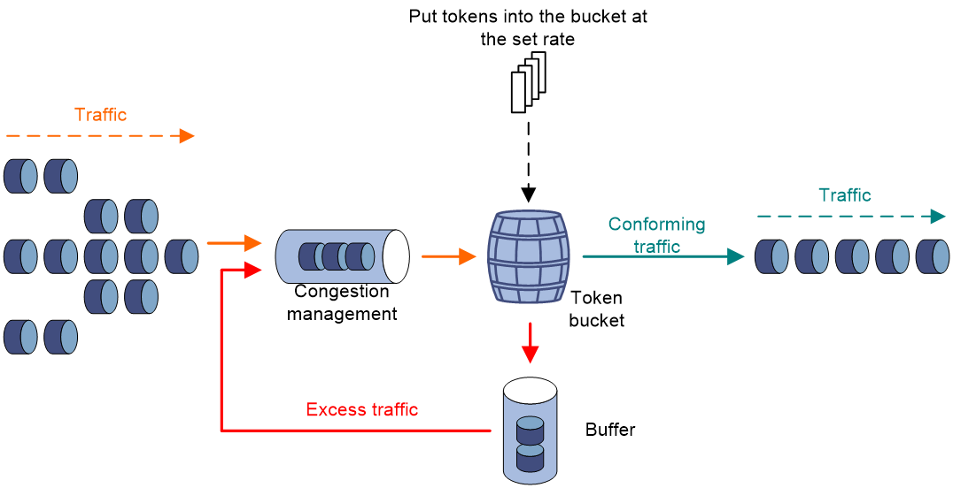
GTS limits the traffic rate by buffering exceeding traffic. You can use GTS to adapt the traffic output rate on a device to the input traffic rate of its connected device to avoid packet loss.
The differences between traffic policing and GTS are as follows:
· Packets to be dropped with traffic policing are retained in a buffer or queue with GTS, as shown in Figure 4. When enough tokens are in the token bucket, the buffered packets are sent at an even rate.
· GTS can result in additional delay and traffic policing does not.
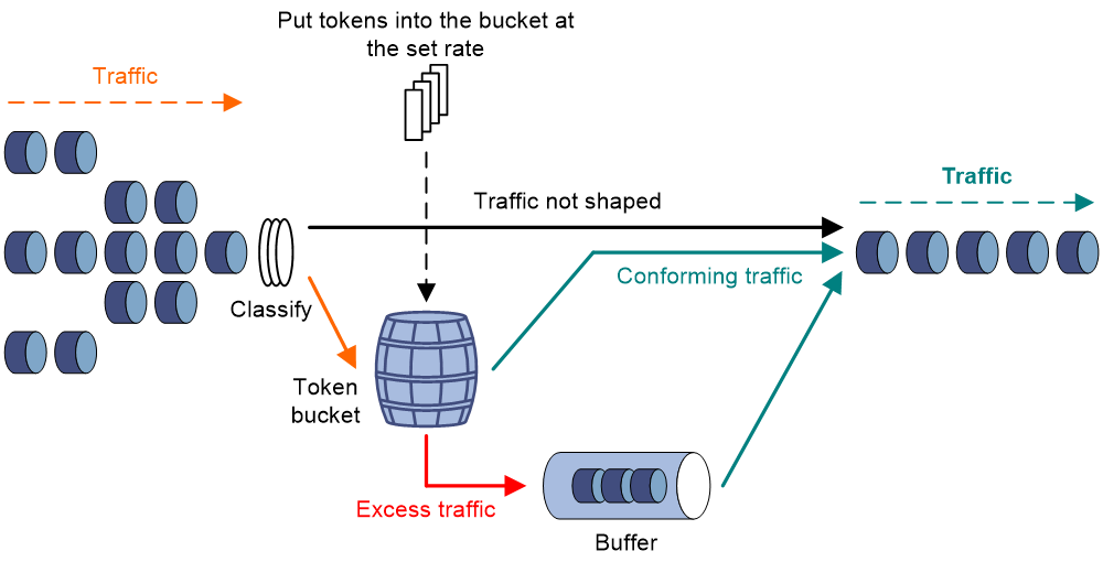
For example, in Figure 5, Device B performs traffic policing on packets from Device A and drops packets exceeding the limit. To avoid packet loss, you can perform GTS on the outgoing interface of Device A so that packets exceeding the limit are cached in Device A. Once resources are released, GTS takes out the cached packets and sends them out.

Rate limit
The rate limit of an interface specifies the maximum rate for forwarding packets (excluding critical packets).
Rate limit also uses token buckets for traffic control. When rate limit is configured on an interface, a token bucket handles all packets to be sent through the interface for rate limiting. If enough tokens are in the token bucket, packets can be forwarded. Otherwise, packets are put into QoS queues for congestion management. In this way, the traffic passing the interface is controlled.
Figure 6 Rate limit implementation
The token bucket mechanism limits traffic rate when accommodating bursts. It allows bursty traffic to be transmitted if enough tokens are available. If tokens are scarce, packets cannot be transmitted until efficient tokens are generated in the token bucket. It restricts the traffic rate to the rate for generating tokens.
Rate limit controls the total rate of all packets on an interface. It is easier to use than traffic policing in controlling the total traffic rate.
Configuring traffic policing
Traffic policing configuration approaches
You can configure traffic policing by using the MQC approach or the non-MQC approach. If both approaches are used, the MQC configuration takes effect.
You can configure the following types of traffic policing by using the non-MQC approach:
· CAR-list-based traffic policing.
· ACL-based traffic policing.
· Traffic policing for all traffic.
If traffic policing is configured by using both the MQC approach and non-MQC approach, the configuration in MQC approach takes effect.
Configuring traffic policing by using the MQC approach
Restrictions and guidelines
The device supports the following application destinations for traffic policing:
· Interface.
· Control plane.
· Control-plane management view.
Procedure
1. Enter system view.
system-view
2. Define a traffic class.
a. Create a traffic class and enter traffic class view.
traffic classifier classifier-name [ operator { and | or } ]
b. Configure a match criterion.
if-match [ not ] match-criteria
By default, no match criterion is configured.
For more information about the if-match command, see ACL and QoS Command Reference.
c. Return to system view.
quit
3. Define a traffic behavior.
a. Create a traffic behavior and enter traffic behavior view.
traffic behavior behavior-name
b. Configure a traffic policing action.
¡ In absolute value:
car cir committed-information-rate [ cbs committed-burst-size [ ebs excess-burst-size ] ] [ green action | red action | yellow action ] *
car cir committed-information-rate [ cbs committed-burst-size ] pir peak-information-rate [ ebs excess-burst-size ] [ green action | red action | yellow action ] *
¡ In percentage:
car cir percent cir-percent [ cbs cbs-time [ ebs ebs-time ] ] [ green action | red action | yellow action ] *
car cir percent cir-percent [ cbs cbs-time ] pir percent pir-percent [ ebs ebs-time ] [ green action | red action | yellow action ] *
By default, no traffic policing action is configured.
Support for this command depends on the device model. For more information, see the command reference.
c. Return to system view.
quit
4. Define a QoS policy.
a. Create a QoS policy and enter QoS policy view.
qos policy policy-name
b. Associate the traffic class with the traffic behavior in the QoS policy.
classifier classifier-name behavior behavior-name
By default, a traffic class is not associated with a traffic behavior.
c. Return to system view.
quit
5. Apply the QoS policy.
For more information, see "Applying the QoS policy."
By default, no QoS policy is applied.
Configuring CAR-list-based static traffic policing
1. Enter system view.
system-view
2. Configure a CAR list.
qos carl carl-index { dscp dscp-list | mac mac-address | mpls-exp mpls-exp-value | precedence precedence-value | { destination-ip-address | source-ip-address } { range start-ip-address to end-ip-address | subnet ip-address mask-length } [ per-address [ shared-bandwidth ] ] }
3. Enter interface view.
interface interface-type interface-number
4. Apply a CAR-list-based CAR policy to the interface.
qos car { inbound | outbound } carl carl-index cir committed-information-rate [ cbs committed-burst-size [ ebs excess-burst-size ] ] [ green action | red action | yellow action ] *
qos car { inbound | outbound } carl carl-index cir committed-information-rate [ cbs committed-burst-size ] pir peak-information-rate [ ebs excess-burst-size ] [ green action | red action | yellow action ] *
By default, no CAR policy is applied to an interface.
Configuring ACL-based traffic policing
1. Enter system view.
system-view
2. Enter interface view.
interface interface-type interface-number
3. Configure an ACL-based CAR policy on the interface.
qos car { inbound | outbound } acl [ ipv6 ] acl-number cir committed-information-rate [ cbs committed-burst-size [ ebs excess-burst-size ] ] [ green action | red action | yellow action ] *
qos car { inbound | outbound } acl [ ipv6 ] acl-number cir committed-information-rate [ cbs committed-burst-size ] pir peak-information-rate [ ebs excess-burst-size ] [ green action | red action | yellow action ] *
By default, no CAR policy is configured on an interface.
Configuring traffic policing for all traffic
1. Enter system view.
system-view
2. Enter interface view.
interface interface-type interface-number
3. Configure a CAR policy for all traffic on the interface.
qos car { inbound | outbound } any cir committed-information-rate [ cbs committed-burst-size [ ebs excess-burst-size ] ] [ green action | red action | yellow action ] *
qos car { inbound | outbound } any cir committed-information-rate [ cbs committed-burst-size ] pir peak-information-rate [ ebs excess-burst-size ] [ green action | red action | yellow action ] *
By default, no CAR policy is configured on an interface.
Configuring GTS
GTS configuration approaches
You can configure GTS by using either the MQC approach or non-MQC approach.
You can configure the following types of GTS by using the non-MQC approach:
· ACL-based GTS.
· GTS for all traffic.
If GTS is configured by using both the MQC approach and non-MQC approach, the configuration in MQC approach takes effect.
Hardware compatibility with GTS
|
F1000 series |
Models |
Feature compatibility |
|
F1000-X-G5 series |
F1000-A-G5, F1000-S-G5 |
No |
|
F1000-C-G5, F1000-C-G5-LI |
Yes |
|
|
F1000-E-G5, F1000-H-G5 |
Yes |
|
F100 series |
Models |
Feature compatibility |
|
F100-X-G5 series |
F100-A-G5 |
No |
|
F100-C-G5, F100-E-G5, F100-M-G5, F100-S-G5 |
Yes |
|
|
F100-C-A series |
F100-C-A2, F100-C-A1 |
Yes |
Configuring GTS by using the MQC approach
Restrictions and guidelines
The device supports the following application destinations for GTS:
· Interface.
· Control plane.
Procedure
1. Enter system view.
system-view
2. Define a traffic class.
a. Create a traffic class and enter traffic class view.
traffic classifier classifier-name [ operator { and | or } ]
b. Configure a match criterion.
if-match [ not ] match-criteria
By default, no match criterion is configured.
For configurable match criteria, see the if-match command in ACL and QoS Command Reference.
c. Return to system view.
quit
3. Define a traffic behavior.
a. Create a traffic behavior and enter traffic behavior view.
traffic behavior behavior-name
b. Configure a GTS action.
- In absolute value:
gts cir committed-information-rate [ cbs committed-burst-size [ ebs excess-burst-size ] ] [ queue-length queue-length ]
- In percentage:
gts percent cir cir-percent [ cbs cbs-time [ ebs ebs-time ] ] [ queue-length queue-length ]
By default, no GTS action is configured.
c. Return to system view.
quit
4. Define a QoS policy.
a. Create a QoS policy and enter QoS policy view.
qos policy policy-name
b. Associate the class with the traffic behavior in the QoS policy.
classifier classifier-name behavior behavior-name
By default, a traffic class is not associated with a traffic behavior.
c. Return to system view.
quit
5. Apply the QoS policy.
For more information, see "Applying the QoS policy."
By default, no QoS policy is applied.
Configuring ACL-based GTS
Restrictions and guidelines
ACL-based GTS takes effect only on outbound traffic.
Prodecure
1. Enter system view.
system-view
2. Enter interface view.
interface interface-type interface-number
3. Configure ACL-based GTS on the interface.
qos gts acl [ ipv6 ] acl-number cir committed-information-rate [ cbs committed-burst-size [ ebs excess-burst-size ] ] [ queue-length queue-length ]
By default, GTS is not configured on an interface.
Configuring GTS for all traffic
Restrictions and guidelines
GTS for all traffic takes effect only on outbound traffic.
Prodecure
1. Enter system view.
system-view
2. Enter interface view.
interface interface-type interface-number
3. Configure GTS on the interface.
qos gts any cir committed-information-rate [ cbs committed-burst-size [ ebs excess-burst-size ] ] [ queue-length queue-length ]
By default, GTS is not configured on an interface.
Configuring the rate limit
Hardware compatibility with rate limit
|
F1000 series |
Models |
Feature compatibility |
|
F1000-X-G5 series |
F1000-A-G5, F1000-S-G5 |
No |
|
F1000-C-G5, F1000-C-G5-LI |
Yes |
|
|
F1000-E-G5, F1000-H-G5 |
Yes |
|
F100 series |
Models |
Feature compatibility |
|
F100-X-G5 series |
F100-A-G5 |
No |
|
F100-C-G5, F100-E-G5, F100-M-G5, F100-S-G5 |
Yes |
|
|
F100-C-A series |
F100-C-A2, F100-C-A1 |
Yes |
Configuring the rate limit for an interface
1. Enter system view.
system-view
2. Enter interface view.
interface interface-type interface-number
3. Configure the rate limit for the interface.
qos lr outbound cir committed-information-rate [ cbs committed-burst-size [ ebs excess-burst-size ] ]
By default, no rate limit is configured on an interface.
Including the physical layer header in calculating the packet length for rate limiting
About this task
By default, the device calculates the packet length for rate limiting based on the data link layer frame. This feature allows the device to include a 24-byte physical layer header in calculating the packet length for rate limiting.
Restrictions and guidelines
This feature takes effect only on Layer 3 Ethernet interfaces and Layer 3 aggregate interfaces.
Procedure
1. Enter system view.
system-view
2. Include the physical layer header in calculating the packet length for rate limiting.
qos overhead layer physical
By default, the device calculates the packet length for rate limiting based on the data link layer frame.
Display and maintenance commands for traffic policing, GTS, and rate limit
Execute display commands in any view.
|
Task |
Command |
|
Display CAR configuration and statistics on an interface. |
display qos car interface [ interface-type interface-number ] |
|
Display CAR list information. |
display qos carl [ carl-index ] [ slot slot-number ] |
|
Display GTS configuration and statistics for interfaces. |
display qos gts interface [ interface-type interface-number ] |
|
Display rate limit configuration and statistics. |
display qos lrinterface [ interface-type interface-number ] |
|
Display traffic behavior configuration. |
display traffic behavior user-defined [ behavior-name ] [ slot slot-number ] |
Configuring traffic filtering
About traffic filtering
You can filter in or filter out traffic of a class by associating the class with a traffic filtering action. For example, you can filter packets sourced from an IP address according to network status.
Restrictions and guidelines: Traffic filtering configuration
The device supports applying traffic filtering to an interface or control plane.
Procedure
1. Enter system view.
system-view
2. Define a traffic class.
a. Create a traffic class and enter traffic class view.
traffic classifier classifier-name [ operator { and | or } ]
b. Configure a match criterion.
if-match [ not ] match-criteria
By default, no match criterion is configured.
For more information about configuring match criteria, see ACL and QoS Command Reference.
c. Return to system view.
quit
3. Define a traffic behavior.
a. Create a traffic behavior and enter traffic behavior view.
traffic behavior behavior-name
b. Configure the traffic filtering action.
filter { deny | permit }
By default, no traffic filtering action is configured.
If a traffic behavior has the filter deny action, all other actions in the traffic behavior do not take effect.
c. Return to system view.
quit
4. Define a QoS policy.
a. Create a QoS policy and enter QoS policy view.
qos policy policy-name
b. Associate the traffic class with the traffic behavior in the QoS policy.
classifier classifier-name behavior behavior-name
By default, a traffic class is not associated with a traffic behavior.
c. Return to system view.
quit
5. Apply the QoS policy.
For more information, see "Applying the QoS policy."
By default, no QoS policy is applied.
6. (Optional.) Display the traffic filtering configuration.
display traffic behavior user-defined [ behavior-name ] [ slot slot-number ]
This command is available in any view.
Configuring priority marking
About priority marking
Priority marking sets the priority fields or flag bits of packets to modify the priority of packets. For example, you can use priority marking to set IP precedence or DSCP for a class of IP packets to control the forwarding of these packets.
1. Configure a traffic behavior with a priority marking action.
2. Associate the traffic class with the traffic behavior.
Configuring priority marking
Restrictions and guidelines
The device supports applying priority marking to an interface or control plane.
Procedure
1. Enter system view.
system-view
2. Define a traffic class.
a. Create a traffic class and enter traffic class view.
traffic classifier classifier-name [ operator { and | or } ]
b. Configure a match criterion.
if-match [ not ] match-criteria
By default, no match criterion is configured.
For more information about the if-match command, see ACL and QoS Command Reference.
c. Return to system view.
quit
3. Define a traffic behavior.
a. Create a traffic behavior and enter traffic behavior view.
traffic behavior behavior-name
b. Configure a priority marking action.
For configurable priority marking actions, see the remark commands in ACL and QoS Command Reference.
c. Return to system view.
quit
4. Define a QoS policy.
a. Create a QoS policy and enter QoS policy view.
qos policy policy-name
b. Associate the traffic class with the traffic behavior in the QoS policy.
classifier classifier-name behavior behavior-name
By default, a traffic class is not associated with a traffic behavior.
c. Return to system view.
quit
5. Apply the QoS policy.
For more information, see "Applying the QoS policy."
By default, no QoS policy is applied.
6. (Optional.) Display the priority marking configuration.
display traffic behavior user-defined [ behavior-name ] [ slot slot-number ]
This command is available in any view.
Appendixes
Appendix A Acronyms
Table 1 Appendix A Acronyms
|
Acronym |
Full spelling |
|
AF |
Assured Forwarding |
|
BE |
Best Effort |
|
BQ |
Bandwidth Queuing |
|
CAR |
Committed Access Rate |
|
CBS |
Committed Burst Size |
|
CBQ |
Class Based Queuing |
|
CE |
Congestion Experienced |
|
CIR |
Committed Information Rate |
|
CQ |
Custom Queuing |
|
DiffServ |
Differentiated Service |
|
DSCP |
Differentiated Services Code Point |
|
EBS |
Excess Burst Size |
|
ECN |
Explicit Congestion Notification |
|
EF |
Expedited Forwarding |
|
FIFO |
First in First out |
|
FQ |
Fair Queuing |
|
GMB |
Guaranteed Minimum Bandwidth |
|
GTS |
Generic Traffic Shaping |
|
IntServ |
Integrated Service |
|
ISP |
Internet Service Provider |
|
LLQ |
Low Latency Queuing |
|
LSP |
Label Switched Path |
|
MPLS |
Multiprotocol Label Switching |
|
PE |
Provider Edge |
|
PIR |
Peak Information Rate |
|
PQ |
Priority Queuing |
|
PW |
Pseudowire |
|
QoS |
Quality of Service |
|
QPPB |
QoS Policy Propagation Through the Border Gateway Protocol |
|
RED |
Random Early Detection |
|
RSVP |
Resource Reservation Protocol |
|
RTP |
Real-Time Transport Protocol |
|
SP |
Strict Priority |
|
ToS |
Type of Service |
|
VoIP |
Voice over IP |
|
VPN |
Virtual Private Network |
|
WFQ |
Weighted Fair Queuing |
|
WRED |
Weighted Random Early Detection |
|
WRR |
Weighted Round Robin |
Appendix B Introduction to packet precedence
IP precedence and DSCP values
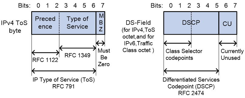
As shown in Figure 7, the ToS field in the IP header contains 8 bits. The first 3 bits (0 to 2) represent IP precedence from 0 to 7. According to RFC 2474, the ToS field is redefined as the differentiated services (DS) field. A DSCP value is represented by the first 6 bits (0 to 5) of the DS field and is in the range 0 to 63. The remaining 2 bits (6 and 7) are reserved.
Table 2 IP precedence
|
IP precedence (decimal) |
IP precedence (binary) |
Description |
|
0 |
000 |
Routine |
|
1 |
001 |
priority |
|
2 |
010 |
immediate |
|
3 |
011 |
flash |
|
4 |
100 |
flash-override |
|
5 |
101 |
critical |
|
6 |
110 |
internet |
|
7 |
111 |
network |
Table 3 DSCP values
|
DSCP value (decimal) |
DSCP value (binary) |
Description |
|
46 |
101110 |
ef |
|
10 |
001010 |
af11 |
|
12 |
001100 |
af12 |
|
14 |
001110 |
af13 |
|
18 |
010010 |
af21 |
|
20 |
010100 |
af22 |
|
22 |
010110 |
af23 |
|
26 |
011010 |
af31 |
|
28 |
011100 |
af32 |
|
30 |
011110 |
af33 |
|
34 |
100010 |
af41 |
|
36 |
100100 |
af42 |
|
38 |
100110 |
af43 |
|
8 |
001000 |
cs1 |
|
16 |
010000 |
cs2 |
|
24 |
011000 |
cs3 |
|
32 |
100000 |
cs4 |
|
40 |
101000 |
cs5 |
|
48 |
110000 |
cs6 |
|
56 |
111000 |
cs7 |
|
0 |
000000 |
be (default) |
802.1p priority
802.1p priority lies in the Layer 2 header. It applies to occasions where Layer 3 header analysis is not needed and QoS must be assured at Layer 2.
Figure 8 An Ethernet frame with an 802.1Q tag header
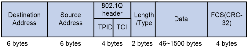
As shown in Figure 8, the 4-byte 802.1Q tag header contains the 2-byte tag protocol identifier (TPID) and the 2-byte tag control information (TCI). The value of the TPID is 0x8100. Figure 9 shows the format of the 802.1Q tag header. The Priority field in the 802.1Q tag header is called 802.1p priority, because its use is defined in IEEE 802.1p. Table 4 shows the values for 802.1p priority.
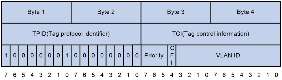
Table 4 Description on 802.1p priority
|
802.1p priority (decimal) |
802.1p priority (binary) |
Description |
|
0 |
000 |
best-effort |
|
1 |
001 |
background |
|
2 |
010 |
spare |
|
3 |
011 |
excellent-effort |
|
4 |
100 |
controlled-load |
|
5 |
101 |
video |
|
6 |
110 |
voice |
|
7 |
111 |
network-management |