- Table of Contents
- Related Documents
-
| Title | Size | Download |
|---|---|---|
| 01-Text | 7.57 MB |
Contents
Examining the installation environment
Examining the installation site
Checking power distribution or power supply environment
Installing the switch in a 19-inch rack
Installation procedure at a glance
Rack-mounting the switch by using front mounting brackets
Rack-mounting the switch by using front and rear mounting brackets
Mounting the switch on a workbench
Connecting the grounding cable
Grounding the switch by using a grounding strip
Grounding the switch by using a grounding conductor buried in the earth ground
Verifying the connection after grounding the switch
Connecting a DC power cord (using a terminal block)
Installing and removing an expansion module
Installing an expansion module
Accessing the switch for the first time
Connecting the switch to a configuration terminal
Connecting a DB9-to-RJ45 console cable
Connecting a USB-to-RJ45 console cable
Planning for setting up an IRF fabric
IRF fabric size and member switch installation location
IRF member roles and member IDs
Configuring basic IRF settings
Connecting the IRF member switches
Verifying the IRF fabric setup
Maintenance and troubleshooting
Configuration terminal display issues
No display on the configuration terminal
Garbled display on the configuration terminal
Preparing for installation
This document applies to the following Ethernet switch models:
· IE4520-30S-C
· IE4520-30S-C-DC
· IE4520-54S-C
· IE4520-54S-C-SEC
Safety recommendations
To avoid bodily injury or damage to the switch, read the following safety recommendations carefully before working with the switch. Note that the recommendations do not cover every possible hazardous condition.
· Before cleaning the switch, remove all power cords from the switch. Do not clean the switch with wet cloth or liquid.
· Do not place the switch near water or in a damp environment. Prevent water or moisture from entering the switch chassis.
· Do not place the switch on an unstable case or desk.
· Ensure adequate ventilation for the switch and keep the protective vents of the switch unblocked.
· The switch can operate correctly only under correct voltage. Ensure that the input voltage is in the required voltage range labeled on the switch.
· To avoid electrical shocks, do not open the chassis while the switch is operating. As a best practice, do not open the chassis even if the switch is powered off.
· When installing the switch, always wear an ESD wrist strap. Make sure the wrist strap makes good skin contact and is reliably grounded.
Examining the installation environment
Before installing the switch, examine the installation environment. To ensure correct operation of your switch, make sure the installation environment meets the requirements listed in Table 1.
Table 1 Checking list for the installation environment
|
Item |
Requirements |
|
Ventilation and heat dissipation |
To ensure correct operation of your device, make sure the installation environment is adequately ventilated to prevent the switch from overheating. · Ensure a minimum clearance of 10 cm (3.94 in) around the chassis. · Do not install the device near a heat source, for example, a stove or heater. · Ensure air ventilation in the installation environment. · Do not block the ventilation holes in the device or power adapter. |
|
Anti-moisture |
Water or moisture might damage the circuits of the device. · Do not place the device near water or in a damp environment. · Install the switch in a clean, dry, and ventilated place where temperature is controlled in a stable range. · Make sure the installation environment is free from water leakage or condensation. If required, install a dehumidification device (such as an air conditioner with a dehumidification function or a dedicated dehumidifier). · Do not operate the device under or near the water source, such as the wash basin, laundry room, or areas with high humidity. · Do not touch the device with wet hands. |
|
Lightning protection |
Ground the switch correctly and verify the grounding. For more information, see "Connecting the grounding cable." · If you ground the switch by using a grounding strip, make sure the grounding resistance of the grounding strip in the equipment room is less than 1W. · If you ground the switch by using a grounding conductor buried in the earth ground, make sure the grounding resistance of the grounding conductor in the ground is less than 10W. · Route the signal cables along indoor walls, bury the cables in the earth ground, or thread the cables through steel tubes. Install a signal lightning arrester with a nominal discharge current for a corresponding network interface. · Keep the signal cables far from power cords and lightning rod down conductors. · As a best practice, route power cords indoors. If an AC power cord is routed from outdoors, connect the AC power cord first to a power lightning arrester before leading it to the AC power port on the switch. Make sure the power lightning arrester has a nominal discharge current and the total length of the power cord from the power lighting arrester to the power port on the switch is less than 5 m (16.40 ft). · Ground the switch, rack, independent power supplies, and lightning arresters separately. · You must ground optical fibers with reinforcing metal stiffener from outdoors on an optical distribution frame (ODF) or fiber splice enclosure. |
|
Cable routing |
Do not run an Ethernet cable and power cord in parallel. · Route different types of cables separately. · Keep power cords a minimum of 5 cm (1.97 in) away from other cables. |
|
Mechanical environment |
NOTE: 4M represents the mechanical environment condition defined by GB/T 4798.4. It has eight classes. The 4M4 class refers to places impacted by machines, running vehicles, ground blasting or piling. |
|
Dust and water resistance |
If you install the switch in an outdoor environment, make sure the installation and operating environments meet the requirements of IP55 rating protection. NOTE: IP indicates International Protection Rating. The first number "5" refers to the rating for preventing the solid particle from entering the cabinet. An outdoor cabinet cannot prevent dust intrusion perfectly, but the dust cannot damage the device. The second number "5" refers to the rating for preventing water from entering the cabinet. Water projected in jets against the enclosure from any direction cannot damage the device. |
|
ESD prevention |
· Ground the switch correctly. · To avoid ESD damage to the device or components, always wear an ESD wrist strap when you install or remove the device or components. · Make sure the wrist strap has good skin contact and is reliably grounded. |
|
Corrosive gas prevention |
The installation site must be free from corrosive gases such as acid gases and alkaline gases. |
|
EMI |
· If AC power is used, use a single-phase three-wire power receptacle with protection earth (PE) to filter interference from the power grid. · Keep the device far away from radio transmitting stations, radar stations, and high-frequency devices. · Use electromagnetic shielding, for example, shielded interface cables, when necessary. |
Examining the installation site
Before you install the switch, verify that the installation site meets the installation requirements. The switch can operate correctly in an A1, A2, or A3 installation site. Availability issues might occur if you install the switch in a B1, B2, or C installation site.
|
Category |
Definition |
Example |
|
A1: indoor controlled environment |
· Indoor environments where temperature and humidity are controlled. · Completely enclosed or shielded indoor environments. |
Central equipment rooms, IDC equipment rooms, mobile cabins with air conditioners, outdoor air conditioner cabinets, and heat exchanger cabinets. |
|
A2: indoor partially controlled environment |
· Indoor environments where temperature and humidity are partially controlled. · Incompletely enclosed or shielded places. · Places far from pollution sources. |
Simple equipment rooms, ordinary houses, garages, corridors, and direct ventilation cabinets far from pollution sources, houses without direct exposure to sunlight or rain, railway station platforms, and stadiums. |
|
A3: indoor uncontrolled environment |
· Indoor environments where temperature and humidity are uncontrolled. · Incompletely enclosed or shielded places. · Places near pollution sources. |
Simple equipment rooms, ordinary houses, garages, corridors, and direct ventilation cabinets near pollution sources, houses without direct exposure to sunlight or rain, railway station platforms, stadiums, uncleaned rooms after decoration, and rooms under decoration. |
|
B1: outdoor general environment |
· Unshielded places where the temperature and humidity are not controlled. · Places far from pollution sources. |
Completely exposed outdoor places far from pollution sources. |
|
B2: harsh environment |
· Unshielded places where the temperature and humidity are not controlled. · Sea environments or outdoor land environments near pollution sources. |
Islands, ships, and completely exposed outdoor places near pollution sources. |
|
C: special environments |
Special application environments |
Buried, underwater, or undersea environments and manholes. |
Table 3 Pollution sources
|
Category |
Radius range |
|
Saline water areas such as oceans and saline lakes |
≤ 3.7 km (2.30 miles) |
|
Serious pollution sources such as metallurgic plants, coal mines, and heat and power plants |
≤ 3 km (1.86 miles) |
|
Medium pollution sources such as chemical factories, rubber plants, and electroplating factories |
≤ 2 km (1.24 miles) |
|
Light pollution sources, such as food factories, tanneries, and heating boilers |
≤ 1 km (0.62 miles) |
Checking power distribution or power supply environment
Table 4 Requirements for power distribution or power supply environment
|
Item |
Requirements |
|
Preparation |
The power supply must be available before you install the switch. |
|
Voltage |
The voltage provided to the switch must be within the operating voltage range. For the operating voltage range, see hardware information and specifications for the switch series. |
|
Power receptacle and cables |
· If the external power supply system provides an AC power outlet, use a country-specific AC power cord. Make sure the PE wire of the AC power supply is grounded reliably. · If the external power supply system provides a DC distribution box, provide DC power cords yourself. |
Laser safety
|
|
WARNING! The switch is a Class 1 laser device. Please use Class 1 laser transceiver modules certified by UL or CDRH. Disconnected optical fibers or transceiver modules might emit invisible laser light. Do not stare into beams or view directly with optical instruments when the switch is operating. |
Installation tools
No installation tools are provided with the switch. Prepare the following tools yourself as required:
· Flat-head screwdriver
· Phillips screwdriver
· ESD wrist strap
· Needle-nose pliers
· Diagonal pliers
· Cable crimping tool
· Marker
Installation accessories
Before installation, make sure you have all the required installation accessories. If an installation accessory is damaged or lost, purchase a new one by using the BOM part number in Table 5.
Table 5 Installation accessories
|
BOM part number |
Description |
Quantity |
Applicable switch models |
|
|
2150A03X |
Front mounting bracket kit, including a pair of mounting brackets and eight M4 screws
|
1 kit, provided |
IE4520-30S-C IE4520-30S-C-DC |
|
|
2150A09X |
Front mounting bracket kit with cable management brackets, including a pair of mounting brackets each attached with a cable management bracket and eight M4 screws
|
1 kit, provided |
IE4520-54S-C IE4520-54S-C-SEC |
|
|
2150A0BP |
Rear mounting bracket kit (including a pair of rear mounting brackets and two shoulder screws)
|
1 kit, provided |
IE4520-54S-C IE4520-54S-C-SEC |
|
|
N/A |
M6 screw and cage nut
|
User supplied |
All IE4520 switch models |
|
|
63200063 |
Rubber feet
|
4, provided |
All IE4520 switch models |
|
|
0404A0WV |
Grounding cable
|
1, provided |
All IE4520 switch models |
|
|
N/A |
Grounding screw
|
1, provided |
All IE4520 switch models |
|
|
N/A |
Interface module filler panel
|
3, provided |
All IE4520 switch models |
|
|
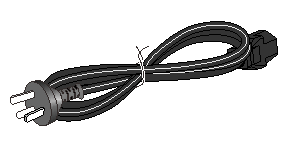
04041104 |
AC power cord
The AC power cord appearance and specifications vary by country and region. The power cord in this figure is a standard AC power cord used in China. |
1, provided |
All IE4520 switch models |
|
|
N/A |
Releasable cable tie
|
2, provided |
All IE4520 switch models |
|
|
04042967 |
DB9-to-RJ45 console cable |
1, optional |
All IE4520 switch models |
|
|
0404A1EE |
USB-to-RJ45 console cable
|
1, optional |
All IE4520 switch models |
|
|
14990101 |
SFP+ dust plug
|
Same number as that of the SFP+ ports, provided |
All IE4520 switch models |
|
|
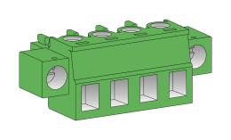
N/A |
Terminal block
|
1, provided |
All IE4520 switch models |
|


Installing the switch
|
|
CAUTION: Keep the tamper-proof seal on a mounting screw on the chassis cover intact, and if you want to open the chassis, contact H3C for permission. Otherwise, H3C shall not be liable for any consequence. |
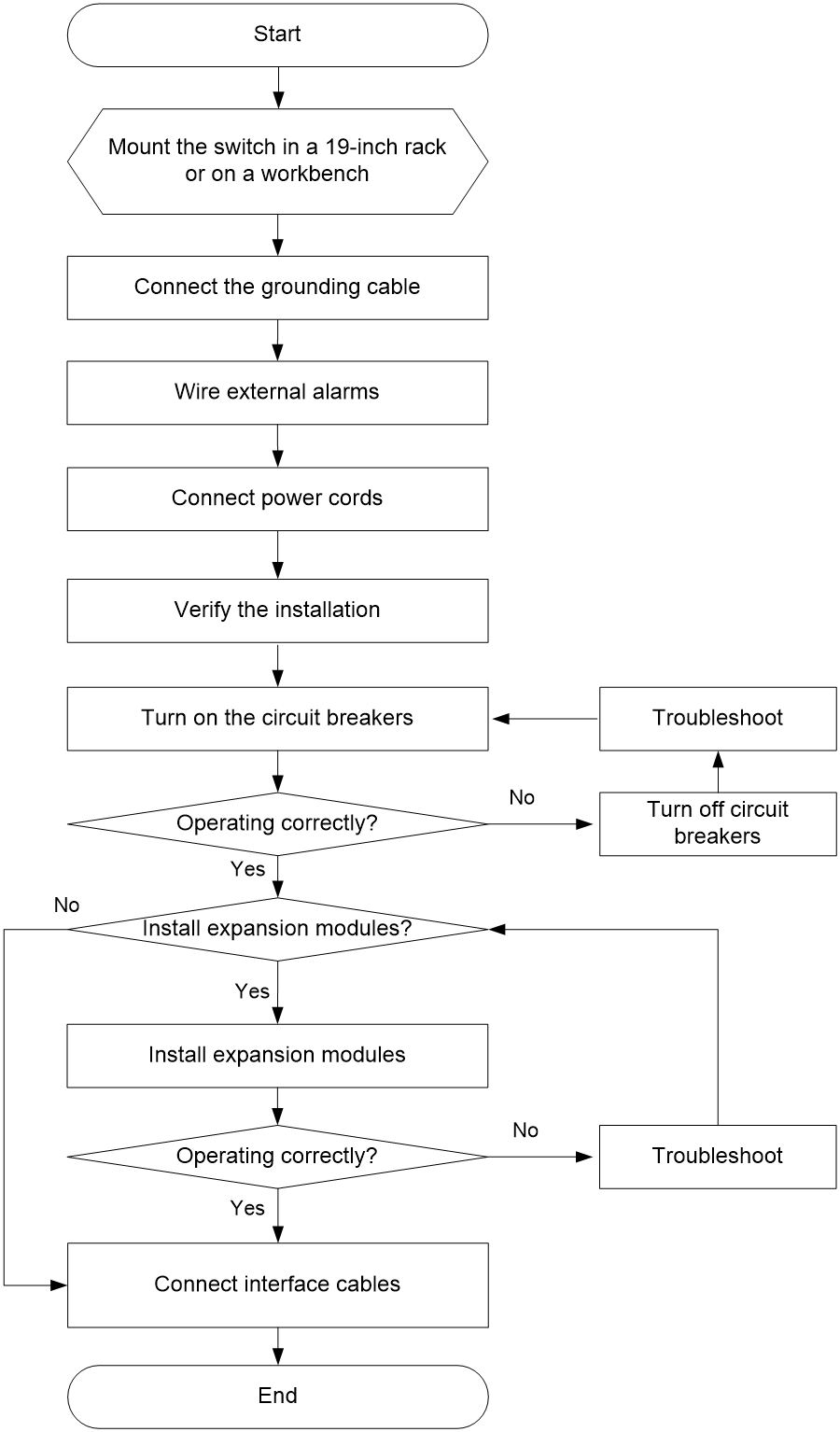
Installation flowchart
Figure 1 Installation flowchart
Installing the switch in a 19-inch rack
Installation methods
|
Applicable switch models |
Installation method |
Requirements and guidelines |
Installation procedure |
|
IE4520-30S-C IE4520-30S-C-DC |
Using front mounting brackets |
Select an installation position for the front mounting brackets as required: near the power supply side or port side. |
See "Rack-mounting the switch by using front mounting brackets." |
|
IE4520-54S-C IE4520-54S-C-SEC |
Using front and rear mounting brackets |
· Select an installation position for the front mounting brackets as required: near the power supply side or port side. · Install the rear mounting brackets based on the rack depth (distance between the front and rear rack posts). ¡ If the rack depth is in the range of 350 to 450 mm (13.78 to 17.72 in), orient the rear mounting brackets with the wide flange inside the rack. ¡ If the rack depth is in the range of 200 to 325 mm (7.87 to 12.80 in) and the distance from the rear rack posts to the inner surface of the cabinet door is greater than 155 mm (6.10 in), orient the rear mounting brackets with the wide flange outside the rack. · To install front mounting brackets with cable management brackets near the port side, make sure the installation position is a minimum of 95 mm (3.74 in) away from the rack door for the rack door to close easily. |
See "Rack-mounting the switch by using front and rear mounting brackets." |
Installation procedure at a glance
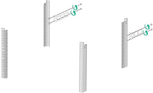
Figure 2 Procedure for installing the switch in a 19-inch rack by using front mounting brackets
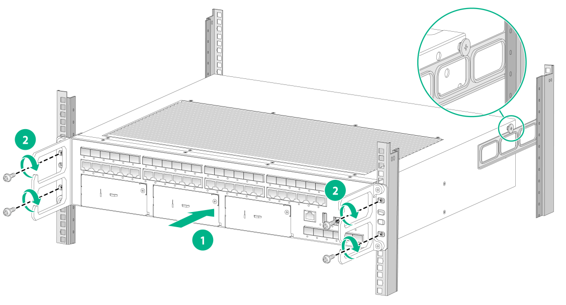
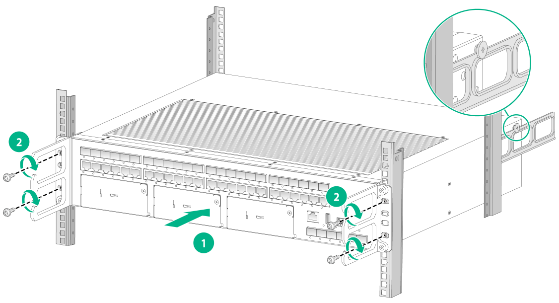
Figure 3 Procedure for installing the switch in a 19-inch rack by using front and rear mounting brackets

|
|
NOTE: If a rack shelf is available, you can put the switch on the rack shelf, slide the switch to an appropriate location, and attach the switch to the rack by using the mounting brackets. |
Mounting brackets
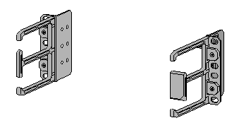
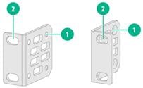
Figure 4 Front mounting brackets (1)
|
(1) Screw hole for attaching the bracket to the switch |
|
(2) Screw hole for attaching the bracket to the front rack post |
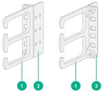
Figure 5 Front mounting brackets (2)
|
(1) Cable management bracket |
(2) Left mounting bracket |
|
(3) Right mounting bracket |
|
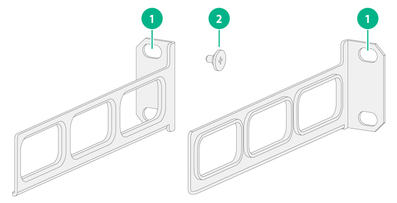
Figure 6 Rear mounting bracket and shoulder screw
|
(1) Screw holes for attaching the bracket to the rear rack post |
(2) Shoulder screw |
Rack-mounting the switch by using front mounting brackets
Only the IE4520-30S-C and IE4520-30S-C-DC switches support this rack-mounting method.
Attaching the front mounting brackets to the switch
The switch has one mounting position near the network ports and the other mounting position near the power supplies for the front mounting brackets. Select one position as needed.
To attach the front mounting brackets to the chassis:
1. Place the wide flange of the mounting bracket against the chassis side panel. Align the mounting bracket installation holes with the screw holes in the chassis.
¡ To install the mounting brackets at the port-side mounting position, see Figure 7.
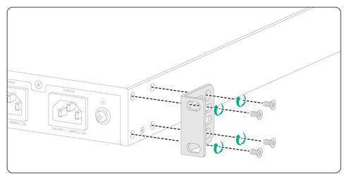
¡ To install the mounting brackets at the power supply-side mounting position, see Figure 8.
2. Fasten the M4 screws to secure the mounting bracket to the switch.
3. Attach the front mounting bracket to the other side of the chassis in the same way.
Figure 7 Attaching the front mounting brackets to the port-side mounting position
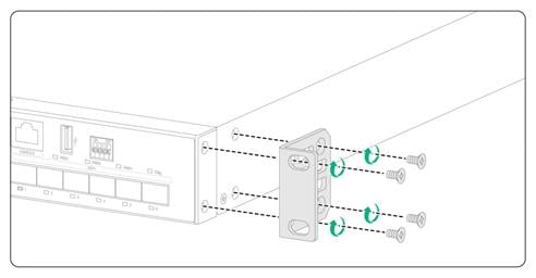
Figure 8 Attaching the front mounting brackets to the power supply-side mounting position
Mounting the switch in the rack
This task requires two people.
To mount the switch in the rack:
1. Wear an ESD wrist strap and make sure it makes good skin contact and is reliably grounded.
2. Verify that the front mounting brackets have been securely attached to the switch chassis. See "Attaching the front mounting brackets to the switch."
3. Attach cage nuts to the front rack posts.
4. One person supports the bottom of the switch, and moves the switch to an appropriate position based on the installation positions of the front mounting brackets.
5. Another person uses user supplied M6 screws and cage nuts to attach the mounting brackets to the rack and verifies that the brackets are level and secure.
Figure 9 Mounting the switch in the rack (port-side mounting position for the front mounting brackets)
Rack-mounting the switch by using front and rear mounting brackets
Only the IE4520-54S-C and IE4520-54S-C-SEC support rack-mounting by using front and rear mounting brackets.
Attaching the front mounting brackets and shoulder screws to the switch
The switch provides two installation positions on its side for the front mounting brackets. One is near the power supply side and one is near the port side. The following procedure attaches the front mounting brackets to the installation position near the port side. The power supply-side mounting is similar.
To attach the front mounting brackets and shoulder screws to the switch:
1. Wear an ESD wrist strap. Make sure the strap makes good skin contact and is reliably grounded.
2. Align the round holes in the wide flange of one front mounting bracket with the screw holes in the chassis. See Figure 10.
3. Use M4 screws (supplied with the switch) to attach the mounting bracket to the chassis.
4. Repeat the preceding two steps to attach the other mounting bracket to the chassis.
5. Unpack the shoulder screws and attach them to the chassis.
Two installation positions as red-marked in Figure 10 are available for shoulder screws. Select one as required.
Figure 10 Attaching the front mounting brackets and shoulder screws to the chassis

Attaching the rear mounting brackets to the rack
1. Determine the switch installation position in the rack.
2. Install cage nuts (user-supplied) in the rear rack posts. Make sure the corresponding cage nuts on the left and right rear rack posts are at the same height.
3. Orient the rear mounting brackets with the wide flange inside or outside the rack as required.
4. Use M6 screws (user-supplied) to attach the rear mounting brackets to the rear posts, as shown in Figure 11.
Do not fully tighten the M6 screws before mounting the switch in the rack.
Figure 11 Attaching the rear mounting brackets to the rack with the wide flange inside the rack
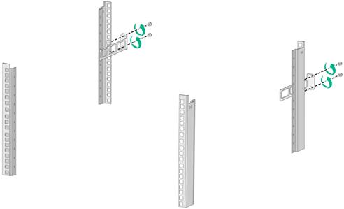
Figure 12 Attaching the rear mounting brackets to the rack with the wide flange outside the rack
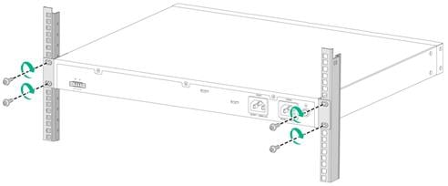
Mounting the switch in the rack
1. Wear an ESD wrist strap. Make sure the strap makes good skin contact and is reliably grounded.
2. Make sure the front mounting brackets and shoulder screws are securely attached to the two sides of the switch.
3. Attach cage nuts to the front rack posts. Make sure the corresponding cage nuts on the left and right front rack posts are at the same height.
4. One person supports the chassis bottom with one hand, holds the front part of the chassis with the other, and pushes the chassis into the rack gently. Make sure the shoulder screws rest firmly on the upper edge of the rear mounting brackets. See Figure 13 and Figure 14.
5. The other person attaches the front mounting brackets by using M6 screws and cage nuts to the front rack posts. Make sure the switch is installed securely in the rack. See Figure 13 and Figure 14.
Figure 13 Mounting the switch in the rack (with the wide flange of the rear mounting brackets inside the rack)
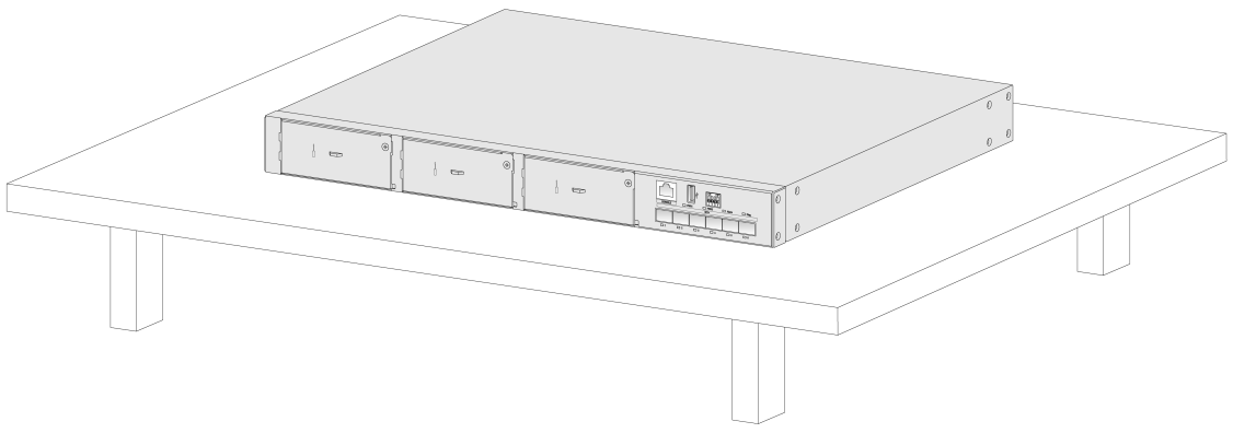
Mounting the switch on a workbench
|
|
IMPORTANT: · Reserve a minimum clearance of 10 cm (3.9 in) around the chassis for heat dissipation. · Do not place heavy objects on the switch. |
To mount the switch on a workbench:
1. Verify that the workbench is sturdy and reliably grounded.
2. Place the switch with bottom up, and clean the round holes in the chassis bottom with dry cloth.
3. Attach the rubber feet to the four round holes in the chassis bottom.
4. Place the switch with upside up on the workbench.
Figure 15 Mounting the switch on a workbench
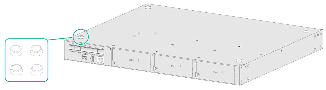
Figure 16 Switch mounted on the workbench
Connecting the grounding cable
|
|
WARNING! · Correctly connecting the grounding cable is crucial to lightning protection and ESD and EMI protection. You must connect the grounding cable correctly and reliably for the switch. · For information about lightning protection for the switch, see H3C Network Devices Lightning Protection Guide. |
To protect against the following types of issues, use a grounding cable to connect the switch to the earthing facility at the installation site:
· Bodily injury from electric shocks.
· Device and power and data line damages.
· Electrical fires, lightning strokes, electromagnetic coupling interferences, and ESD damages.
Select a grounding method based on the installation environment.
|
|
NOTE: The power and grounding terminals in this section are for illustration only. |
Grounding the switch by using a grounding strip
|
|
CAUTION: · Connect the grounding cable to the grounding strip in the equipment room. Do not connect it to a fire main or lightning rod. · To guarantee the grounding effect and avoid switch damage, use the grounding cable provided with the switch to connect the switch to a grounding strip in the equipment room. |
If a grounding strip is available at the installation site, use the grounding cable provided with the switch to connect the switch to the grounding strip.
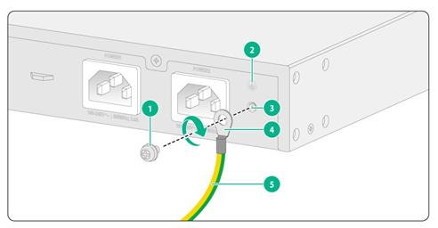
Connecting the grounding cable to the chassis
1. Remove the grounding screw from the grounding hole in the chassis.
2. Use the grounding screw to attach the ring terminal of the grounding cable to the grounding screw hole. Fasten the screw.
As a best practice, use a torque of 6.20 lb.in (0.7 Nm).
Figure 17 Connecting the grounding cable to the chassis (IE4520-30S-C)
|
(1) Grounding screw |
(2) Grounding sign |
|
(3) Grounding hole |
(4) Ring terminal |
|
(5) Grounding cable |
|
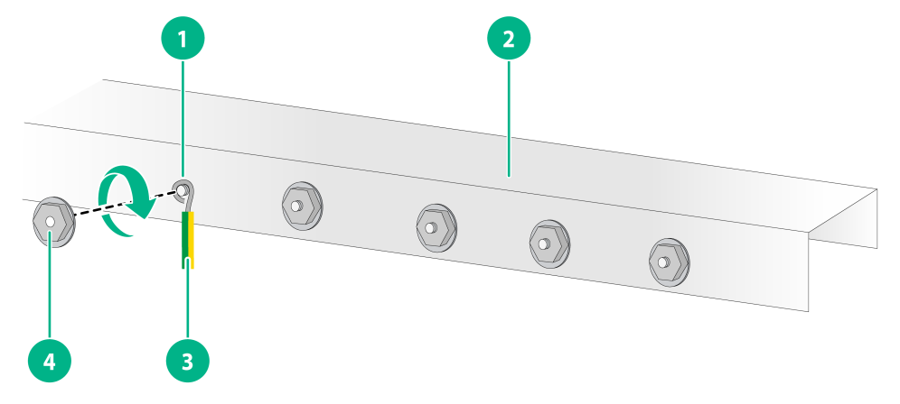
Connecting the grounding cable to a grounding strip
1. Use needle-nose pliers to bend the bare metal part to the shape as shown in Figure 18. Make sure the bended part can securely attached to the grounding post on the grounding strip.
2. Attach the bended part of the grounding cable to the grounding post and use the hex nut to fasten the bended part to the post.
Figure 18 Connecting the grounding cable to a grounding strip
|
(1) Grounding post |
(2) Grounding strip |
|
(3) Grounding cable |
(4) Hex nut |
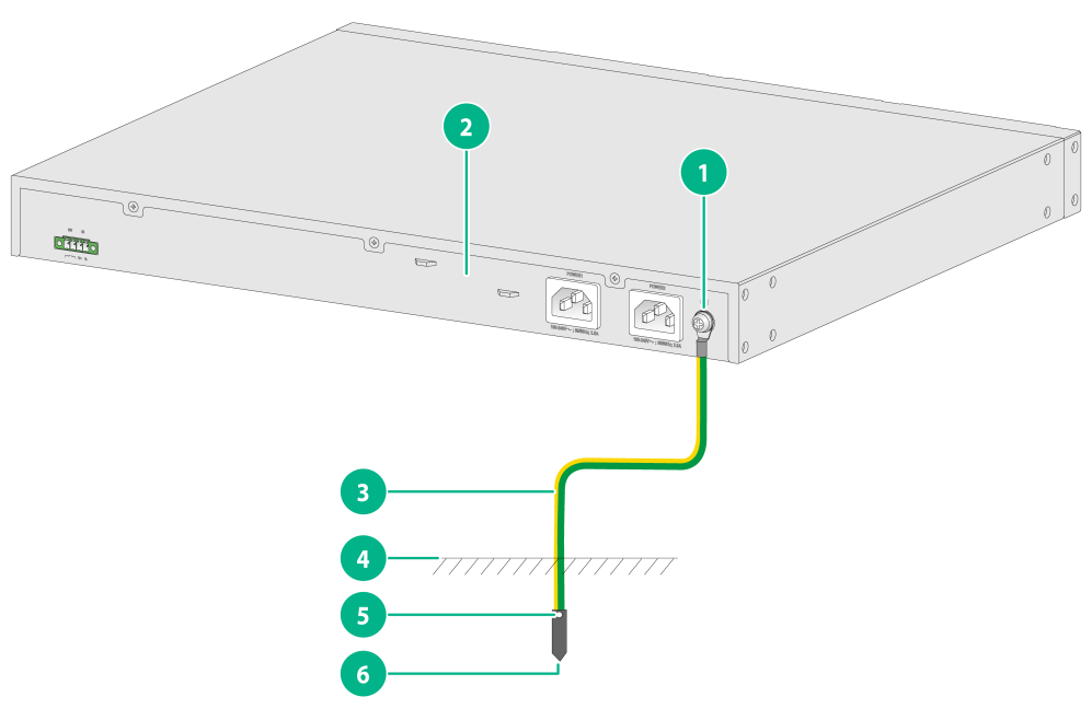
Grounding the switch by using a grounding conductor buried in the earth ground
If the installation site does not have grounding strips, but earth ground is available, hammer a 2.5 m (8.20 ft) or longer angle iron or steel tube into the earth ground to act as a grounding conductor. Make sure a minimum of 0.7 m (2.30 ft) is left between the top of the grounding conductor and the ground. In cold areas, bury the grounding conductor below the frozen soil layer. In areas with thin soil or rocky gravel, determine the depth for burying the grounding conductor based on the actual condition.
If zinc-coated steel is used, the following dimensions requirements must be met:
· Angle iron—A minimum of 50 × 50 × 5 mm (1.97 × 1.97 × 0.20 in).
· Steel tube—A minimum of 3.5 mm (0.14 in) in thickness.
· Flat steel—A minimum of 40 × 4 mm (1.57 × 0.16 in).
· Round steel—A minimum of 10 mm (0.39 in).
Weld the yellow-green grounding cable to the angel iron or steel tube and treat the joint for corrosion protection.
Figure 19 Grounding the switch by burying the grounding conductor into the earth ground
|
(1) Grounding screw |
(2) Chassis rear panel |
(3) Grounding cable |
|
(4) Earth |
(5) Welding point |
(6) Grounding conductor |
Verifying the connection after grounding the switch
· If you ground the switch with a grounding strip:
a. Use a multimeter to measure the resistance between the switch grounding terminal and grounding point, and make sure the resistance is less than 0.1W.
b. Use a grounding resistance tester to measure the grounding resistance of the grounding strip, and make sure the grounding resistance is less than 1W.
· If you ground the switch with a grounding conductor buried in the earth ground:
c. Use a multimeter to measure the resistance between the switch grounding terminal and grounding point, and make sure the resistance is less than 0.1W.
d. Use a grounding resistance tester to measure the grounding resistance of the angle iron in the ground, and make sure the grounding resistance is less than 10W. For locations with high soil resistivity, sprinkle some resistance reducer to reduce soil resistivity or replace soil around the grounding strip with soil with lower resistance.
For information about resistance measurement, see H3C Network Devices Lightning Protection Guide.
Wiring external alarms
|
|
CAUTION: · To avoid connection mistakes, identify the positive (+) and negative (-) marks above the alarm connector. · Before you wire external alarms, make sure the switch is reliably grounded and is powered off. |
The switch comes with an alarm connector installed on it. The alarm connector is used for connecting alarm signals to the switch. Before connecting wires to the alarm connector, remove the alarm connector.
No alarm input and alarm output wires are provided with the switch. Prepare compatible copper wires yourself as required. Table 6 shows the specifications for alarm input and output wires.
Table 1 Alarm input and output wire specifications
|
Switch model |
Minimum conductor cross-sectional area |
Maximum conductor cross-sectional area |
|
IE4520-30S-C IE4520-54S-C IE4520-54S-C-SEC |
0.08 mm² or 28 AWG |
0.5 mm² or 20 AWG |
The alarm output connection (DO) outputs alarms by closing or opening the relay contact. It has a current carrying capacity of 1 A/24 VDC and does not support power supply to the connected device. Connect the alarm output connection to a conventional resistive load.
Wiring external alarms
1. Choose the alarm input and output wires depending on the installation site requirements.
2. Use a wire stripper to strip the heat-shrink tubes off the input and output wires on one end, and then strip the electrical insulation off the positive (red) and negative (black) wires to make sure about 7 mm (0.28 in) of the wire reaches out.
Repeat this step for the other end.
3. Use a flat-head screwdriver to loosen the screws on the alarm connector and then remove the alarm connector.
4. Position the alarm connector upside up. Then insert the alarm input and output wires into the alarm connector as shown by callout 1 in Figure 20.
If you orient the alarm connector upside down, you cannot install it on the switch.
5. Use a flat-head screwdriver to fasten the screws at the bottom of alarm connector to secure the wires to the connector, as shown by callout 2 in Figure 20.
As a best practice, use a torque of 3.0 lb.in (0.34 Nm).
6. Attach the alarm connector to the switch. Then use a flat-head screwdriver to fasten the screws on the alarm connector to secure the connector to the switch.
7. Connect the other ends of the input and output wires to an external device.
Figure 20 Wiring external alarms for an IE4520-30S-C switch
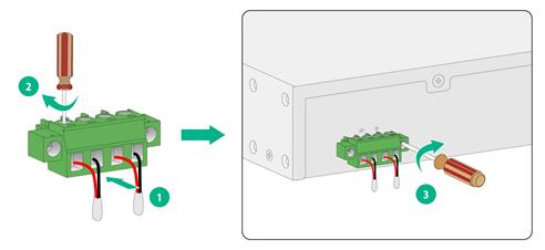
|
|
NOTE: The wire colors in the preceding figure are for illustration only. |
Connecting an AC power cord
Only the IE4520-30S-C, IE4520-54S-C, and IE4520-54S-C-SEC switches support AC power cord connection.
The switch provides two AC power receptacles on the rear panel. You can choose to use one receptacle or both for redundancy.
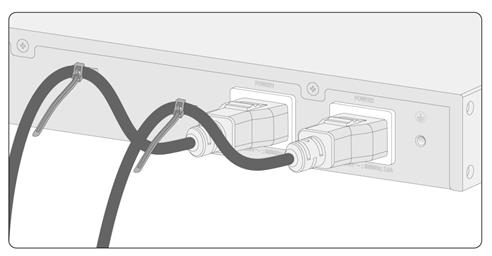
To connect an AC power cord for the switch:
1. Wear an ESD-preventive wrist strap and make sure it is reliably grounded.
2. Connect the female connector of the AC power cord to an AC-input power receptacle on the switch.
3. Use a cable tie to secure the power cord to a cable holder near the AC power receptacle. See Figure 21.
4. Connect the other end of the power cord to an AC power source.
Figure 21 Connecting the AC power cord for an IE4520-30S-C
Connecting a DC power cord (using a terminal block)
|
|
WARNING! · Make sure each power cord has a separate circuit breaker. · Turn off the circuit breaker before connecting the power cord. · To avoid connection mistakes, identify the positive (+) and negative (-) marks above the DC power receptacle before connection. |
As a best practice, use an H3C DG-240-55XX industrial power supply for DC power input. For information about the H3C DG-240-55XX industrial power supply, see H3C DG-240-55XX Industrial Power Supply Installation Quick Start.
Only the IE4520-30S-C-DC switch supports DC power cord connection. The IE4520-30S-C-DC switch comes with a terminal block for DC power connection, but it is not pre-installed on the switch
You can use the following methods to connect a DC power cord to the switch:
· Connect the DC power cord directly to the terminal block installed on the DC power receptacle.
· Connect the DC power cord to the terminal block, and then secure the terminal block to the DC power receptacle.
In this section, the second method is used as an example.
To connect a DC power cord to the switch:
1. Use a wire stripper to strip the heat-shrink tubes off the positive (red) and negative (black) two-wire power cord on one end, and then strip the electrical insulation off to make sure about 7 mm (0.28 in) of the wire reaches out.
2. Orient the terminal block with upside up and identify the positive (+) and negative (-) connections on the terminal block.
If you orient the terminal block upside down, you cannot insert it into the DC power receptacle.
3. As shown by callout 1 in Figure 22, insert the wires into the terminal block, with the positive wire to the positive connection and negative wire to the negative connection.
4. As shown by callout 2 in Figure 22, use a flat-head screwdriver to fasten the screws on the terminal block to secure the wires to the terminal block.
5. As shown by callout 3 in Figure 22, connect the terminal block to the DC power receptacle. Then use a flat-head screwdriver to fasten the screws on the block to secure the block to the power receptacle.
6. Connect the other ends of the wires to a DC power source.
Figure 22 Connecting a DC power cord for an IE4520-30S-C-DC switch
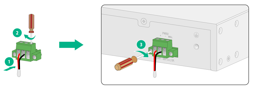
|
|
NOTE: The wire colors in the preceding figure are for illustration only. |
Installing and removing an expansion module
|
|
CAUTION: · Do not touch the surface-mounted components on an expansion module directly with your hands. · Do not use excessive force when you install or remove an expansion module. · You can install or remove an expansion module when the switch is operating correctly. Do not install or remove an expansion module while the switch is starting up. |
The installation and removal procedures are similar for interface modules. This section uses an LS5M1IEGP8 (with an ejector lever) and an LSPM6FWD (without an ejector lever) interface module as an example. Only the IE4520-54S-C-SEC switch supports the LSPM6FWD firewall module, LSWM2EC scanner module, and LSWM3EC industrial control security module and these modules can be installed only in slot 3 on the switch.
Installing an expansion module
1. Wear an ESD wrist strap. Make sure the strap makes good skin contact and is reliably grounded.
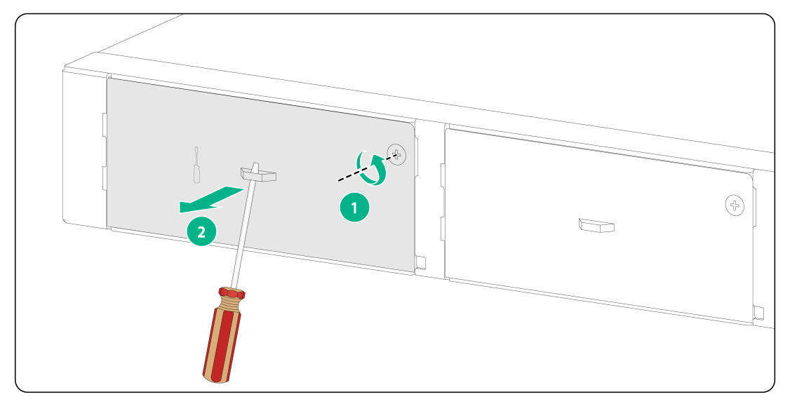
2. Use a Phillips screwdriver to remove the screw on the filler panel in the target expansion slot. Then remove the filler panel.
Keep the filler panel secure for future use.
Figure 23 Removing the filler panel from the target expansion slot
3. Unpack the expansion module.
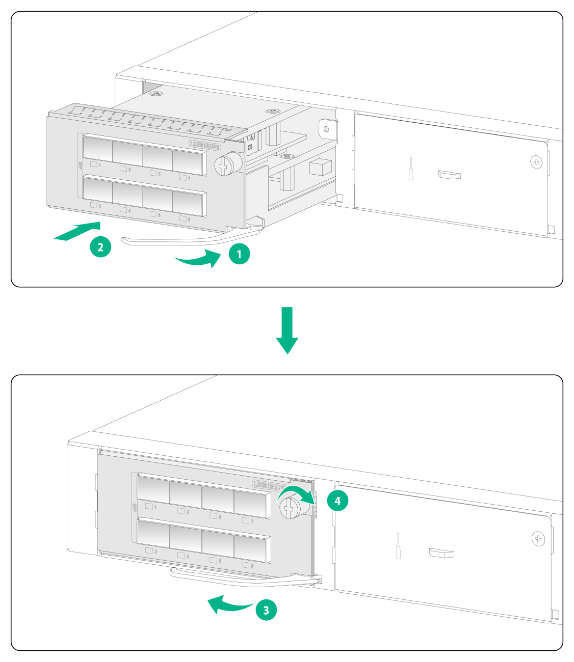
4. If the expansion module has an ejector lever, perform the following steps to install it:
a. Fully open the ejector lever, as shown by callout 1 in Figure 24.
b. Gently push the expansion module into the slot along the guide rails until the expansion module has good contact with the chassis. See callout 2 in Figure 24.
c. Close the ejector lever, as shown by callout 3 in Figure 24.
d. Use a Phillips screwdriver to fasten the captive screw on the expansion module to secure the card in the slot. See callout 4 in Figure 24.
Figure 24 Installing an expansion module with an ejector lever (LS5M1IEGP8)
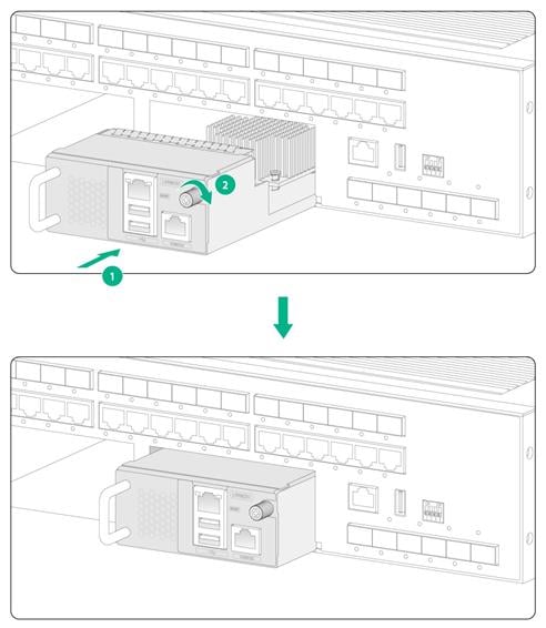
5. (Optional.) If the expansion module does not have an ejector lever, perform the following steps to install it:
a. Gently push the expansion module into the slot along the guide rails until the expansion module has good contact with the chassis. See callout 1 in Figure 25.
b. Use a Phillips screwdriver to fasten the captive screw on the expansion module to secure the card in the slot. See callout 2 in Figure 25.
Figure 25 Installing an expansion module without an ejector lever (LSPM6FWD)
|
|
NOTE: · An LSPM6FWD firewall module including its handle adds 75 mm (2.95 in) to the chassis depth when the module is installed on the switch. · An LSWM2EC EPS scanner module or LSWM3EC industrial control security module (including its handle) adds 76 mm (2.99 in) to the chassis depth when the module is installed on the switch. |
Removing an expansion module
1. Wear an ESD wrist strap. Make sure the strap makes good skin contact and is reliably grounded.
2. Use a Phillips screwdriver to remove the captive screw on the expansion module.
3. Fully open the ejector lever.
Skip this step for an expansion module that does not have an ejector lever.
4. Gently pull the expansion module out of the slot along the guide rails.
5. If you are not to install a new expansion module, install a filler panel in the slot to prevent dust and ensure good ventilation in the switch.
Verifying the installation
After you complete the installation, verify the following information:
· There is enough space around the switch for heat dissipation.
· The grounding cable is connected correctly.
· The power source is as required by the switch.
· The power cords are correctly connected.
· If an interface cable for a port is routed outdoors, verify that a network port lightning protector is used for the port.
· If a power line is routed from outdoors, verify that a surge protected power strip is used for the switch.
Accessing the switch for the first time
Connecting the switch to a configuration terminal
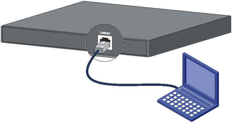
You can connect the switch to a configuration terminal by using the serial console port.
In Figure 26, the switch is connected to a configuration terminal (PC as an example) from the serial console port.
Figure 26 Connecting the switch to a configuration terminal
Console cables
You can use a DB9-to-RJ45 console cable or USB-to-RJ45 console cable as shown in Table 2 to connect the switch to a configuration terminal.
The switch is not provided with a console cable. The signal pinout for the RJ-45 connector of a serial console cable varies by vendor. To avoid abnormal configuration terminal display, use the recommended H3C DB9-to-RJ45 console cable (part number: 04042967) or H3C USB-to-RJ45 console cable (part number: 0404A1EE). To prepare a serial console cable yourself, make sure the signal pinout for the RJ-45 connector is the same as that shown in Table 3.
Table 2 Connection methods and console cables
|
Connection method |
Console cable type |
Configuration terminal-side connector |
Switch-side connector |
|
Using the serial console port for connection |
DB9-to-RJ45 console cable |
DB-9 female connector |
RJ-45 connector |
|
USB-to-RJ45 console cable |
USB connector |
RJ-45 connector |
Connecting a DB9-to-RJ45 console cable
|
|
CAUTION: Follow these guidelines when you connect a DB9-to-RJ45 console cable: · Identify the mark on the serial console port and make sure you are connecting to the correct port. · The serial ports on PCs do not support hot swapping. To connect a PC to an operating switch, first connect the PC end. To disconnect a PC from an operating switch, first disconnect the switch end. |
A DB9-to-RJ45 serial console cable is an 8-core shielded cable, with a crimped RJ-45 connector at one end for connecting to the serial console port of the switch, and a DB-9 female connector at the other end for connecting to the serial port on a configuration terminal.
Figure 27 DB9-to-RJ45 console cable
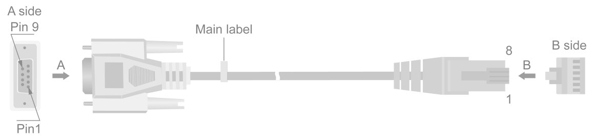
Table 3 DB9-to-RJ45 console cable signal pinout
|
RJ-45 |
Signal |
DB-9 |
Signal |
|
1 |
RTS |
8 |
CTS |
|
2 |
DTR |
6 |
DSR |
|
3 |
TXD |
2 |
RXD |
|
4 |
SG |
5 |
SG |
|
5 |
SG |
5 |
SG |
|
6 |
RXD |
3 |
TXD |
|
7 |
DSR |
4 |
DTR |
|
8 |
CTS |
7 |
RTS |
To connect the switch to a configuration terminal (for example, a PC) by using a DB9-to-RJ45 console cable:
1. Plug the DB-9 female connector of the DB9-to-RJ45 console cable to the serial port on the PC.
2. Connect the RJ-45 connector to the serial console port on the switch.
Connecting a USB-to-RJ45 console cable
|
|
IMPORTANT: · To use a USB-to-RJ45 console cable to connect the switch to a configuration terminal, first download and install the USB-to-RJ45 console driver on the configuration terminal and then connect the USB-to-RJ45 console cable to the configuration terminal. · If you have connected a USB-to-RJ45 console cable to the configuration terminal before installing the driver, remove and reconnect the USB-to-RJ45 console cable to the configuration terminal after driver installation. |
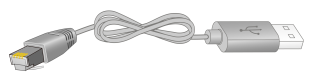
Figure 28 USB-to-RJ45 console cable
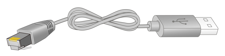
For information about the signal pinout for the RJ-45 connector of a USB-to-RJ45 console cable, see Table 3.
The following installs the driver on the Windows system. To install the driver on other operating systems, see the installation guide in the driver compression package named by using the corresponding operating system.
To connect the switch to a configuration terminal by using a USB-to-RJ45 console cable:
1. Click the following link, or copy it to the address bar on your browser and download the USB-to-RJ45 console driver.
http://www.h3c.com/en/home/USB_to_RJ45_Console/
2. View the TXT file Read me in the Windows folder to check whether the Windows system of the configuration terminal supports the driver.
3. If the Windows system supports the driver, install PL23XX-M_LogoDriver_Setup_v200_20190815.exe.
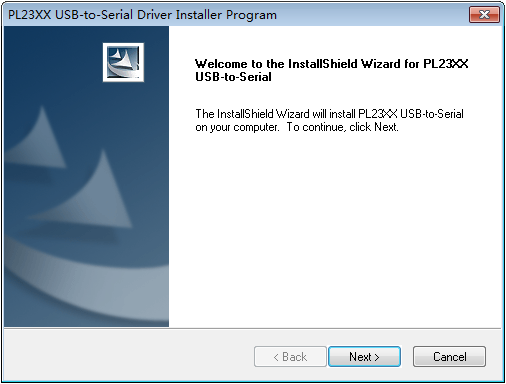
4. Click Next on the welcome page of the driver installation wizard.
Figure 29 Driver installation wizard
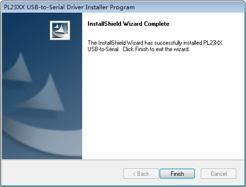
5. Click Finish after the drive installation is completed.
Figure 30 Finishing the driver installation
6. Connect the standard USB connector of the cable to the USB port of the configuration terminal.
7. Connect the RJ-45 connector of the cable to the console port of the switch.
Setting terminal parameters
To configure and manage the switch through the console port, you must run a terminal emulator program, such as TeraTermPro, on your configuration terminal. You can use the emulator program to connect a network device, a Telnet site, or an SSH site. For more information about the terminal emulator programs, see the user guides for these programs.
Configure the terminal parameters as follows:
· Bits per second—9,600.
· Data bits—8.
· Parity—None.
· Stop bits—1.
· Flow control—None.
Starting the switch
Pre-startup checklist
Before powering on the switch, verify that the following conditions are met:
· The power cord is correctly connected.
· The power source voltage is as required by the switch.
· The console cable is correctly connected.
· The configuration terminal (a PC, for example) has started, and the terminal parameters have been set correctly.
Powering on the switch
To power on the switch, connect the power cord to a power source and then turn on the circuit breaker.
During the startup process, you can access Boot ROM menus to perform tasks such as software upgrade and file management. The Boot ROM interface and menu options vary by software version. For more information about Boot ROM menu options, see the software-matching release notes for the device.
After the startup completes, you can access the CLI to configure the switch. For more information about the configuration commands and CLI, see the configuration guides and command references for the switch series.
Setting up an IRF fabric
The Intelligent Resilient Framework (IRF) technology virtualizes multiple physical devices at the same layer into one virtual fabric for simplified topology, easy management, and improved network performance and availability.
The IE4520 switch series support IRF, allowing you to connect multiple switches physically into one logical fabric and set up a new intelligent network that features high availability, scalability, and easy management.
Only switches from the same switch series can set up an IRF fabric.
IRF fabric setup flowchart
Figure 31 IRF fabric setup flowchart
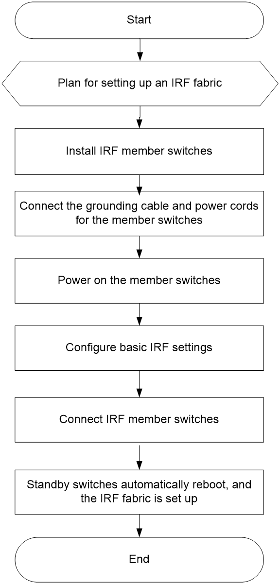
To set up an IRF fabric:
|
Step |
Description |
|
1. Plan for setting up an IRF fabric. |
Plan the following items for setting up an IRF fabric: · IRF fabric size and member switch installation location · IRF member roles and member IDs |
|
2. Install IRF member switches. |
See "Installing the switch in a 19-inch rack" and "Mounting the switch on a workbench." |
|
3. Connect the grounding cable and power cords for the switches. |
See "Connecting the grounding cable" and "Connecting an AC power cord." |
|
4. Power on the switches. |
N/A |
|
5. Configure basic IRF settings. |
See IRF Configuration Guide in the set of configuration guides for the switch series. |
|
6. Connect the IRF member switches. |
Use SFP or SFP+ transceiver modules and optical fibers for long distance connection. Use twisted pair cables, SFP transceiver modules and twisted pair cables, or SFP+ cables for short distance connection. |
|
7. Standby switches automatically reboot, and the IRF fabric is set up. |
N/A |
Planning for setting up an IRF fabric
Plan the following items for setting up an IRF fabric:
· IRF fabric size and member switch installation location
· IRF member roles and member IDs
· Candidate physical IRF ports
IRF fabric size and member switch installation location
The switching capacity of an IRF fabric equals the total switching capacities of all member switches. Determine the number and model of IRF member switches based on the network access demands and uplink requirements.
Determine the installation location for the member switches:
· Place all IRF member switches in one rack for centralized high-density access.
· Distribute the IRF member switches in different racks to implement the ToR access solution for a data center.
|
|
NOTE: An IRF fabric is highly scalable. You can easily add new member devices to an IRF fabric after the fabric is set up. |
IRF member roles and member IDs
IRF uses two member roles: master and standby. When devices form an IRF fabric, they elect a master to manage and control the IRF fabric, and all the other devices back up the master. An IRF fabric has only one master switch. When the master device fails, the other devices automatically elect a new master.
Determine which switch you want to use as the master. You can affect the election result by assigning a high member priority to the intended master switch. For more information about the master election, see IRF Configuration Guide in the set of configuration guides for the switch series.
An IRF fabric uses member IDs to uniquely identify and manage its members, and you must assign each IRF member switch a unique member ID.
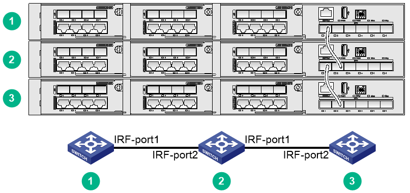
IRF network topology
You connect the IRF member switches through IRF interfaces, the logical interfaces for the connections between IRF member switches. Each IRF member switch has two IRF interfaces: IRF-interface 1 and IRF-interface 2. To use an IRF interface, you must bind a minimum of one physical port to it.
When connecting two neighboring IRF member switches, you must connect the physical ports of IRF-interface 1 on one switch to the physical ports of IRF-interface 2 on the other switch.
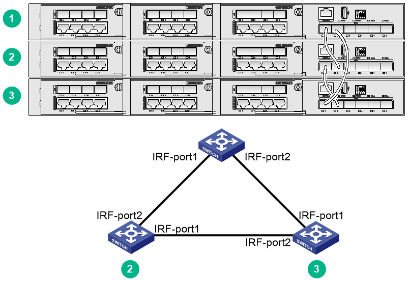
You can create an IRF fabric in daisy chain topology or more reliable ring topology. In ring topology, the failure of one IRF link does not cause the IRF fabric to split as in daisy chain topology. As a best practice, use a ring topology to create an IRF fabric.
|
|
NOTE: · The front panel of the IE4520-30S-C switch is used as an example in the following two figures. · The IRF port connections in the two figures are for illustration only, and more connection methods are available. |
Figure 32 Daisy chain topology
Multiple types of ports on the switch can be used as IRF physical ports. For more information, see Table 4.
You can bind several IRF physical ports to an IRF interface for increased bandwidth and availability.
Candidate physical IRF ports
Reserve physical IRF ports on the member switches according to your topology and connection scheme.
Table 4 shows the physical ports that can be used for IRF connection and the port use restrictions.
Table 4 Candidate physical IRF ports and use restrictions
|
Chassis |
Candidate physical IRF ports |
Use restrictions |
|
IE4520-54S-C IE4520-54S-C-SEC |
All SFP+ ports on the front panel |
The SFP ports must operate at 10 Gbps. The IRF physical ports selected on the member switches must operate at the same rate. The ports on interface modules cannot be used as IRF physical ports. |
IRF connection scheme
You can use SFP+ transceiver modules and optical fibers or SFP+ cables for IRF connection. For the available transceiver module and optical fiber models, see hardware information and specifications for the switch series.
· For a short-distance IRF connection in an equipment room, use a SFP+ cable.
· For a long-distance IRF connection, use SFP+ transceiver modules and optical fibers.
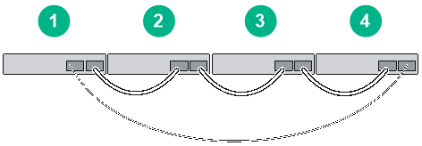
The following subsections describe several H3C recommended IRF connection schemes by using SFP+ cables and SFP+ transceiver modules and optical fibers. As a best practice, use a ring topology to set up an IRF fabric. The following figures show examples of IRF connection schemes of four switches in a ring topology.
Connecting the IRF member switches in one rack
Connect the IRF member switches (4 switches in this example) in a rack as shown in Figure 34 if the switches are in one rack.
Figure 34 Connecting the switches in one rack
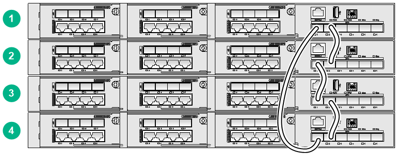
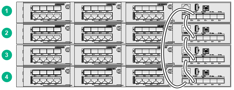
Figure 35 IRF fabric connection topology

Connecting the IRF member switches in a ToR solution
You can install IRF member switches (4 switches in this example) in different racks side by side to deploy a top of rack (ToR) solution as shown in Figure 36. Use SFP+ transceiver modules and optical fibers for connection if a large distance exists between the member switches.
Figure 36 ToR connection
Configuring basic IRF settings
After you install the IRF member switches, power on and log in to each member switch to configure basic IRF settings, including the IRF member ID, member priority (affecting the result of the master selection), and bindings between IRF interfaces and IRF physical ports.
For information about logging in to the switch, see login management configuration in Fundamentals Configuration Guide in the set of configuration guides for the switch series.
For information about configuring basic IRF settings, see IRF Configuration Guide in the set of configuration guides for the switch series.
Connecting the IRF member switches
|
|
CAUTION: Wear an ESD wrist strap when you connect the IRF physical ports. Make sure the strap makes good skin contact and is reliably grounded. |
Connect the IRF member switches based on the network topology and cabling scheme. For information about connecting the transceiver modules and cables, see H3C Transceiver Modules and Network Cables Installation Guide.
Verifying the IRF fabric setup
To verify the basic functionality of the IRF fabric after you finish configuring basic IRF settings and connecting IRF ports:
1. Log in to the IRF fabric through the console port on any member switch.
2. Create a Layer 3 interface, assign it an IP address, and make sure the IRF fabric and the remote network management station can reach each other.
3. Use Telnet or SNMP to access the IRF fabric from the network management station. (See Fundamentals Configuration Guide for the switch series.)
4. Verify that you can manage all member switches as if they were one node.
5. Display the running status of the IRF fabric by using the commands in Table 5.
Table 5 Displaying and maintaining IRF configuration and running status
|
Task |
Command |
|
Display information about the IRF fabric. |
display irf |
|
Display all members’ IRF configurations that take effect at a reboot. |
display irf configuration |
|
Display IRF fabric topology information. |
display irf topology |
|
|
NOTE: An IRF link failure causes an IRF fabric to split in two IRF fabrics operating with the same Layer 3 settings, including the same IP address. To avoid IP address collision and network issues, IRF uses multi-active detection (MAD) mechanisms to detect the presence of multiple identical IRF fabrics, handle collisions, and recover from faults. For more information about MAD, see IRF Configuration Guide in the set of configuration guides for the switch series. |
Maintenance and troubleshooting
Power supply failure
You can determine whether a power supply is faulty by observing the power supply status LED (PWR1, PWR2) on the switch.
Symptom
The power status LED on the switch indicates a power supply failure.
Resolution
To resolve the issue:
1. Verify that the power cord is connectedly correctly. Make sure the power receptacle on the switch and the power outlet are in good condition.
2. Verify that the external power system is operating correctly.
3. Verify that the operating temperature of the switch is in an acceptable range, and adequate ventilation is provided for the switch.
Over-temperature can cause the power supply to stop working and enter self-protection mode.
4. If the issue persists, contact H3C Support.
Configuration terminal display issues
No display on the configuration terminal
Symptom
The switch starts up but the configuration terminal does not have any display.
Solution
To resolve the issue:
1. Verify that the power supply is supplying power correctly to the switch.
2. Verify that the console cable is connected correctly.
3. Verify that the console cable is in good condition.
4. Verify that the terminal settings are correct.
5. If the issue persists, contact H3C Support.
Garbled display on the configuration terminal
Symptom
The configuration terminal displays garbled texts.
Resolution
To resolve the issue:
1. Verify that the configuration terminal settings are correct, as follows:
¡ Baud rate—9,600.
¡ Data bits—8.
¡ Parity—None.
¡ Stop bits—1.
¡ Flow control—None.
2. If the issue persists, contact H3C Support.
