- Table of Contents
- Related Documents
-
| Title | Size | Download |
|---|---|---|
| 01-text | 3.12 MB |
Contents
Requirements for deploying CloudOS with IaaS
Requirements for deploying CloudOS with PaaS
Requirements for deploying CloudOS with PaaS and IaaS
(Optional) IaaS installation package
(Optional) PaaS installation package
Feature and product compatibility
Connecting to ONEStor RBD storage
Configuring ONEStor cluster files on CloudOS servers
Connecting to FC storage in single-path mode
Connecting to FC storage in multipathing mode
Deploying cloud services and system components
Mounting shared storage volumes
Uploading installation packages
Deploying installation packages
Formatting non-multipath storage volumes
Formatting multipath storage volumes
Configuring edge ports on the switch
Configuring a port as an edge port
Configuring an aggregate interface as an edge aggregate interface
How do I perform a disk IO benchmark test before node deployment
What should I do if I select a wrong etcd node during node deployment
What should I do if I fail to deploy CloudOS because SELinux is disabled on a host?
About the CloudOS 5.0 system
CloudOS 5.0 is an enterprise-class container-optimized full-stack cloud platform. CloudOS uses a pluggable open architecture to provide platform services and highly scalable user applications. It offers high-performance scalable containers and centralized management of cloud services and user applications and supports microservices and fast application delivery based on agile development and DevOps.
As shown in Figure 1, CloudOS can accommodate various cloud services and provide enterprises with centralized application management capabilities. Users can use the rich management tools and flexible management policies of CloudOS to implement granular infrastructure management and improve resource usage, which ensures correct operation of applications at multiple levels.
Figure 1 CloudOS interconnecting service applications and resources

CloudOS is a unified platform that allows both developers and IT operations teams to build, deploy, and manage applications based on infrastructure. It reduces the development cycle and operations costs in application delivery for enterprises to create more interests. Focusing on application delivery, CloudOS virtualizes management and scheduling of various underlying resources to provide overall support for construction, integration, orchestration, deployment, and operation of applications in a highly available, efficient environment.
CloudOS offers the following features:
· Open-source standards—CloudOS offers OCI and Docker containers, Kubernetes container orchestration, and other open-source technologies for customers to break the limits imposed by specific vendor technologies and business roadmaps.
· Pluggable open architecture—CloudOS allows users to customize services as needed. For example, users can deploy desired services directly on CloudOS without upgrading CloudOS and offer applications as cloud services to specific subscribers according to the strategies provided by CloudOS.
· Centralized management of cloud services and user applications—CloudOS enables users to implement centralized management of cloud services and user applications by using containers.
· Microservices supporting modernization of application architectures—CloudOS can accommodate both native cloud microservices and traditional stateful applications. The rich application architectures and programming tools of CloudOS can help users fast create application prototypes.
· Fast application delivery based on agile development and DevOps—CloudOS guarantees unified standard application components for developers and IT operations teams to reduce configuration errors and automate deployment and allows for rollovers in case of failure.
About CloudOS deployment
CloudOS is a cloud platform developed based on the microservice architecture. It is deployed in cluster mode.
Deployment mode
Table 1 Cluster mode
|
Servers |
Shared Storage |
HA |
Remarks |
|
Physical: 3, 5, 7, or 9 |
CloudOS: Not required. |
Supported |
Use physical servers to host controller nodes in the CloudOS cluster. VM deployment is supported only in the UIS scenario. Deploy CloudOS in cluster mode. The maximum number of allowed failed controller nodes in a CloudOS server cluster is the number of controller nodes minus 1 and then divided by 2. The FC storage resource only supports standard FC SAN network and does not support FCoE. |
|
IaaS component: Required. ONEStor, RBD, FC, iSCSI, and NFS (for the test environment only) storage resources are supported. |
|||
|
PaaS component: Required. ONEStor, RBD, FC, iSCSI, and NFS (for the test environment only) storage resources are supported. |
Networking scheme
As shown in Figure 2, CloudOS uses the cluster mode networking scheme.
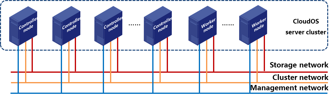
Table 2 Networking scheme description
|
Item |
Description |
|
Controller node |
Runs services of CloudOS. The controller node from which you log in to GoMatrix during component deployment is the master node. |
|
Worker node |
Runs user service containers of PaaS. |
|
CloudOS server cluster |
Contains CloudOS controller nodes and worker nodes. In deployment, a CloudOS server cluster must contain an odd number of controller nodes, and the minimum number of controller nodes is three. As a best practice, deploy three or five controller nodes in the cluster. After the cluster is deployed, you can add any number of controller nodes or worker nodes to the cluster. |
|
Management network |
Network for access and management of CloudOS and for communication between CloudOS and other cloud service components. |
|
Cluster network |
Network for communication among each node in the CloudOS server cluster. |
|
Storage network |
Network for CloudOS to connect to the storage devices. |
CloudOS 5.0 provides only the CloudOS Node role for cluster nodes. It does not distinguish between controller nodes and worker nodes when installed on the nodes.
Only controller nodes are required in initial deployment of CloudOS. You can add worker nodes from the Web interface of CloudOS after CloudOS and PaaS are deployed.
If traffic is not very large, you can use one network as the management, storage, and cluster network. For more information, see "Deploying a node."
The management network and cluster network must be the same.
The IP address of the management and cluster network for each controller node in the CloudOS cluster must belong to the same subnet. To use the IaaS bare metal service, prepare an independent bare metal compute node. For more information about installing and deploying a bare metal node, see cloud service management in H3C CloudOS 5.0 User Guide.
When you plan the network, do not use the IP addresses in the following subnets. These IP addresses are used for communications within the cluster. If your existing networks overlap with these subnets, change the system default network settings. For more information, see "Deploying a node."
· 10.240.0.0/12—Default container subnet.
· 10.100.0.0/16—Default K8s service network subnet
· 172.17.0.0/16—Default Docker bridge network subnet. Make sure the last eight bits are not 0.
System requirements
You can replace all HDDs with SSDs, as long as the capacity of the SSDs is larger than or equal to that of the HDDs. The interface type is not limited.
Make sure all controller nodes use the same configuration or use configuration with slight difference. Deployment of servers that use CPUs of different generations or architectures is not supported.
Disks with M.2 connectors are not supported.
You can deploy standalone bare metal compute nodes and cluster worker nodes only on H3C CAS and VMware vSphere products.
Browser requirements
|
Item |
Requirement |
|
Version |
Higher than Google Chrome 41 or Mozilla Firefox 41. |
|
Browser width |
1600 × 900 to 1920 × 1080 pixels. |
Requirements for deploying CloudOS with IaaS
Table 3 Controller node requirements
|
Item |
Requirements |
|
Server type |
x86 For more information, see the software and hardware compatibility matrixes. |
|
Quantity |
≥ 3 |
|
CPU |
Intel Xeon V3 or later. 24 or more CPU cores. The frequency of each core must be equivalent to or higher than 2.0 GHz. |
|
Memory |
≥ 96 GB |
|
System disk |
Two or more HDDs or SSDs: · Capacity ≥ 600GB. · Speed ≥ 10000 RPM. |
|
Data disk |
Two or more HDDs: · Capacity: 100 GB to 1 TB. · Speed ≥ 10000 RPM. As a best practice, use SSDs for etcd. |
|
RAID controller |
≥ 1GB cache (A RAID controller requires the power fail safeguard feature.) |
|
NIC |
· Four or more 1000Base-T ports. · (Optional.) Two or more 10 Gbps SFP+ ports. |
|
(Optional) Storage controller |
· IP SAN—Two or more 10 Gbps SFP+ ports. · FC SAN—Two or more 8 Gbps SFP+ FC ports. Select one as required. |
Table 4 Standalone bare metal compute node (optional)
|
Item |
Requirements |
||
|
Server type |
x86 For more information, see the software and hardware compatibility matrixes. |
||
|
Deployment mode |
VM deployment is supported. |
||
|
CPU |
Intel Xeon V3 or later. 16 or more CPU cores. The frequency of each core must be equivalent to or higher than 2.0 GHz. |
||
|
Memory |
≥ 64 GB |
||
|
System disk |
HDD |
Size |
600 GB or higher. |
|
Speed |
10000 RPM or higher. |
||
|
SSD |
Size |
600 GB or higher. Non-NVMe interface. |
|
|
RAID controller |
≥ 1GB cache (A RAID controller requires the power fail safeguard feature.) |
||
|
NIC |
Common network |
2 or more 1000 Base-T or 10-GE ports |
Link aggregation is required. |
|
Multitenant network |
6 or more 1000 Base-T or 10-GE ports |
||
Requirements for deploying CloudOS with PaaS
Table 5 Controller node requirements
|
Item |
Requirements |
|
Server type |
x86 For more information, see the software and hardware compatibility matrixes. |
|
Quantity |
≥ 3 |
|
CPU |
Intel Xeon V3 or later. 24 or more CPU cores. The frequency of each core must be equivalent to or higher than 2.0 GHz. |
|
Memory |
≥ 96 GB |
|
System disk |
Two or more HDDs or SSDs: · Capacity ≥ 600GB. · Speed ≥ 10000 RPM. |
|
Data disk |
Two or more HDDs: · Capacity: 100 GB to 1 TB. · Speed ≥ 10000 RPM. As a best practice, use SSDs for etcd. |
|
RAID controller |
≥ 1GB cache (A RAID controller requires the power fail safeguard feature.) |
|
NIC |
· Four or more 1000Base-T ports. · (Optional.) Two or more 10 Gbps SFP+ ports. |
|
(Optional) Storage controller |
· IP SAN—Two or more 10 Gbps SFP+ ports · FC SAN—Two or more 8 Gbps SFP+ FC ports Select one as required. |
Table 6 Worker node requirements
|
Item |
Requirements |
||
|
Server type |
x86 For more information, see the software and hardware compatibility matrixes. |
||
|
Deployment mode |
Deployment on VMs is supported. Deploy worker nodes on physical servers in production environments. |
||
|
Quantity |
≥ 1 (≥ 2 if HA is used) |
||
|
CPU |
Intel Xeon V3 or later. 16 or more CPU cores. The frequency of each core must be equivalent to or higher than 2.0 GHz. |
||
|
Memory |
≥ 32 GB |
||
|
Local disk |
HDD |
Size |
600 GB or higher. |
|
Speed |
10000 RPM or higher. |
||
|
SSD |
Size |
600 GB or higher. Non-NVMe interface. |
|
|
RAID controller |
≥ 1GB cache (A RAID controller requires the power fail safeguard feature.) |
||
|
NIC |
· Four or more 1000Base-T ports. · (Optional.) Two or more 10 Gbps SFP+ ports. |
||
|
Shared storage |
The shared storage type supported by worker nodes and controller nodes is the same, including iSCSI, FC, and RBD. If a worker node connects to an RBD storage device, only RBD storage provided by ONEStor is supported. |
||
Requirements for deploying CloudOS with PaaS and IaaS
Table 7 Controller node requirements
|
Item |
Requirements |
|
Server type |
x86 For more information, see the software and hardware compatibility matrixes. |
|
Quantity |
≥ 3 |
|
CPU |
Intel Xeon V3 or later. 32 or more CPU cores. The frequency of each core must be equivalent to or higher than 2.0 GHz. |
|
Memory |
≥ 128 GB |
|
System disk |
Two or more HDDs or SSDs: · Capacity ≥ 600GB. · Speed ≥ 10000 RPM. |
|
Data disk |
Two or more HDDs: · Capacity: 100 GB to 1 TB. · Speed ≥ 10000 RPM. As a best practice, use SSDs for etcd. |
|
RAID controller |
≥ 2 GB cache (A RAID controller requires the power fail safeguard feature.) |
|
NIC |
· Four or more 1000Base-T ports. · (Optional.) Two or more 10 Gbps SFP+ ports. |
|
(Optional) Storage controller |
· IP SAN—Two or more 10 Gbps SFP+ ports · FC SAN—Two or more 8 Gbps SFP+ FC ports Select one as required. |
Table 8 Standalone bare metal compute node (optional)
|
Item |
Requirements |
||
|
Server type |
x86 For more information, see the software and hardware compatibility matrixes. |
||
|
Deployment mode |
VM deployment is supported. |
||
|
CPU |
Intel Xeon V3 or later. 16 or more CPU cores. The frequency of each core must be equivalent to or higher than 2.0 GHz. |
||
|
Memory |
≥ 64 GB |
||
|
System disk |
HDD |
Size |
600 GB or higher. |
|
Speed |
10000 RPM or higher. |
||
|
SSD |
Size |
600 GB or higher. Non-NVMe interface. |
|
|
RAID controller |
≥ 1GB cache (A RAID controller requires the power fail safeguard feature.) |
||
|
NIC |
Common network |
2 or more 1000 Base-T or 10-GE ports |
Link aggregation is required. |
|
Multitenant network |
6 or more 1000 Base-T or 10-GE ports |
||
Table 9 Worker node requirements
|
Item |
Requirements |
||
|
Server type |
x86 For more information, see the software and hardware compatibility matrixes. |
||
|
Deployment mode |
Deployment on VMs is supported. Deploy worker nodes on physical servers in production environments. |
||
|
Quantity |
≥ 1 (≥ 2 if HA is used) |
||
|
CPU |
16 or more CPU cores. The frequency of each core must be equivalent to or higher than 2.0 GHz. |
||
|
Memory |
≥ 32G |
||
|
Local disk |
HDD |
Size |
600 GB or higher. |
|
Speed |
10000 RPM or higher. |
||
|
SSD |
Size |
600 GB or higher. Non-NVMe interface. |
|
|
RAID controller |
≥ 1GB cache (A RAID controller requires the power fail safeguard feature.) |
||
|
NIC |
· Four or more 1000Base-T ports. · (Optional.) Two or more 10 Gbps SFP+ ports. |
||
|
Shared storage |
The shared storage type supported by worker nodes and controller nodes is the same, including iSCSI, FC, and RBD. If a worker node connects to an RBD storage device, only RBD storage provided by ONEStor is supported. |
||
Deployment workflow
|
Step |
Remarks |
|
Complete related preparation and verification tasks for successful deployment. |
|
|
Install the controller and worker nodes. |
|
|
Deploy CloudOS components and connect to shared storage. |
|
|
Deploy Harbor, Nexus, IaaS, and PaaS in sequence. |
Preparing for deployment
Complete the tasks in this section before deploying CloudOS.
Servers
Before installing CloudOS, obtain the vendor, model, accessories, and IP addresses of management systems such as iL0 and HDM, and verify the following information:
· The server configuration meets the minimum requirements for running CloudOS and hyper-threading is enabled. For more information, see "System requirements."
· The components are compatible with the servers. For more information, see CloudOS V500R001B01 Software and Hardware Compatibility-E5137.
· No data to be backed up exists on the server. If such data exists, contact the support to transfer the data to other devices.
· The system time is correct. Modification of the system time after the server is deployed might cause CloudOS service component failure.
· Servers are not attached to storage media other than local disks, such as USB drives and FC storage devices. If a server has external storage devices attached, unmount them before you install CloudOS.
· Configure RAID correctly for disks before deployment and use the first disk of the ones configured with RAID as the system disk on each server. Set up RAID 0 on the two data disks.
· RAID controller caching is enabled. For how to enable RAID controller caching, contact the hardware vendor. For how to use the management tools for the RAID controller, contact the server vendor.
· In E-MapReduce big data deployment scenarios, prepare a disk for GlusterFS and make sure each controller node is mounted with a disk named sdb.
· In E-MapReduce big data deployment scenarios, if etcd uses dedicated disks, make sure the controller node has a minimum of four disks: one system disk, one GlusterFS disk (the drive letter must be /dev/sdb), and two etcd disks.
Shared storage volumes
Some components use shared storage. Before installing CloudOS server cluster nodes, obtain the type, name, and capacity of the storage volumes, and verify the following information:
· The capacity of the storage volumes meets the minimum requirement for running CloudOS. For more information, see "System requirements."
· No data to be backed up exists on the storage volumes. If such data exists, contact the support to transfer the data to other devices.
Requirements for shared storage volumes are as follows:
· Harbor—Harbor stores the cloud service image files and PaaS application image files. The following matrix shows the recommended shared storage size for the Harbor component.
Table 11 Shared storage sizes for the Harbor component
|
Component |
Shared storage size |
Storage usage |
|
Harbor |
2 TB |
Stores container image files. |
· Log center—The log center records and diagnoses application running status. You can view system logs and diagnostic logs on the Web interface instead of at the CLI. The log center offers the following features:
¡ System log—Records internal faults that occur during system software operation.
¡ Diagnostic log—Records software running information.
¡ Global query—Queries all logs in the log center.
¡ Log statistics—Displays logs by criteria such as service category, log level, log category, and host.
Table 12 Shared storage sizes for log center components
|
Component |
Shared storage size |
Storage usage |
|
Elasticsearch |
2 TB |
Stores log files. By default, the system stores log files for the last seven days. |
The installation package for the log center is not included in the installation packages for CloudOS. To use the log center, deploy the log center separately after deploying CloudOS.
Before deploying the log center, prepare shared storage as recommended.
As a best practice, do not install the log center in production environments.
· IaaS—IaaS stores VM performance data and image files on external shared storage volumes. The following matrix shows the recommended shared storage size for each component of IaaS.
Table 13 Shared storage sizes for IaaS components
|
Component |
Shared storage size |
Storage usage |
|
Ceilometer |
500 GB |
Stores VM performance data. The shared storage cannot be smaller than 500 GB. You can increase the shared storage based on the VM quantity and monitor data retention period. |
|
Glance |
1 TB |
Stores the image files for deploying VMs. |
|
CAS |
500 GB |
Provides services for built-in CVM. For a non built-in CVM, the shared storage size can be 10 GB. |
|
RBD compute node |
500 GB |
Caches the images. Configure RBD compute nodes when you use the RBD cloud host feature. Configure RBD compute nodes as required. |
· PaaS—PaaS stores application installation packages, service gateways, microservices, and application deployment data on external shared storage volumes. The following matrix shows the recommended shared storage size for each component of PaaS.
Table 14 Shared storage sizes for PaaS components
|
Component |
Shared storage size |
Storage usage |
|
Nexus |
20 GB |
Hosts required components of PaaS, such as microservices and service gateways. |
|
Application repository storage |
200 GB |
Stores application installation packages in application repositories. Configure the shared storage size based on actual services. As a best practice, configure shared storage of a minimum size of 200 GB. |
|
Application deployment storage |
10 GB |
Application deployment VM data. |
|
Technology O&M |
200 GB |
Stores technology O&M data for optional components. Configure the shared storage size based on actual services. As a best practice, configure a minimum of 200 GB shared storage. |
IP addresses
Prepare the following IP address information before installing CloudOS on a controller node:
· Management network IP address (required)—Includes the IP address and mask.
· Cluster network IP address (required)—Includes the IP address, mask, and gateway.
· Storage network IP address (optional)—Includes the IP address and mask.
· Virtual IPs (required)—Include the virtual management and cluster network IP addresses.
Table 15 IP address descriptions
|
Network |
Description |
|
Management network IP address |
Used by an administrator to access and manage CloudOS and by CloudOS to communicate with cloud service components such as CAS compute nodes. You must configure a virtual management network IP address. |
|
Cluster network IP address |
Used by a node to communicate with the other nodes in the cluster. You must configure a virtual cluster network IP address. |
|
Storage network IP address |
Used by CloudOS to communicate with storage devices. |
Subnets 10.100.0.0/16, 10.240.0.0/12, and 172.17.0.1/16 are reserved. Do not use IP addresses in these subnets. If the IP addresses you use conflict with these subnets, you must modify the network where system containers reside as described in "Deploying a node" during CloudOS deployment.
Installation files
You can install CloudOS from a disc or USB drive and acquire IaaS and PaaS installation packages as needed.
Installation disc
Before installing CloudOS server cluster nodes, prepare the ISO image for installing CloudOS. The name of the ISO image is H3C_CloudOS_PLAT-E5137.iso.
Before installation, verify that the MD5 checksum of the image is as described in the release notes for the image.
(Optional) Bootable USB drive
To install CloudOS from a USB drive, prepare a bootable USB drive as described in "Installing a USB drive."
System component packages
After you install the ISO, prepare the system component packages for installing cloud services. The names of the system component packages are cloudos-harbor-E5137.zip and cloudos-nexus-E5137.zip, respectively.
(Optional) IaaS installation package
Contact H3C Support to obtain the IaaS installation package. The name of the package is H3C_CloudOS_IaaS-E5137.rar. Before installation, decompress the package to obtain the IaaS cloud service package and verify that the MD5 checksum of the package is as described in the release notes for the package.
(Optional) PaaS installation package
Contact H3C Support to obtain the PaaS installation package. The name of the package is H3C_CloudOS_PaaS-E5137.rar. Before installation, decompress the package to obtain the PaaS cloud service package and verify that the MD5 checksum of the package is as described in the release notes for the package.
NTP server
CloudOS uses the local time of the master node as the reference clock source by default. All cluster nodes synchronize their time to the master node through NTP.
As a best practice, deploy the NTP server before you deploy the system, especially in scenarios where PaaS is deployed. If you fail to do so, the cluster time might be inconsistent with the local standard time, because the master node's hardware time might have an offset to the local standard time because of crystal oscillation.
You can specify the IP address of the NTP server on CloudOS. To use an NTP server to provide time synchronization, complete the following tasks before installing the master node:
· Obtain the IP address of the NTP server.
· Make sure the master node and the NTP server can reach each other.
For display of monitoring data on the cloud host management page, make sure the time of the resource pool connected to CloudOS (such as CAS compute nodes and ONEStor storage) is the same as that of CloudOS.
Feature and product compatibility
Before deployment, see Key Features and Software Platforms Compatibility Matrix for the CloudOS version to verify feature and product compatibility. If an incompatibility exists, contact R&D for a solution to reduce the impact on services to the minimum. For example, the firewall object list has been changed to display by pages, which relies on compatibility of SNA and SDN versions with APIs. You must make sure related SNA and SDN products are upgraded to the desired version for compatibility.
Installing CloudOS servers
All CloudOS servers are deployed as H3C CloudOS nodes.
Restrictions and guidelines
· As a best practice, use UEFI mode when you deploy CloudOS on a server. If a server does not support UEFI mode, for example, Huawei iMana 200, the server cannot load the Web interface during installation. To resolve this issue, switch to legacy mode and configure the host name and network from the CLI of the server.
· Set a correct system time and synchronize the system time of servers before deployment. Modification of the system time after a server is deployed might cause CloudOS service component failure.
· Configure RAID correctly for disks before deployment and use the first disk of the ones configured with RAID as the system disk on each server. Set up RAID 0 on the two data disks.
· You can set up RAID 1, RAID 5, and RAID 6 on the system disk of a worker node. Prepare data disks based on service requirements.
· To install the CloudOS server through a USB drive, create a bootable USB drive by using the dd command on a Linux system. For more information, see "Creating a bootable USB drive."
· A black screen issue might occur if you install CloudOS on a Huawei 2488H V5 or 2288H V5 server. To avoid this issue, edit the parameters after entering the installation method selection screen. For information about how to edit the parameters, see "(Optional.) Edit the parameters for a Huawei 2488H V5 or 2288H V5 server on the installation method selection screen."
Installing a node
1. Mount the CloudOS ISO image and start the server.
2. Select a CD/DVD-ROM or USB to access the CloudOS installation wizard.
Figure 3 CloudOS installation wizard
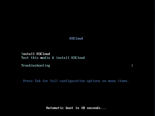
3. Select Install H3Cloud (selected by default), and then press Enter. If only one local disk is available and no data exists on the disk, you enter the INSTALLATION SUMMARY page directly. If multiple local disks are available and data exists on the disks, you must complete the required tasks and then you enter the INSTALLATION SUMMARY page. For more information, see "What should I do when the system prompts "WARNING, Which of the detected hard drivers do you want to be used as the installation target?”?."
|
|
CAUTION: · You can configure only the system disk. CloudOS partitions the system disk automatically. Do not change the partitions manually. · To avoid operating system boot failure, you must select the first disk as the system disk, sda for example. |
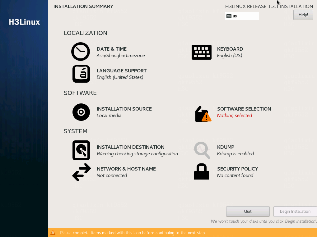
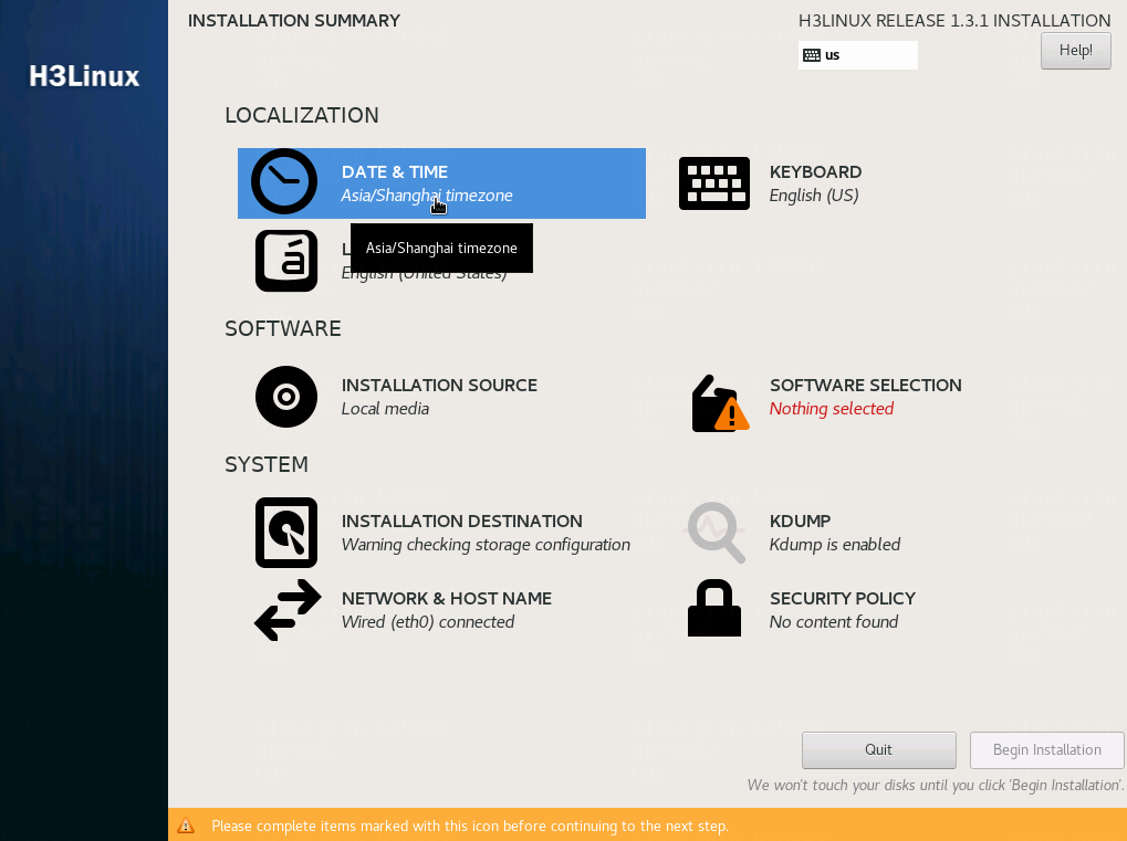
4. Configure SOFTWARE SELECTION and NETWORK&HOST NAME as required.
|
|
CAUTION: To avoid CloudOS deployment failure, do not configure any parameters other than SOFTWARE SELECTION and NETWORK&HOST NAME. |
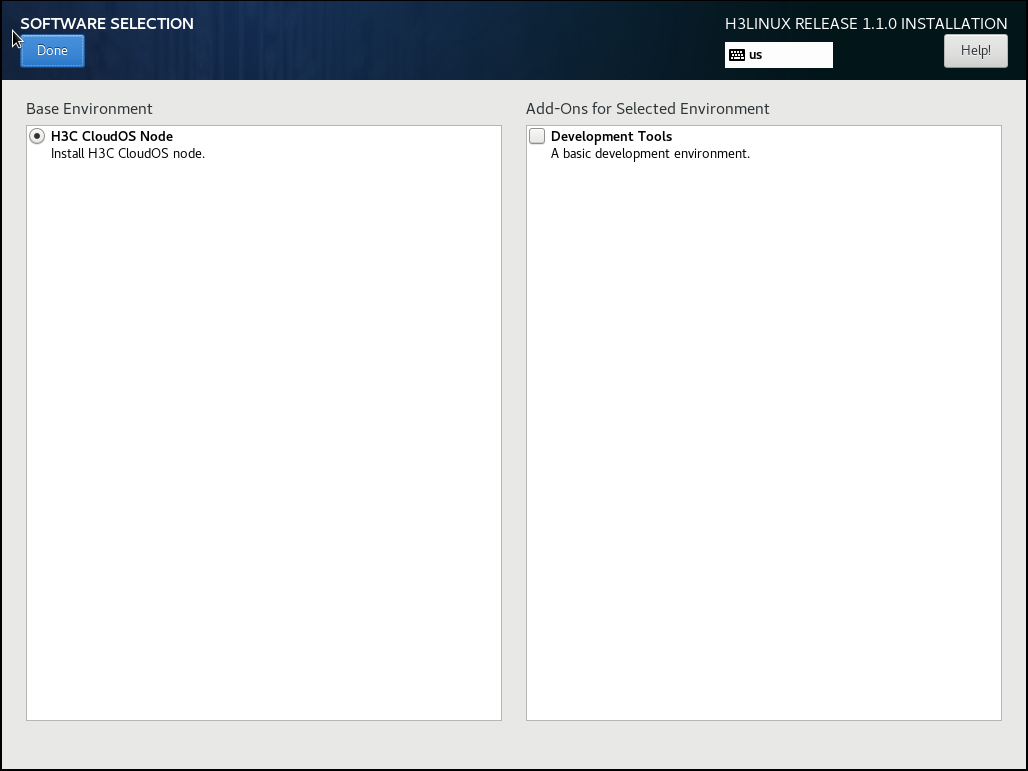
5. To select software, click SOFTWARE SELECTION, and then select H3C CloudOS Node. Click Done in the upper left corner to return to the INSTALLATION SUMMARY page.
You can select Development Tools as needed to install build tools such as GCC and Kernel-develop. If a CloudAI service exists, you must select it.
Figure 5 Selecting the software
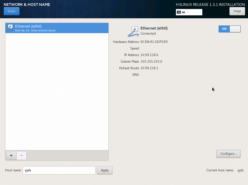
6. To configure the network and host name, click NETWORK & HOST NAME.
Figure 6 Network and host name
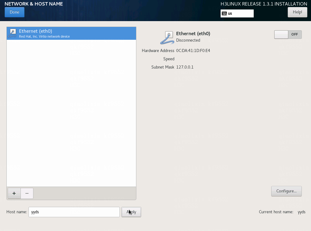
a. Enter the host name in the Host name field, and then click Apply.
Make sure the host names of the controller nodes are different in cluster mode and do not contain the following strings: controller, masters, worker, master, new_nodes, etcd, nodes, new_masters. A host name can contain lower-case letters or digits, and must start with a lower-case letter. It can contain minus signs (-) and dots (.).
After you modify the host name, click Apply and verify the host name displayed in the Current host name field.
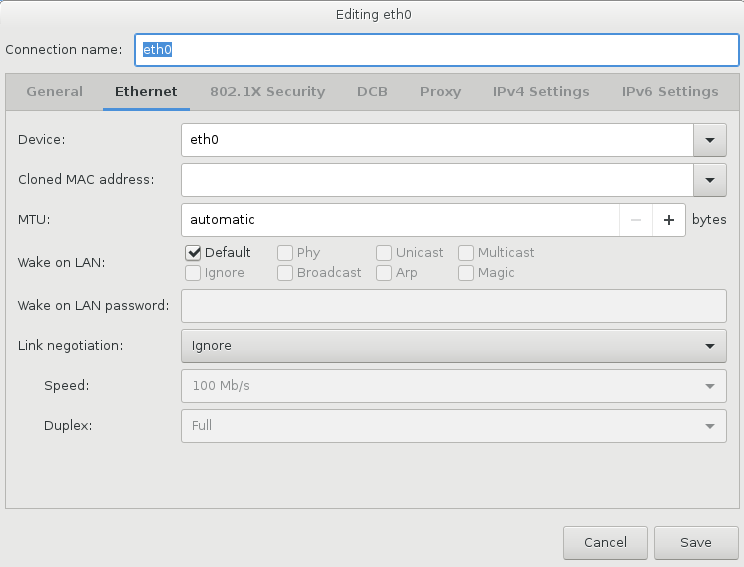
b. Select the NIC to which the management network connects, and then click Configure.
|
|
CAUTION: As a best practice, do not change the default connection name. A connection name must start with the letter e. |
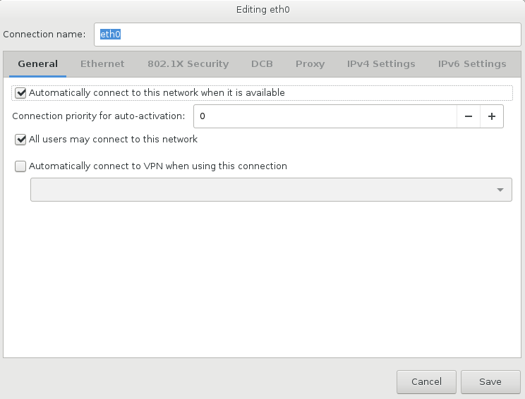
c. Click the General tab, and then select Automatically connect to this network when it is available.
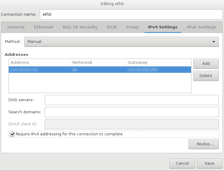
d. Click the IPv4 Settings tab, select Manual from the Method list, click Add, configure an IPv4 address, mask, and gateway, select Require IPv4 addressing for this connection to complete, and then click Save.
|
|
IMPORTANT: · To avoid deployment failure, use the same NIC for the management network and cluster and specify a gateway address for the NIC. If you use multiple NICs, configure only one gateway. If no gateway exists, configure a virtual gateway address. · Only IPv4 addresses are supported. · If you cannot save the IPv4 address configuration, remove the configuration and try again. |
e. (Optional.) Configure a storage NIC. A storage network and management network can share the same NIC. If you have planned an independent storage network, install a storage NIC on the server and configure the storage network in the same way the management network is configured.
f. Click Done in the upper left corner.
Set the network connection state to ON after network configuration is completed.
Figure 10 NIC configuration completed
7. Verify that all required configuration is completed, and then click Begin Installation.
Figure 11 Configuration completed
8. Wait for the server to be installed.
Figure 12 Installing the server

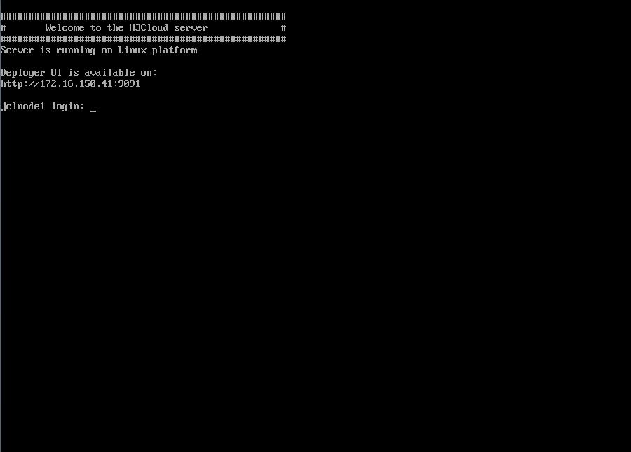
Reboot completed
|
|
NOTE: · The default username and password are root and Passw0rd@_ respectively. · Do not change the password before you complete deploying CloudOS. |
9. (Optional.) Configure NIC bonding for the controller nodes as described in "Configuring NIC bonding."
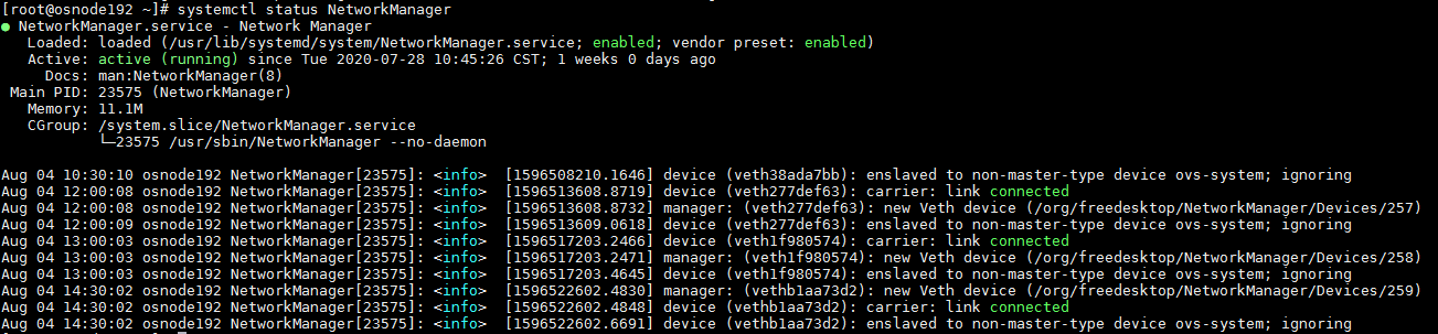
10. To avoid deployment failure, execute the systemctl status NetworkManager command to verify that the NetworkManager service operates correctly. If the NetworkManager is not operating correctly, execute the systemctl enable NetworkManager and systemctl start NetworkManager commands.
Figure 14 Enabling the NetworkManager service
11. Repeat steps 1 through 10 to install CloudOS on the other nodes.
(Optional.) Editing the parameters for a Huawei 2488H V5 or 2288H V5 server on the installation method selection screen
A black screen issue might occur if you install CloudOS on a Huawei 2488H V5 or 2288H V5 server. To avoid this issue, edit the parameters as follows after entering the installation method selection screen.
· In UEFI mode, press e after entering the installation method selection screen, add inst.graphical inst.xdriver=fbdev video=efifb:off video=VGA-1:1024x768-32@60me ro console=tty0 to the end of the linuxefi or linux line, and then press Ctrl + X.
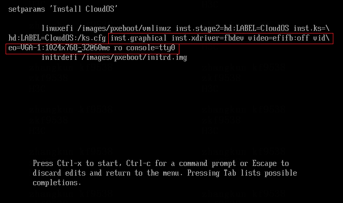
· In legacy mode, press Tab after entering the installation method selection screen, add inst.graphical inst.xdriver=fbdev video=efifb:off video=VGA-1:1024x768-32@60me ro console=tty0 to the end of the vmlinuz line, and then press Enter.

Deploying CloudOS components
If NIC bonding is required, configure NIC bonding as described in "Configuring NIC bonding" before you deploy CloudOS components.
If NIC offload is enabled, execute the ethtool -K ethX rx off tx off sg off tso off command on all nodes to disable NIC offload for all NICs. ethX represents the NIC name.
After you install CloudOS servers, use GoMatrix to deploy CloudOS nodes.
Deploying CloudOS
Install an operating system for all nodes before deploying CloudOS. For more information, see "Installing CloudOS servers."
The node from which you log in to GoMatrix will act as the master node.
The default username and password are root and Passw0rd@_, respectively. Do not change the password before you complete deploying CloudOS.
Logging in to GoMatrix
1. Launch a browser, and then enter http://<management IP of the master node>:9091 in the address bar.
Figure 15 Logging in to GoMatrix
2. Enter the default username admin and password Passw0rd@_, and then click Log In.
Figure 16 Homepage
Deploying a node
1. On the top navigation bar, click Deploy. On the Basic Settings page that opens, configure the cluster VIP, management VIP, NTP service address, and language, and then click Next. Make sure the VIPs are the same.
¡ Cluster VIP—Virtual IP address of the CloudOS cluster network. It is used for internal communication between nodes in a cluster and you can choose to not expose it to the external network.
¡ Management VIP—Virtual IP address of the CloudOS management network. It is used for logging in to the CloudOS management page.
¡ NTP Service Address—By default, the NTP service address is the management IP address of the master node. To specify an external NTP server, enter the external NTP server address. If you do not use an external NTP server, make sure the system time of the master node time is the same as the local standard time.
¡ Language—By default, the system language is Chinese. If you select English, the alarm names of the default alarm rules and the Grafana page after CloudOS setup are displayed in English.
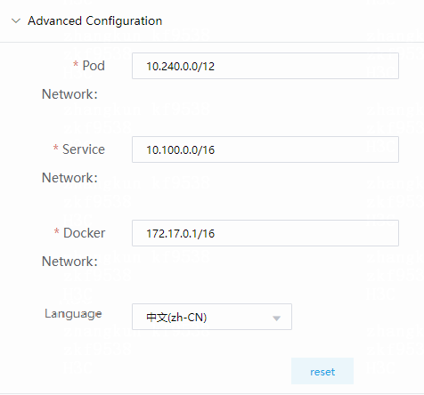
¡ Subnets 10.100.0.0/16, 10.240.0.0/12, and 172.17.0.1/16 are reserved. Do not use IP addresses in these subnets. If your networks overlap with these subnets, click Advanced Configuration to edit the subnets, and then click Next.
Figure 17 Basic Settings page
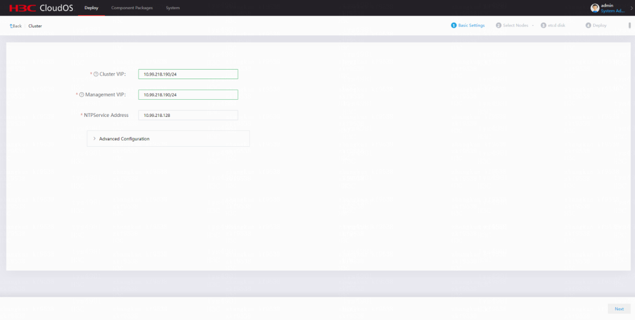
Figure 18 Advanced Configuration page
2. Enter the IP address, username, and password of the cluster node in the Select Nodes area, and then click Add. As a best practice, add three or five nodes to the cluster.
|
|
CAUTION: · Make sure the management network IP addresses of the nodes in the cluster can reach each other and are in the same subnet. · Make sure the system time of the node to be added is the same as that of the master node. If the time offset is more than 10 seconds between the node to be added and the master node, you will fail to add the new node. |
Figure 19 Adding a cluster node
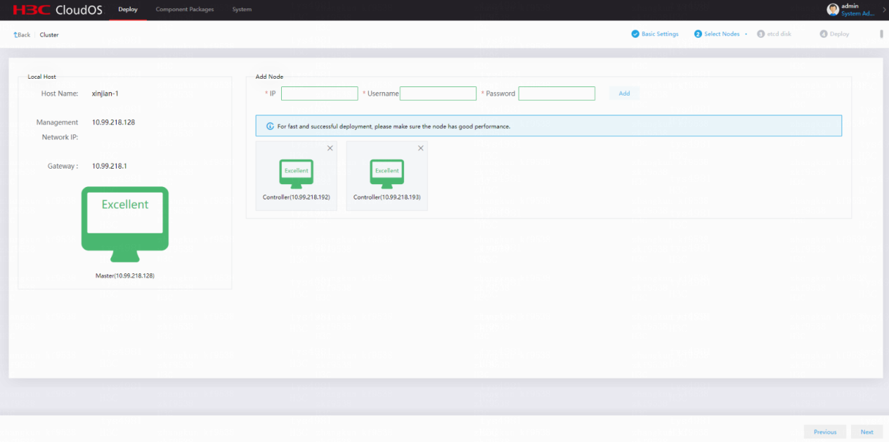
The system automatically checks the local host to determine whether it has enough resources for deployment. If the check result is excellent or good, you can continue deployment. If the check result is fair or poor, verify that the specifications of the server meet the requirements in "System requirements" before deployment.
3. Configure etcd disk settings:
|
|
IMPORTANT: · Each CloudOS controller node requires two dedicated disks for etcd. As a best practice, use SSDs for the controller nodes. To avoid etcd node data inconsistency and cluster failures, do not use shared disks for etcd or assign the partitions of a disk to multiple etcds. · Configure RAID correctly for disks before deployment and use the first disk of the ones configured with RAID as the system disk on each server. Set up RAID 0 on the two data disks. · The etcd disk capacity must be in the range of 100 GB to 1 TB. · You can perform an IO benchmark test on the two disks before configuration. For more information, see "How do I perform a disk IO benchmark test before node deployment." |
etcd is the underlying distributed database of the core components in CloudOS. It saves and updates state information about the CloudOS cluster.
a. Select one host.
Figure 20 Selecting one host
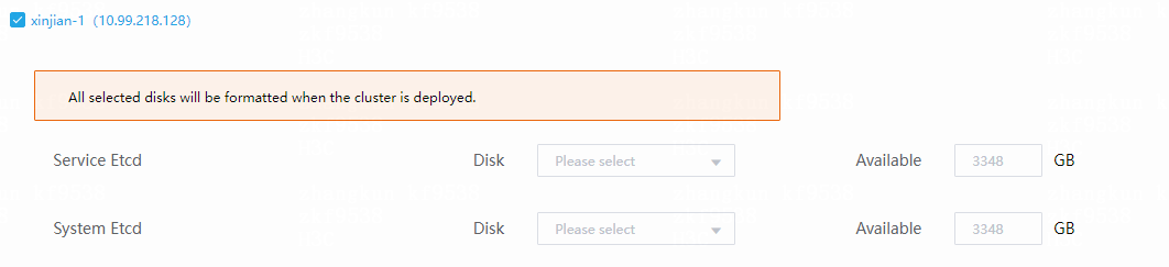
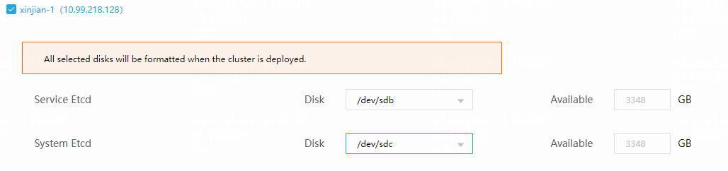
b. Select disks.
Figure 21 Selecting disks
|
|
IMPORTANT: · etcd requires dedicated disks in production environments. In non-production environments, you can use system disks for etcd but you must ensure that the system disks have high performance. · To deploy GlusterFS in DataEngine E-MapReduce big data deployment scenarios, do not select disk sdb for etcd. Disk sdb is reserved for GlusterFS. |
d. Select the three nodes and disks, and then click Next.
|
|
IMPORTANT: · If you do not select disks, etcd uses the system disk. · If you have selected wrong disks during the operation, see "What should I do if I select a wrong etcd node during node deployment." |
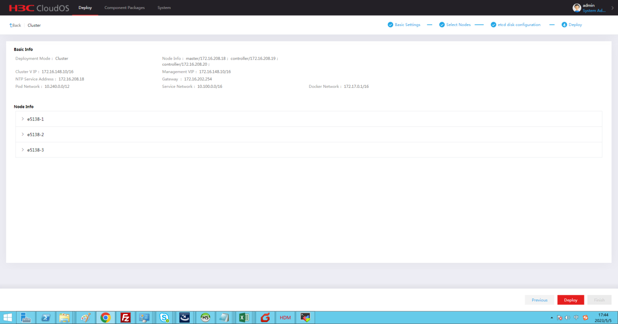
4. On the page that opens, review the basic information, node information, and etcd information, and then click Deploy. To edit the configuration, click Previous to return to the previous step.
Figure 22 Reviewing information
5. Start deploying CloudOS.
Figure 23 Deployment in progress
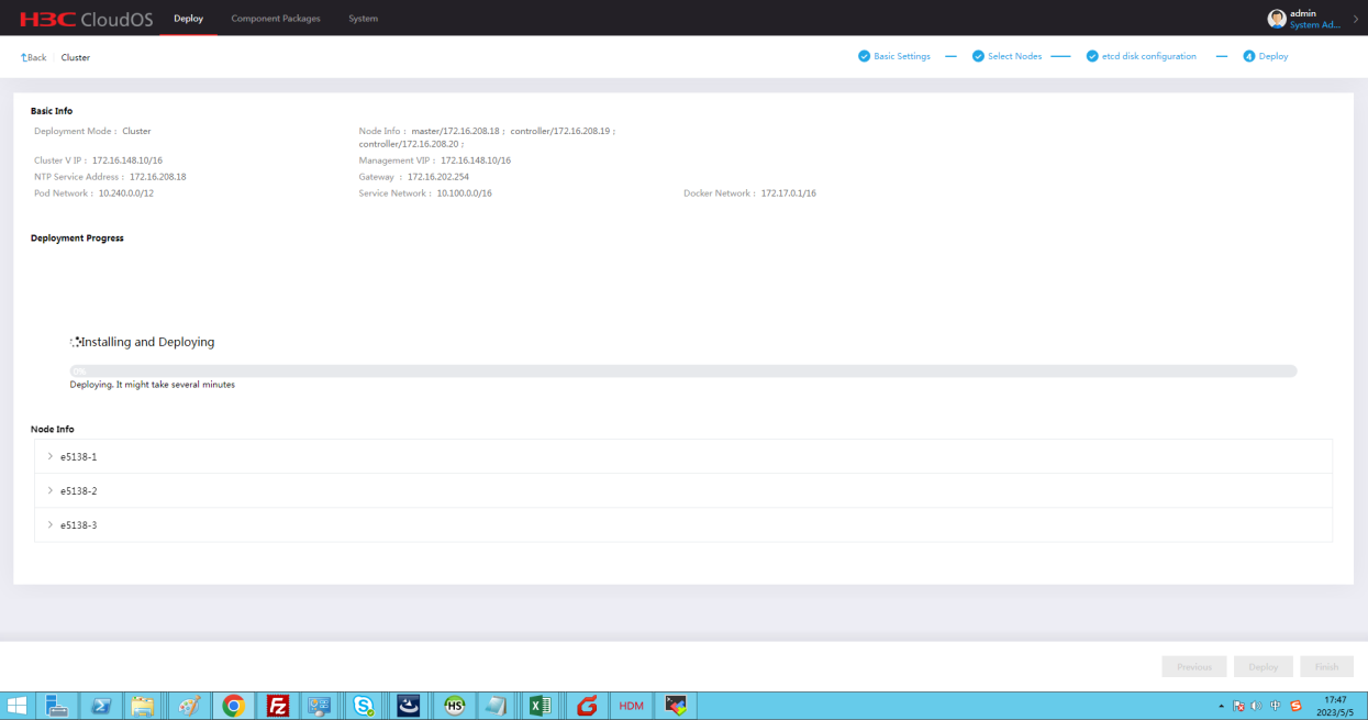
|
|
NOTE: Typically, the deployment takes about an hour. In some environments with poor performance, the deployment takes a longer time. The deployment progress might stop at 66% for a long time. Please wait. If you are logged off because of page timeout, open the browser and access Gomatrix again. On the page that opens, you can see the deployment progress and result. |
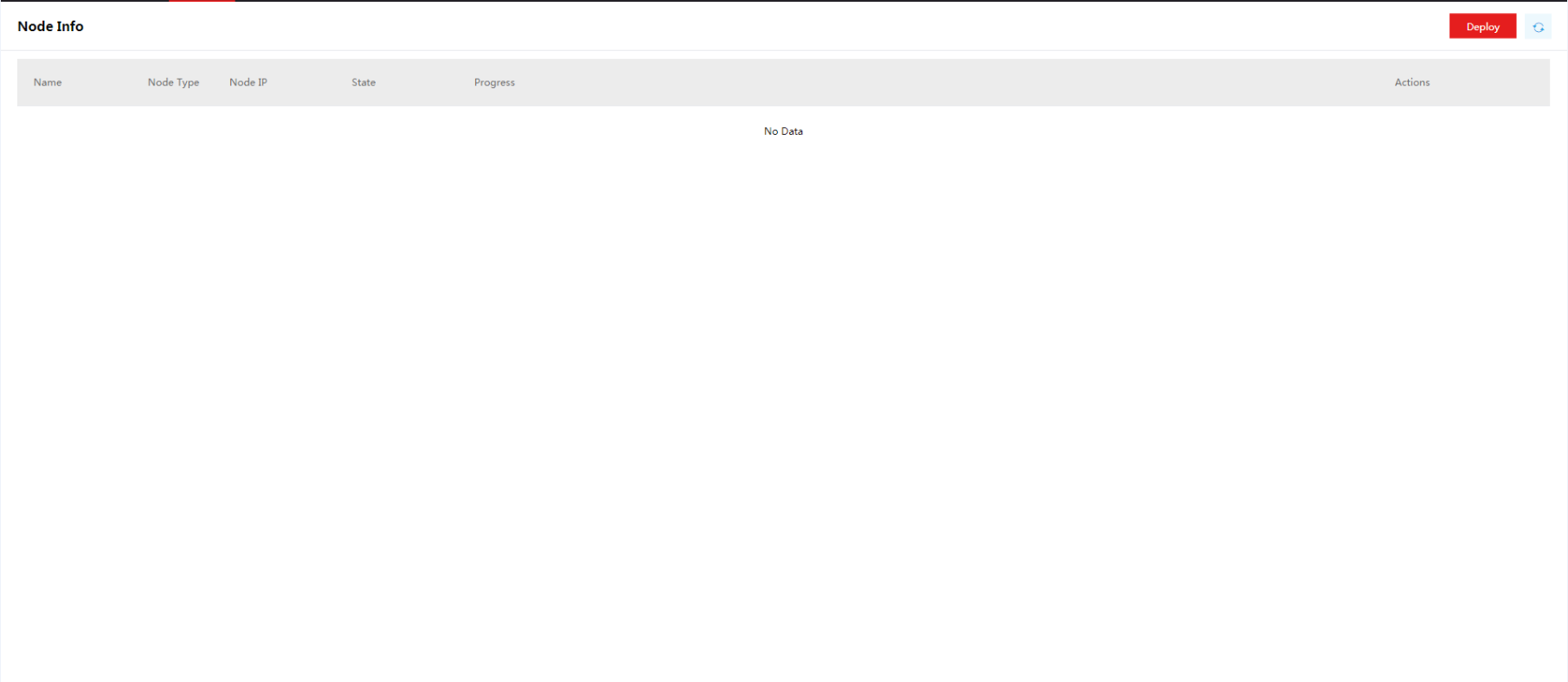
6. Wait for the deployment to finish. You can view detailed deployment information on the Node Info page.
Figure 24 Viewing detailed deployment information

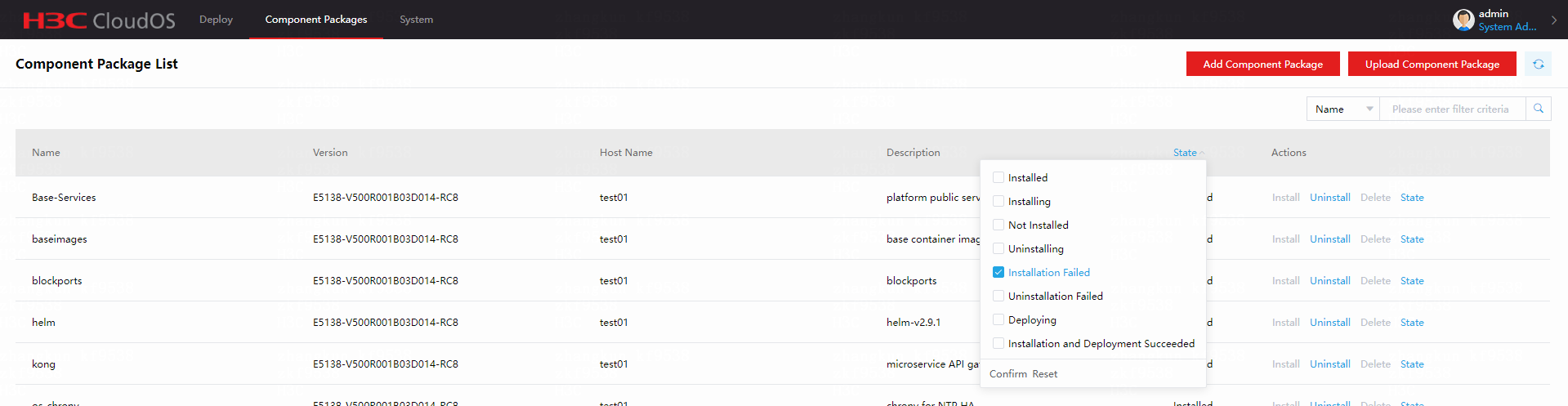
7. Check component deployment results on the package list.
If deployment fails for some components, contact H3C Support.
Figure 25 Component deployment results
8. Check the pre-installed component state on the deployment page. Verify that all components are in normal state.
If installation fails for some components, contact H3C Support.
If no component deployment failure or script execution failure occurs, deployment is successful.
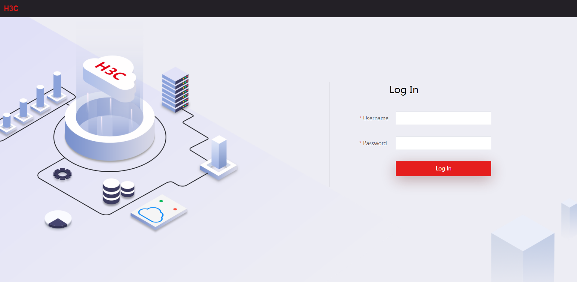
Logging in to CloudOS
1. Launch a browser, and then enter http://CloudOS 5.0_virtual service ip_address in the address bar.
Figure 26 Logging in to CloudOS
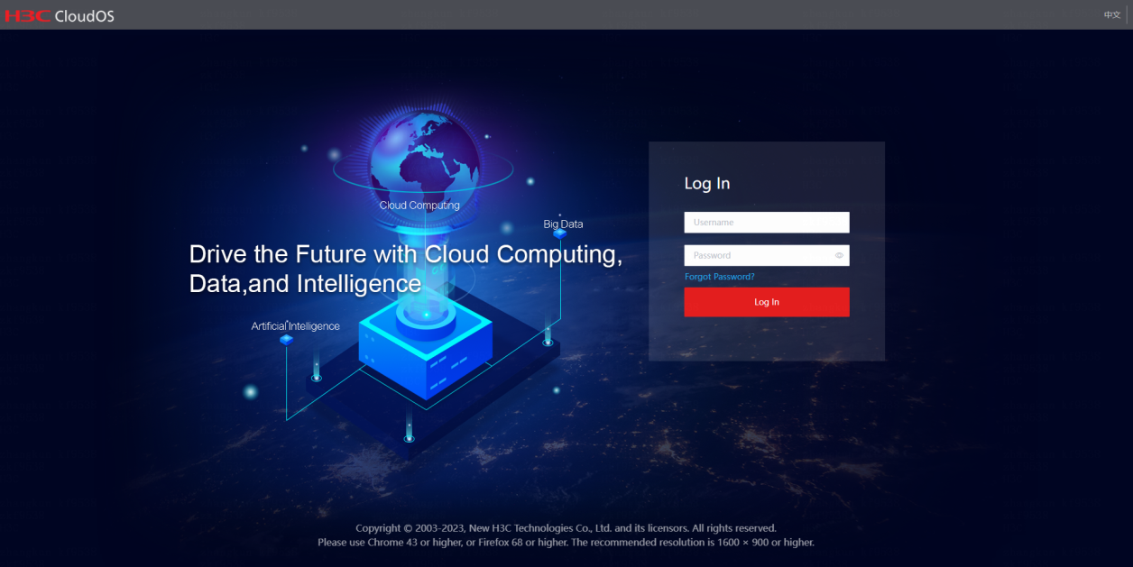
2. Enter the default username admin and password Passw0rd@_, and then click Log In.
Connecting to shared storage
You must configure shared storage for the Harbor and Nexus components before deploying cloud services and system components. Deploy cloud services and system components after you deploy the cluster.
Connecting to ONEStor RBD storage
About ONEStor RBD storage
RADOS Block Device (RBD) is a commonly used storage method provided by ONEStor. CloudOS provides a block-based storage solution for containers through ONEStor RBD.
Before using ONEStor RBD, run the corresponding scripts on the CloudOS nodes.
Configuration requirements
Server requirements
See "System requirements."
Software requirements
ONEStor version: ONEStor-E3115P01.
By default, you can connect CloudOS to ONEStor E3115P01. To connect to ONEStor in another version, contact the ONEStor department to obtain the ONEStor rbd-client of that version.
Network diagram
ONEStor provides RBD-based storage services, and CloudOS provides persistent storage for containers by mounting RBD to the containers through the ONEStor client.
Figure 27 Logical topology
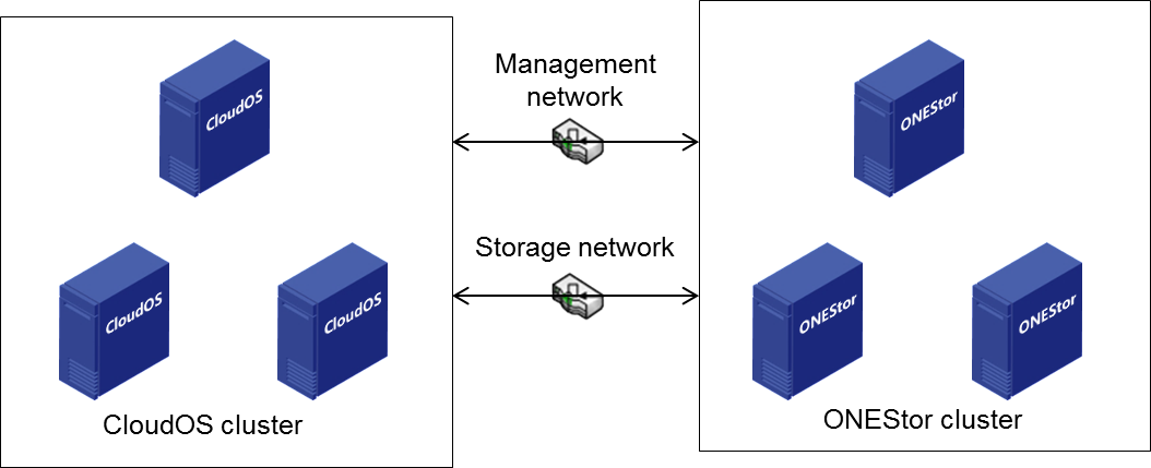
|
|
CAUTION: In actual deployment, follow these guidelines: · Make sure the CloudOS cluster management network and ONEStor cluster management network can reach each other. · Make sure the CloudOS cluster storage network and ONEStor storage front-end network can reach each other. |
Configuring ONEStor cluster files on CloudOS servers
Configuration before deploying cloud services and system components
Log in to the master node in the CloudOS cluster from the CLI and perform the following tasks:
1. Configure the ONEStor server end:
a. Access /opt/onestor-config/get-onestor-info.sh to configure the monitor IP address and the username and password used to log in to the back end of ONEStor.
onestor_ip=10.125.41.234
onestor_username=root
onestor_password=Admin@123stor
b. Edit the location of the ONEStor storage system configuration file. Verify that the configuration file exists on the ONEStor server. The configuration file is stored in the following path by default:
onestor_keyring=/etc/ceph/ceph.client.admin.keyring //ceph.client.admin.keyring absolute path
onestor_conf= /etc/ceph/ceph.conf //ceph.conf absolute path
2. Configure the CloudOS host file.
Host file path: /opt/onestor-config/inventory/inventory.yml.
The configuration template is as follows:
all:
hosts:
node145: #CloudOS host name, which must be the same as the actual host
name.
ansible_host: 10.125.30.145 # The IP address, access_IP, and IP address
must be consistent
access_ip: 10.125.30.145
ip: 10.125.30.145
ansible_ssh_user: root #CloudOS host username
ansible_ssh_pass: Passw0rd@_ #CloudOS host password
node146:
ansible_host: 10.125.30.146
access_ip: 10.125.30.146
ip: 10.125.30.146
ansible_ssh_user: root
ansible_ssh_pass: Passw0rd@_
node147:
ansible_host: 10.125.30.147
access_ip: 10.125.30.147
ip: 10.125.30.147
ansible_ssh_user: root
ansible_ssh_pass: Passw0rd@_
children:
onestor:
hosts:
node145: #Host name followed by a colon
node146:
node147:
3. Run the start.sh script.
Enter the /opt/onestor-config/ directory and execute the sh start.sh command to run the start.sh script.
When a large number of nodes are involved, it takes a long time for ansible to collect the basic data of the nodes and the system will display "TASK[Gathering Facts]". To resolve this issue, add the following configuration in the /opt/onestor-config/config-ceph.yml script:
The following is the existing configuration in the script:
- hosts: onestor
roles:
- { role: onestor-config }
Add the following configuration to the script to cancel node information collection:
- hosts: localhost
gather_facts: false
4. Verify the configuration.
Enter the /etc/ceph directory of a CloudOS node to verify that the following files exist.
ceph.client.admin.keyring
ceph.conf
Node configuration
You can configure nodes before or after CloudOS component deployment. To connect the node to ONEStor RBD storage after deploying the CloudOS component, log in to the CloudOS master node from the CLI and perform the following tasks:
1. Verify that the CloudOS nodes have the same password, which is Passw0rd@_ by default. If the passwords of the nodes are different, edit the password in the /opt/onestor-config/gen_host.sh file:
os_node_password=Passw0rd@_
2. Edit the --limit node1,node2 field in the /opt/onestor-config/add-node.sh script.
node1,node2 represents the host names. You can add multiple host names separated by commas (,). For example, to add host worker1, set this field to --limit worker1.
3. Access the /opt/onestor-config/ directory and execute the following command:
Replace worker1 with the host name of the node.
ansible worker1 -i ./inventory/inventory.yml -m ping -vvv
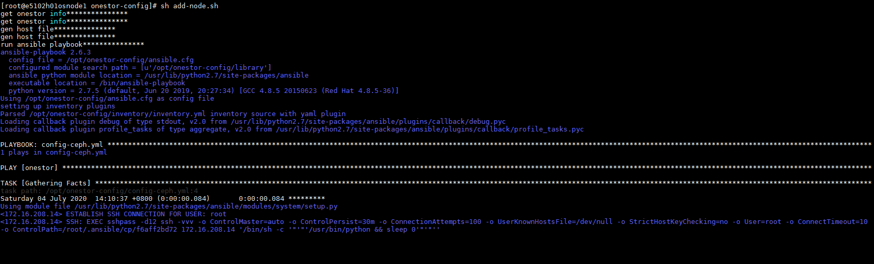
4. Access the /opt/onestor-config directory and run the sh add-node.sh script.
If the script stops as shown in Figure 28, press Ctrl + C, execute the ansible worker1 -i ./inventory/inventory.yml -m ping -vvv command, and then run the sh add-node.sh script.
Figure 28 Running the sh add-node.sh script
5. Verify the configuration.
Access the /etc/ceph directory of the node to verify that the following files exist:
ceph.client.admin.keyring
ceph.conf
6. Repeat the previous steps to configure other nodes.
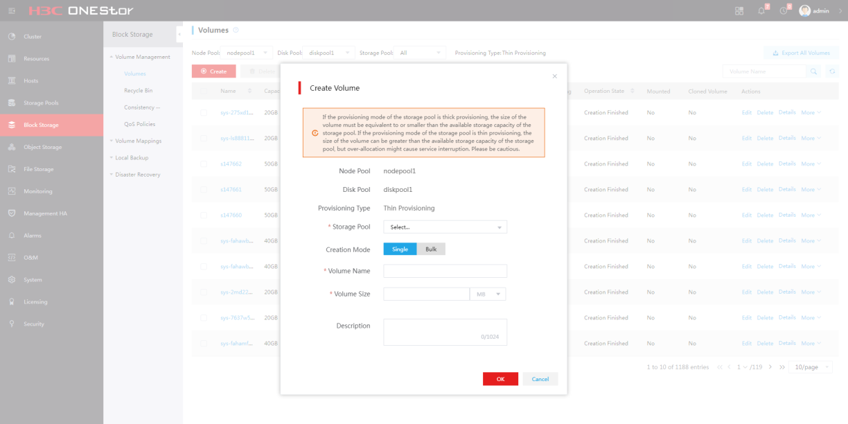
Creating a storage volume on ONEStor
1. Log in to ONEStor.
2. From the navigation pane, select Block Storage > Volume Management.
3. Create a shared storage volume for the platform and the cloud services.
Configure the storage volume name as the name of the image used in ceph shared storage configuration. For more information, see the ONEStor manual.
Figure 29 Creating a storage volume on ONEStor
Connecting to iSCSI storage
Restrictions and guidelines
Associate each controller node with storage.
When you configure multipathing, enable the ALUA mode on the storage side.
For CloudOS to recognize and add an iSCSI storage volume successfully, make sure the storage volume IQN is in the iqn.yyyy-mm.naming-authority:unique format. For more information, access https://docs.vmware.com/en/VMware-vSphere/5.5/com.vmware.vsphere.storage.doc/GUID-686D92B6-A2B2-4944-8718-F1B74F6A2C53.html.
Procedure
The server that runs CloudOS uses the CentOS 7.6 operating system. Site engineers can configure storage multipathing by using Linux multipathing or the scheme provided with the storage device.
The procedure is the same for configuring iSCSI single path and multipath. This document uses the multipath configuration as an example.
Perform the following tasks after CloudOS deployment is completed.
To map an iSCSI storage volume:
1. Log in to each controller node and verify that multipathing is enabled.
If multipathing is disabled, execute the systemctl start multipathd.service command to enable it.
[root@cloudos5-9926 ~]# systemctl status multipathd.service
● multipathd.service - Device-Mapper Multipath Device Controller
Loaded: loaded (/usr/lib/systemd/system/multipathd.service; disabled; vendor preset: enabled)
Active: active (running) since Thu 2020-07-23 10:21:21 CST; 14s ago
Process: 11979 ExecStart=/sbin/multipathd (code=exited, status=0/SUCCESS)
Process: 11976 ExecStartPre=/sbin/multipath -A (code=exited, status=0/SUCCESS)
Process: 11971 ExecStartPre=/sbin/modprobe dm-multipath (code=exited, status=0/SUCCESS)
Main PID: 11982 (multipathd)
Memory: 4.0M
CGroup: /system.slice/multipathd.service
└─11982 /sbin/multipathd
Jul 23 10:21:21 cloudos5-9926 systemd[1]: Starting Device-Mapper Multipath Device Controller...
Jul 23 10:21:21 cloudos5-9926 systemd[1]: Started Device-Mapper Multipath Device Controller.
Jul 23 10:21:21 cloudos5-9926 multipathd[11982]: path checkers start up
[root@cloudos5-9926 ~]#
2. Execute the cat /etc/multipath.conf command to view the multipathing configuration file.
[root@cloudos5-9926 ~]# cat /etc/multipath.conf
defaults {
user_friendly_names “yes”
path_checker "tur"
prio "const"
path_grouping_policy "group_by_prio"
no_path_retry 25
max_fds "max"
failback "immediate"
}
blacklist {
wwid ".*"
}
blacklist_exceptions {
property "(ID_SCSI|ID_WWN)"
}
[root@cloudos5-9926 ~]#
|
|
NOTE: To edit the multipath.conf configuration file, contact the storage device vendor. The values for the configuration items vary depending on the vendor. You can copy and paste the configuration file to the corresponding path on another node. |
3. Log in to the operating system of each controller node, and then execute the following command and record the information. You can edit the initiatorname.iscsi file as required. Restart iscsid.service to have the edit take effect.
[root@h3cloud01 ~]# cat /etc/iscsi/initiatorname.iscsi
InitiatorName=iqn.1994-05.com.redhat:84881052e83e
4. Create storage volumes on the storage device, and configure the mappings between the servers and storage volumes. For more information, see the user guide for the storage device.
5. Map and discover storage volumes.
[root@cloudos5-9925 ~]# iscsiadm -m discovery -t sendtargets -p 172.100.1.235
172.100.1.235:3260,12 iqn.2006-08.com.huawei:oceanstor:2100c0bfc0a8d488::1020001:172.100.1.235
[root@cloudos5-9925 ~]# iscsiadm -m node -l
Logging in to [iface: default, target: iqn.2006-08.com.huawei:oceanstor:2100c0bfc0a8d488::1020001:172.100.1.235, portal: 172.100.1.235,3260] (multiple)
Login to [iface: default, target: iqn.2006-08.com.huawei:oceanstor:2100c0bfc0a8d488::1020001:172.100.1.235, portal: 172.100.1.235,3260] successful.
[root@cloudos5-9925 ~]#
[root@cloudos5-9925 ~]# iscsiadm -m discovery -t sendtargets -p 172.99.1.235
172.99.1.235:3260,2 iqn.2006-08.com.huawei:oceanstor:2100c0bfc0a8d488::20001:172.99.1.235
[root@cloudos5-9925 ~]# iscsiadm -m node -l
Logging in to [iface: default, target: iqn.2006-08.com.huawei:oceanstor:2100c0bfc0a8d488::20001:172.99.1.235, portal: 172.99.1.235,3260] (multiple)
Login to [iface: default, target: iqn.2006-08.com.huawei:oceanstor:2100c0bfc0a8d488::20001:172.99.1.235, portal: 172.99.1.235,3260] successful.
[root@cloudos5-9926 ~]#
6. View the storage connection state, IP paths, LUNs, and drive letters.
Figure 30 Viewing the storage connection state, IP paths, LUNs, and drive letters
7. Obtain the storage volume WWIDs through drive letters.
Figure 31 Obtaining the storage volume WWIDs

8. Edit the multipath.conf file on all controller nodes. Add WWIDs of the volumes that are enabled with multipathing to blacklist exceptions.
[root@cloudos5-9926 ~]# cat /etc/multipath.conf
defaults {
user_friendly_names “yes”
path_checker "tur"
prio "const"
path_grouping_policy "group_by_prio"
no_path_retry 25
max_fds "max"
failback "immediate"
}
blacklist {
wwid ".*"
}
blacklist_exceptions {
property "(ID_SCSI|ID_WWN)"
wwid "36c0bfc0100a8d4888e0b141a00000015"
wwid "36c0bfc0100a8d4888e0b331500000017"
wwid "36c0bfc0100a8d4888e0b4e3900000060"
wwid "36c0bfc0100a8d4888e0b64e30000006a"
wwid "36c0bfc0100a8d4880d627cf700000074"
wwid "36c0bfc0100a8d4880d62923300000075"
}[root@cloudos5-9926 ~]#
9. Restart the multipathing service.
[root@cloudos5-9926 ~]# systemctl restart multipathd.service
10. View multipathing information.
[root@h3cloud01 ~]# multipath -ll
mpathe (360003ff44dc75adcbe7175fce8bece20) dm-6 MSFT ,Virtual HD
size=50G features='1 queue_if_no_path' hwhandler='0' wp=rw
`-+- policy='round-robin 0' prio=1 status=active
|- 3:0:0:0 sdct 8:0 active ready running
`- 17:0:0:0 sdcw 8:220 active ready running
mpathd (360003ff44dc75adcaf5a6d7b5389d9d9) dm-2 MSFT ,Virtual HD
size=50G features='1 queue_if_no_path' hwhandler='0' wp=rw
`-+- policy='round-robin 0' prio=1 status=active
|- 18:0:0:0 sdh 8:236 active ready running
`- 4:0:0:0 sdp 8:16 active ready running
...
11. (Optional.) Format storage volumes.
After obtaining the storage volume multipath names, you format the storage volumes by executing corresponding commands on one node.
For a new deployment, you must format the storage volumes on the iSCSI storage device and make sure the file system is in ext4 format. For more information, see "Formatting storage volumes."
12. Deploy cloud services and system components after configuration on all nodes is completed.
Connecting to FC storage
In the current CloudOS version, multipathing is required in FC storage single path and multipath scenarios.
When you configure FC multipathing, enable the ALUA mode on the storage side.
The server that runs CloudOS uses the CentOS 7.6 operating system. Site engineers can configure storage multipathing by using Linux multipathing or the scheme provided with the storage device.
Connecting to FC storage in single-path mode
|
|
CAUTION: The section applies to the scenarios where the deployment environment provides only one path. You must configure multipathing settings for connecting to FC storage in single-path mode. |
To connect to FC storage in single-path mode:
1. Log in to the operating system of the master node. Mount the storage volumes and execute the following commands:
[root@h3cloud01 ~]# modprobe dm_multipath
[root@h3cloud01 ~]# modprobe dm-round-robin
2. Execute the following command to enable multipathing:
[root@h3cloud01 ~]# systemctl start multipathd.service
3. Map the storage volumes.
Log in to the operating system of each controller node, and then execute the following command to display the WWNs of online FC interfaces and record the information.
The value of X depends on the specifications of the storage NICs. WWN is the string following 0x, which is 10000090fa40a551 in this example.
[root@h3cloud01 ~]#cat /sys/class/fc_host/hostX/port_state
Online
[root@h3cloud01 ~]# cat /sys/class/fc_host/hostX/port_name
0x10000090fa40a551
4. Create storage volumes on the storage device, and configure the mappings between the servers and storage volumes. For more information, see the user guide for the storage device.
5. Discover storage volumes. Log in to the operating system of each controller node, and then execute the following command to discover storage volumes. The value of X depends on the specifications of the storage NICs.
[root@h3cloud01 ~]# echo "1" > /sys/class/fc_host/hostX/issue_lip
6. Execute the ls –l /dev/disk/by-path command to obtain the drive letters of the FC storage volumes.
Figure 32 Obtaining drive letters
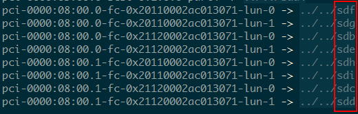
|
|
CAUTION: The drive letters vary by nodes, but the WWN and LUN number (x) combination in fc-0x[WWN]-lun-[x] is the same on each node. |
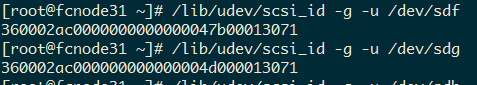
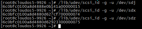
7. Execute the following command to obtain and record the storage volume WWIDs through the drive letters:
/lib/udev/scsi_id -g -u /dev/[drive letter]
Figure 33 Obtaining storage volume WWIDs
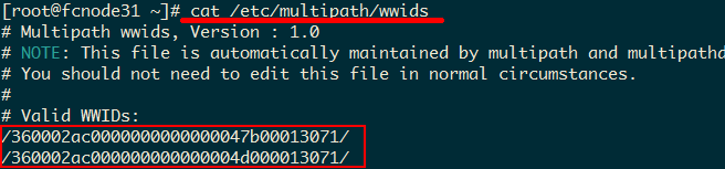
8. Write the WWIDs and alias into the wwids file.
Figure 34 Writing WWIDs into the wwids file
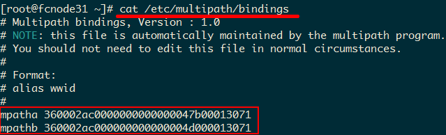
9. Write the WWIDs and alias into the bindings file.
Figure 35 Writing WWIDs into the bindings file
10. Edit the multipath.conf file on all controller nodes. Add WWIDs of the volumes that are enabled with multipathing to blacklist exceptions.
[root@cloudos5-9926 ~]# cat /etc/multipath.conf
blacklist {
wwid ".*"
}
blacklist_exceptions {
property "(ID_SCSI|ID_WWN)"
wwid "36c0bfc0100a8d4888e0b141a00000015"
wwid "36c0bfc0100a8d4888e0b331500000017"
wwid "36c0bfc0100a8d4888e0b4e3900000060"
wwid "36c0bfc0100a8d4888e0b64e30000006a"
wwid "36c0bfc0100a8d4880d627cf700000074"
wwid "36c0bfc0100a8d4880d62923300000075"
}
defaults {
user_friendly_names “yes”
path_checker "tur"
prio "const"
path_grouping_policy "group_by_prio"
no_path_retry 25
max_fds "max"
failback "immediate"
}
[root@cloudos5-9926 ~]#
11. Restart the multipathing service.
[root@cloudos5-9926 ~]# systemctl restart multipathd.service
12. Execute the multipath -r command to refresh information about the multipathing volumes.
Figure 36 Refreshing information about the multipathing volumes
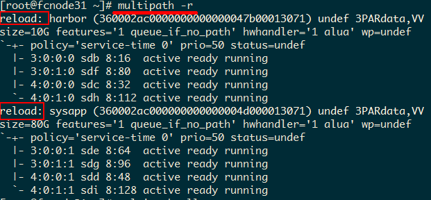
In this example, the first volume multipath name is mpathe, which has two paths. The drive letters are sda and sdb.
[root@h3cloud01 ~]# multipath -ll
mpathe (360003ff44dc75adcbe7175fce8bece20) dm-6 MSFT ,Virtual HD
size=50G features='1 queue_if_no_path' hwhandler='0' wp=rw
`-+- policy='round-robin 0' prio=1 status=active
|- 3:0:0:0 sda 8:0 active ready running
mpathd (360003ff44dc75adcaf5a6d7b5389d9d9) dm-2 MSFT ,Virtual HD
size=50G features='1 queue_if_no_path' hwhandler='0' wp=rw
`-+- policy='round-robin 0' prio=1 status=active
|- 18:0:0:0 sdb 8:236 active ready running
...
13. Execute the ll /dev/disk/by-path | grep sda command to obtain the LUN for the first volume, which is 0. Find the lun-0 volume created on the storage side. Select the multipath name according to the relations in the subsequent deployment.
14. (Optional.) Format storage volumes.
After obtaining the storage volume multipath names, you format the storage volumes by executing corresponding commands on one node.
For a new deployment, you must format the storage volumes on the FC storage device and make sure the file system is in ext4 format. For more information, see "Formatting storage volumes."
15. Deploy cloud services and system components after configuration on all nodes is completed.
Connecting to FC storage in multipathing mode
1. Log in to the operating system of the master node. Mount the storage volumes and execute the following commands:
[root@h3cloud01 ~]# modprobe dm_multipath
[root@h3cloud01 ~]# modprobe dm-round-robin
2. Execute the cat /etc/multipath.conf command to view the multipathing configuration file.
[root@cloudos5-9926 ~]# cat /etc/multipath.conf
blacklist {
wwid ".*"
}
blacklist_exceptions {
property "(ID_SCSI|ID_WWN)"
}
defaults {
user_friendly_names “yes”
path_checker "tur"
prio "const"
path_grouping_policy "group_by_prio"
no_path_retry 25
max_fds "max"
failback "immediate"
}
[root@cloudos5-9926 ~]#
3. Execute the following command to enable multipathing:
[root@h3cloud01 ~]# systemctl start multipathd.service
4. View the multipathing state.
[root@cloudos5-9926 ~]# systemctl status multipathd.service
● multipathd.service - Device-Mapper Multipath Device Controller
Loaded: loaded (/usr/lib/systemd/system/multipathd.service; disabled; vendor preset: enabled)
Active: active (running) since Thu 2020-07-23 10:21:21 CST; 14s ago
Process: 11979 ExecStart=/sbin/multipathd (code=exited, status=0/SUCCESS)
Process: 11976 ExecStartPre=/sbin/multipath -A (code=exited, status=0/SUCCESS)
Process: 11971 ExecStartPre=/sbin/modprobe dm-multipath (code=exited, status=0/SUCCESS)
Main PID: 11982 (multipathd)
Memory: 4.0M
CGroup: /system.slice/multipathd.service
└─11982 /sbin/multipathd
Jul 23 10:21:21 cloudos5-9926 systemd[1]: Starting Device-Mapper Multipath Device Controller...
Jul 23 10:21:21 cloudos5-9926 systemd[1]: Started Device-Mapper Multipath Device Controller.
Jul 23 10:21:21 cloudos5-9926 multipathd[11982]: path checkers start up
[root@cloudos5-9926 ~]#
|
|
NOTE: To edit the multipath.conf configuration file, contact the storage device vendor. Configuration values depend on the vendor. You can copy and paste the configuration file to the corresponding position on another node. |
5. Map the storage volumes. Log in to the operating system of each controller node, and then execute the following command to display the WWNs of online FC interfaces and record the information.
The value of X depends on the specifications of the storage NICs. WWN is the string following 0x, which is 10000090fa40a551 in this example.
[root@h3cloud01 ~]#cat /sys/class/fc_host/hostX/port_state
Online
[root@h3cloud01 ~]# cat /sys/class/fc_host/hostX/port_name
0x10000090fa40a551
6. Create storage volumes on the storage device, and configure the mappings between the servers and storage volumes. For more information, see the user guide for the storage device.
7. Discover storage volumes. Log in to the operating system of each controller node, and then execute the following command to discover the storage volumes. The value of X depends on the specifications of the storage NICs. If multiple ports on the HBA card of the server connect to the storage, which means that multiple online hosts exist, execute the following command for each host.
[root@h3cloud01 ~]# echo "1" > /sys/class/fc_host/hostX/issue_lip
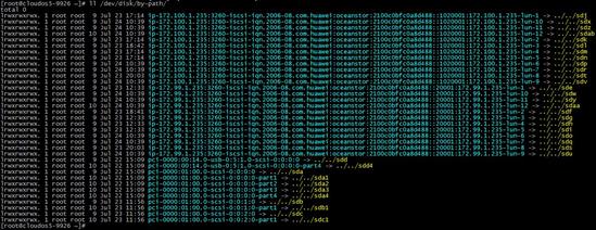
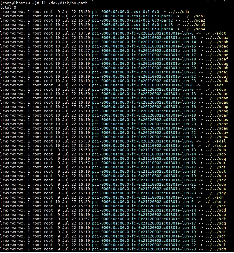
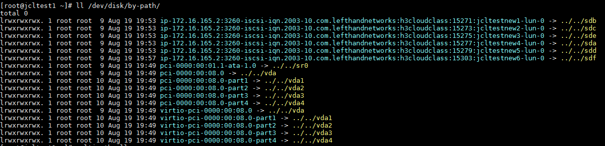
8. Execute the following command to view the storage connection state, volumes, LUNs, and drive letters. The following figure is for your reference only.
[root@h3cloud01 ~]# ll /dev/disk/by-path
Figure 37 Viewing storage connection state
9. Obtain the storage volume WWIDs by using the drive letters.
Figure 38 Obtaining storage volume WWIDs
10. Edit the multipath.conf file on all controller nodes. Add WWIDs of the volumes that are enabled with multipathing to blacklist exceptions.
[root@cloudos5-9926 ~]# cat /etc/multipath.conf
blacklist {
wwid ".*"
}
blacklist_exceptions {
property "(ID_SCSI|ID_WWN)"
wwid "36c0bfc0100a8d4888e0b141a00000015"
wwid "36c0bfc0100a8d4888e0b331500000017"
wwid "36c0bfc0100a8d4888e0b4e3900000060"
wwid "36c0bfc0100a8d4888e0b64e30000006a"
wwid "36c0bfc0100a8d4880d627cf700000074"
wwid "36c0bfc0100a8d4880d62923300000075"
}
defaults {
user_friendly_names “yes”
path_checker "tur"
prio "const"
path_grouping_policy "group_by_prio"
no_path_retry 25
max_fds "max"
failback "immediate"
}
[root@cloudos5-9926 ~]#
11. Restart the multipathing service.
[root@cloudos5-9926 ~]# systemctl restart multipathd.service
In this example, the first volume multipath name is mpathe, which has two paths. The drive letters are sdct and sdcw.
[root@h3cloud01 ~]# multipath -ll
mpathe (360003ff44dc75adcbe7175fce8bece20) dm-6 MSFT ,Virtual HD
size=50G features='1 queue_if_no_path' hwhandler='0' wp=rw
`-+- policy='round-robin 0' prio=1 status=active
|- 3:0:0:0 sdct 8:0 active ready running
`- 17:0:0:0 sdcw 8:220 active ready running
mpathd (360003ff44dc75adcaf5a6d7b5389d9d9) dm-2 MSFT ,Virtual HD
size=50G features='1 queue_if_no_path' hwhandler='0' wp=rw
`-+- policy='round-robin 0' prio=1 status=active
|- 18:0:0:0 sdh 8:236 active ready running
`- 4:0:0:0 sdp 8:16 active ready running
...
12. Execute the ll /dev/disk/by-path | grep sda command to obtain the LUN for the first volume, which is 0. Find the lun-0 volume created on the storage side. Select the multipath name according to the relations in the subsequent deployment.
13. (Optional.) Format storage volumes.
After obtaining the storage volume multipath names, you format the storage volumes by executing corresponding commands on one node.
For a new deployment, you must format the storage volumes on the FC storage device and make sure the file system is in ext4 format. For more information, see "Formatting storage volumes."
14. Deploy cloud services and system components after configuration on all nodes is completed.
Connecting to NFS storage
In the current version, NFS storage is only for test environments. As a best practice, do not use NFS shared storage in production environments.
To connect to NFS storage:
1. Configure the /etc/exports file on the NFS server. Add the relations between mapping directories and storage subnets of CloudOS nodes.
vim /etc/exports
¡ Add /home/harbor 172.25.16.1/22(rw,sync,no_root_squash) to the file.
¡ Share the /home/harbor directory with all users on 172.25.16.1/22. rw represents reading and writing permissions. no_root_squash means to allow root users on the NFS client to have root access on the server..
2. Execute the systemctl restart nfs command to restart the NFS service.
You must restart the NFS service each time you edit the configuration file.
Deploying cloud services and system components
Cloud service and system components help administrators create and manage the executable applications on CloudOS like a service catalog to flexibly provide cloud services.
The default user admin has full administration permissions on CloudOS. You must upload the installation packages for deployment, for example, the Harbor, Nexus, log center, IaaS, and PaaS installation packages. For more information about the IaaS and PaaS installation packages, see "(Optional) IaaS installation package" and "(Optional) PaaS installation package."
Mounting shared storage volumes
Harbor, Nexus, log center, IaaS, and PaaS use shared storage volumes. To prepare shared storage, see "Shared storage volumes."
To mount shared storage volumes:
1. On the top navigation bar, click Resources.
2. From the left navigation pane, select Container. Click the Default cluster name, and then click the Storage tab.
3. Select NFS, iSCSI, FC, or ceph, click Add Storage Volume, configure the following parameters, and then click OK.
Table 16 Storage volume parameters
|
Storage volume type |
Parameter |
Description |
|
NFS |
IP |
Server address of the NFS storage volume that has been mounted in the back end. |
|
Path |
Link of the NFS storage volume in the CloudOS cluster. |
|
|
Capacity |
Specify the available capacity. |
|
|
Access Mode |
Select an access mode. · Read Write Once—A PV can be mounted to a single node in read-write mode. Deploying the provided cloud services and system components supports this access mode only. · Multi-Node Read/Write. |
|
|
Reclaim Policy |
Only Reserve is supported, which indicates that the data in a PV will be reserved when the PV is deleted. |
|
|
iSCSI |
Target Path |
Link for accessing the iSCSI storage volume. |
|
IP Address |
IP address of the server to which the iSCSI storage volume is mounted. In an iSCSI multipath scenario, enter multiple IP addresses and separate them with commas (,). |
|
|
Target |
Click the |
|
|
Format |
By default, this feature is disabled. If the storage volume capacity is larger than 1 TB, format the storage volume from the CLI, For more information, see "Formatting storage volumes." |
|
|
FC |
Storage Info |
Basic information for an FC storage volume, including the alias, capacity, LUN, and WWN number. After you finish the configuration, CloudOS recognizes the configured storage volume automatically and displays its basic information. |
|
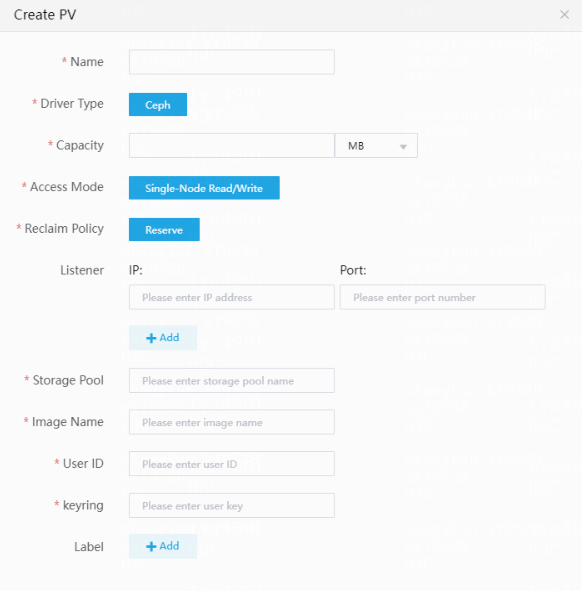
ceph |
Capacity |
Specify the available capacity. |
|
Access Mode |
Select an access mode. Only Single-Node Read/Write is supported, which indicates that a PV can be mounted to a single node in read-write mode. |
|
|
Reclaim Policy |
Only Reserve is supported Select this option to reserve the data in a PV when deleting the PV. |
|
|
Listener/Storage Pool/Image Name/User ID/keyring |
Enter the values according to the configuration in CloudOS deployment. Enter a key value for the keyring parameter. For example, execute the cat /etc/ceph/ceph.client.admin.keyring command to obtain the key value. Enter AQA++oJeqAdBFhAAegoFMusqCYCq1mylc35gBA== for the keyring parameter. |
|
|
Labels |
Optional. Configure labels for the storage volume. |
|
Figure 39 Configuring iSCSI
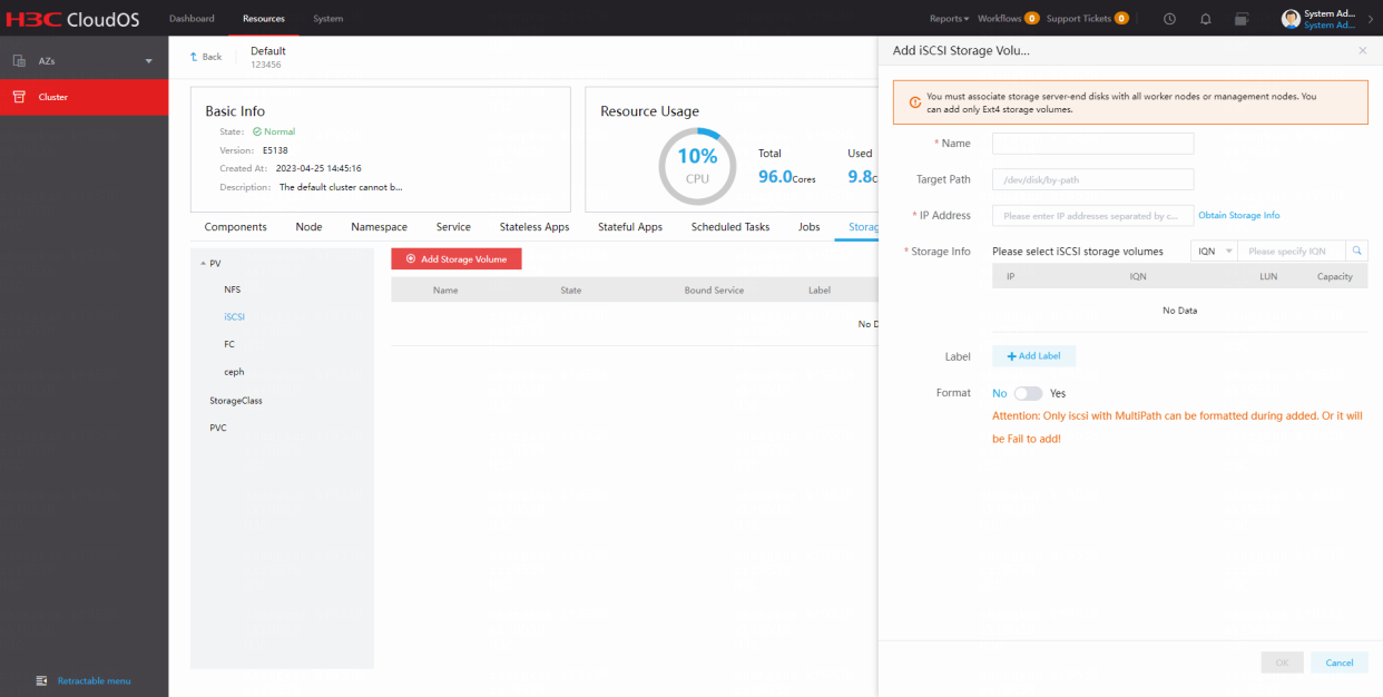
Figure 40 Configuring FC
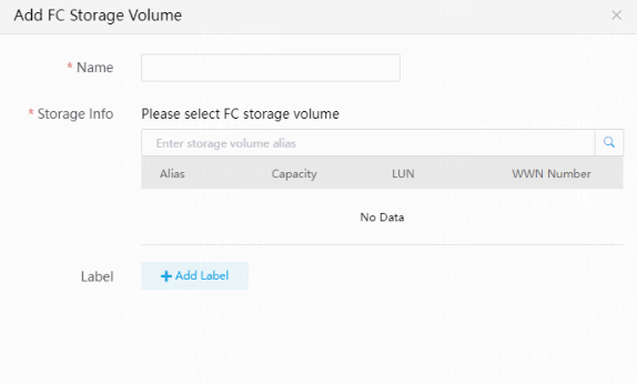
Figure 41 Configuring ceph
4. Click OK.
Uploading installation packages
Upload Harbor installation packages prior to cloud service installation packages.
Upload Nexus installation packages prior to PaaS installation packages.
To upload installation packages by using the SFTP tool, use the complete path on top of the Deployment Guide page. The address for connecting to the server is the IP address on top of the Deployment Guide page. The user name is root and the default password is Passw0rd@_.
To upload installation packages:
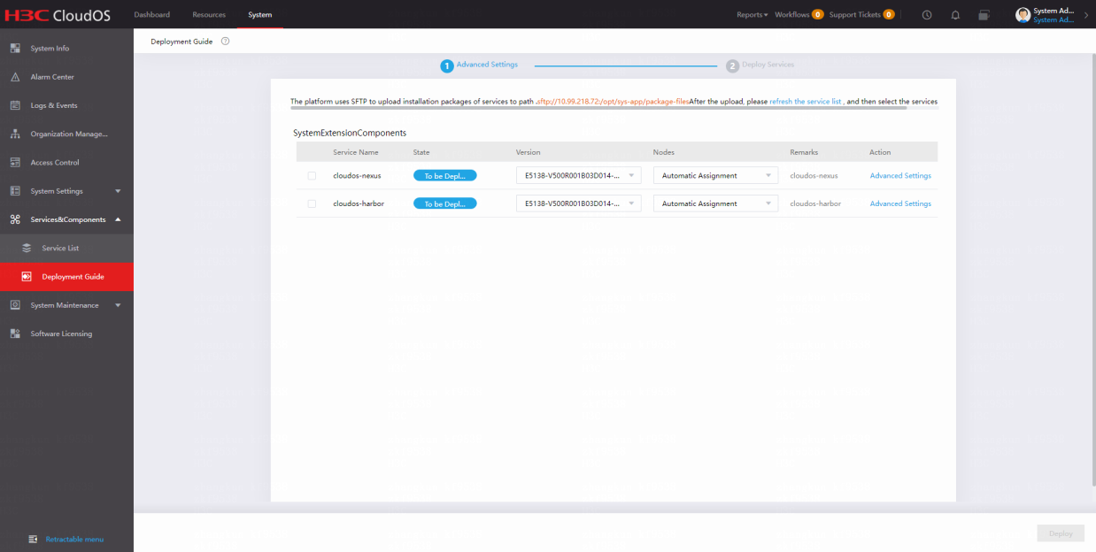
1. On the top navigation bar, click System.
2. From the left navigation pane, select Service&Components > Deployment Guide.
3. Upload the installation package as prompted by using the FTP tool. Refresh the list to view information about the installation package.
Figure 42 Deployment Guide page
Deploying installation packages
Deploy Nexus prior to PaaS to ensure successful deployment of PaaS.
Deploy Harbor prior to cloud services or components to ensure successful deployment of cloud services and components.
This section describes how to deploy cloud services and components. Deploy Harbor first, and then deploy cloud services and components as required. You can deploy one component or cloud service at a time.
To deploy installation packages:
1. On the Deployment Guide page, select the installation packages to be deployed. Select the configured shared storage on the Advanced Settings page. Verify that the versions and nodes where the cloud services and components to be deployed are correct.
Figure 43 Deploying installation packages
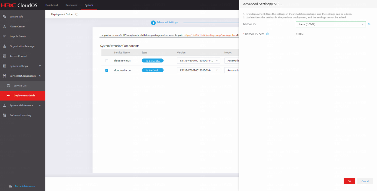
Figure 44 Advanced Settings page
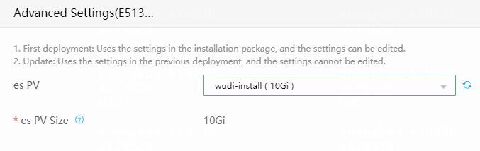
2. Click Deploy, and then click OK.
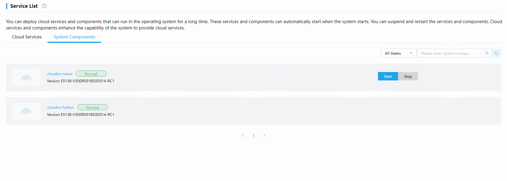
3. Click the Cloud Services tab to verify the deployment progress of services.
A successfully deployed service is enabled by default.
Figure 45 Deployment completed
Appendix
Configuring NIC bonding
You can bond NICs by using the Linux commands. Bond NICs before cluster deployment.
About NIC bonding
NIC bonding (link aggregation) bundles multiple physical Ethernet links into one logical link to increase bandwidth and improve link reliability. You can configure NIC bonding for all networks of the CloudOS cluster, including management, cluster, and storage networks.
Figure 46 Network diagram

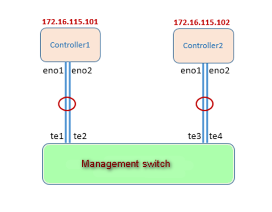
Example
As shown in Figure 47, each controller node has established two physical links to the management network switch through NICs eno1 and eno2. You can bond the two physical links into one logical link.
You can configure NIC bonding mode0 or mode4 for the management, cluster, and storage networks of the CloudOS cluster.
· Mode=0(balance-rr)—Round robin load balancing, which must be configured together with the aggregate enforcer pattern.
· Mode=4(802.3ad)—802.3ad is supported. It must be configured together with the LACP pattern (xmit_hash_policy is required).
Figure 47 Management network NIC bonding
Procedure
Configuring NIC bonding on the controller nodes
1. Use the nmcli connection add type bond ifname bond0 mode 0 command to create a logical NIC with aggregate interface name bond0 and mode 0.
|
|
CAUTION: An aggregate interface name must start with bond. |
2. Bond physical NICs eno1 and eno2 to aggregate interface bond 0 by using the nmcli connection add type bond-slave ifname eno1 master bond0 and nmcli connection add type bond-slave ifname eno2 master bond0 commands, respectively.
Replace eno1 and eno2 with the actual NIC names.
If NIC bonding mode4 is used, you must change mode 0 to mode 4 when creating logical NICs on the server end.
nmcli connection add type bond ifname bond0 mode 4
3. Restart the network by using the service network restart command.
4. Display information about the aggregate interface by using the ip a command to verify that the interface is in up state and has obtained an IP address.
5. Access the /etc/sysconfig/network-scripts path to modify the configuration file ifcfg-bond-bond0 of bond0. Configure a static IP address and a default gateway address for the aggregate interface.
Figure 48 Editing configuration file of bond0

6. Use vi to configure a static IP address and a default gateway address for the aggregate interface. The following is an example of the ifcfg-bond-bond0 configuration file after configuration:
ONDING_OPTS=mode=balance-rr
TYPE=Bond
BONDING_MASTER=yes
PROXY_METHOD=none
BROWSER_ONLY=no
BOOTPROTO=none
DEFROUTE=yes
IPV4_FAILURE_FATAL=no
IPV6INIT=yes
IPV6_AUTOCONF=yes
IPV6_DEFROUTE=yes
IPV6_FAILURE_FATAL=no
IPV6_ADDR_GEN_MODE=stable-privacy
NAME=bond-bond0
UUID=8e876233-a8d9-4fa3-ba87-4161e88e6810
DEVICE=bond0
IPADDR=172.16.150.234
PREFIX=16
GATEWAY=172.16.202.254
ONBOOT=yes
7. Delete the original network configuration files for the bound physical NICs. For example, if the bound physical NICs are eno1 and eno2, delete configuration files ifcfg-eno1 and ifcfg-eno2.
8. Execute the service network restart command to restart the network.
9. Execute the nmcli device status command to display the state of aggregate interface bond0.
The interface is running correctly if it is in connected state.
[root@node-202 ~]# nmcli device status
DEVICE TYPE STATE CONNECTION
bond0 bond connected bond-bond0
Configuring link aggregation on the switch
1. Create a Layer 2 aggregate interface using the static aggregation mode, and configure management VLAN settings based on the network plan.
int Bridge-Aggregation 1
port access vlan xx
2. Add a physical interface to the aggregation group.
interface te1
port access vlan xx
port link-mode bridge
port link-aggregation group 1
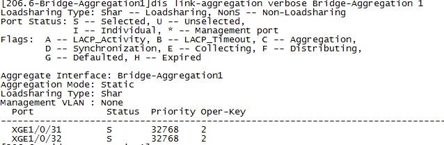
3. Execute the dis link-aggregation verbose Bridge-Aggregation 1 command to display the states of the member ports on the Layer 2 aggregate interface.
Ports in S state are available.
Figure 49 Displaying member state
|
|
NOTE: If NIC bonding mode 4 is used, add the following configuration to the Layer 2 aggregate interface of the switch: |
Verifying the configuration
Verify that controller node 1 and controller node 2 can reach each other.
Installing a USB drive
Creating a bootable USB drive
Preparing the CloudOS installation drive
Before installing CloudOS from a USB drive, prepare the ISO installation drive for CloudOS. The installation drive file name is H3C-CloudOS 5.0-E5XXX.iso, where XXX represents the version number.
Preparing the USB drive
Make sure the USB drive capacity is larger than the CloudOS Plat installation drive capacity (10 GB).
Creating the bootable USB drive
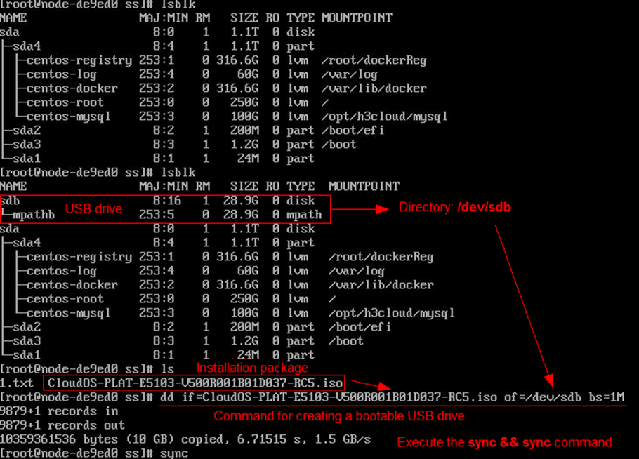
1. Execute the dd if=xxx.iso of=/dev/yyy bs=1M command on Linux to create the bootable USB drive. /dev/yyy represents the drive letter of the USB drive.
2. Execute the sync && sync command.
Figure 50 Creating the bootable USB drive
The following figure is for your reference only.
Installing ISO
Install ISO on a physical server. Only the UEFI boot mode is supported. UEFI is a new BIOS.
To install CloudOS in UEFI boot mode through a USB disk:
1. Set the boot mode of the server to UEFI.
2. Install the USB drive on the server.
3. Enter the server BIOS and select USB drive as the first boot device.
4. Restart the server.
The installation page opens.
Figure 51 Installation page
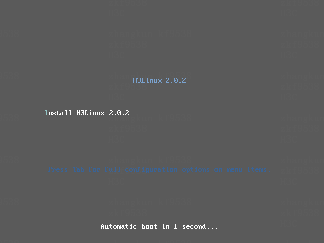
5. Select Install H3Cloud.
Formatting storage volumes
Formatting non-multipath storage volumes
1. Execute the ll /dev/disk/by-path command to obtain the drive letter of the storage volume, for example, sdf.
Figure 52 Obtaining the drive letter of the storage volume
2. Execute the mkfs.ext4 /dev/sdf command.
Formatting multipath storage volumes
1. Execute the ll /dev/disk/by-path command to obtain the drive letter of the storage volume, for example, sdf.
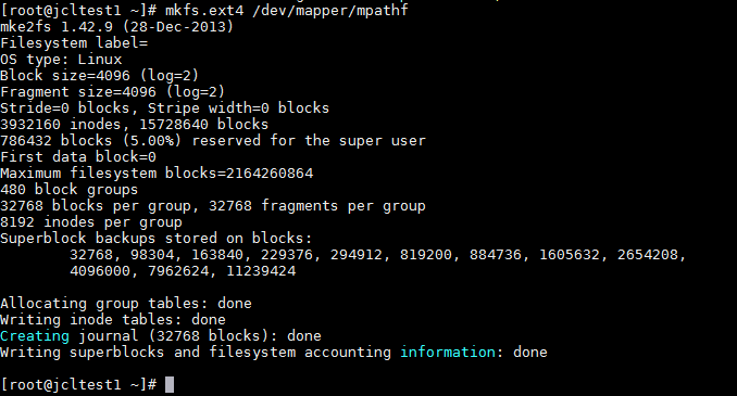
2. Execute the multipath –ll command to obtain the multipath name of the storage volume, for example, mpathf.
Figure 53 Obtaining the relation between the multipath name and storage volume
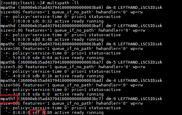
3. Execute the mkfs.ext4 /dev/mapper/mpathf command.
Figure 54 Formatting the storage volume
Configuring edge ports on the switch
You can configure a port on the switch which connects to the server as an edge port in some scenarios.
Configuring a port as an edge port
By default, a switch is enabled with the spanning tree feature. To configure all ports on the switch that connect to the server as edge ports, execute the stp edged-port command.
By default, all ports are non-edge ports.
Command
Use stp edged-port to configure a port as an edge port.
Use undo stp edged-port to restore the default.
Views
Layer 2 Ethernet interface view
Layer 2 aggregate interface view
Layer 2 RPR logical interface view
Predefined user roles
network-admin
mdc-admin
Usage guidelines
A port directly connecting to a user terminal rather than another device or a shared LAN segment can be configured as an edge port. In case the network topology changes, an edge port does not cause a temporary loop. You can enable the port to transit to the forwarding state rapidly by configuring it as an edge port. As a best practice, configure ports that directly connect to user terminals as edge ports.
Typically, configuration BPDUs from other devices cannot reach an edge port, because the edge port does not connect to any other device. When BPDU guard is disabled on a port configured as an edge port, the port acts as a non-edge port if it receives configuration BPDUs.
On a port, the loop guard feature and the edge port setting are mutually exclusive.
If this command is configured in Layer 2 Ethernet interface view, it takes effect only on that interface.
If this command is configured in Layer 2 aggregate interface view, it takes effect only on the aggregate interface.
If this command is configured on a member port in an aggregation group, it takes effect only after the port leaves the aggregation group.
Examples
# Configure GigabitEthernet 1/0/1 as an edge port.
<Sysname> system-view
[Sysname] interface gigabitethernet 1/0/1
[Sysname-GigabitEthernet1/0/1] stp edged-port
Configuring an aggregate interface as an edge aggregate interface
By default, an aggregate interface does not operate as an edge aggregate interface.
Command
Use lacp edge-port to configure an aggregate interface as an edge aggregate interface.
Use undo lacp edge-port to restore the default.
Views
Layer 2 aggregate interface view
Layer 3 aggregate interface view
S-channel bundle interface view
Predefined user roles
network-admin
mdc-admin
Usage guidelines
Use this command on the aggregate interface that connects the device to a server if dynamic link aggregation is configured only on the device. This feature improves link reliability by enabling all member ports of the aggregation group to forward packets.
This command takes effect only on an aggregate interface corresponding to a dynamic aggregation group.
Link-aggregation traffic redirection cannot operate correctly on an edge aggregate interface.
Examples
# Configure Layer 2 aggregate interface Bridge-Aggregation 1 as an edge aggregate interface.
<Sysname> System-view
[Sysname] interface bridge-aggregation 1
[Sysname-Bridge-Aggregation1] lacp edge-port
FAQ
Installation
What should I do when the system prompts "Are you sure you want to erase ALL data on disk XXX? (y/n)"?
To erase all data on the target disk, enter y, and then enter y again when the "Warning! ALL data will be lost! continue? (y/n)" prompt appears. XXX represents the disk ID, sda or vda for example.
CloudOS will format the disk and then you can go to 3 to continue installation. Back up the data before this operation.
Figure 55 Formatting the disk
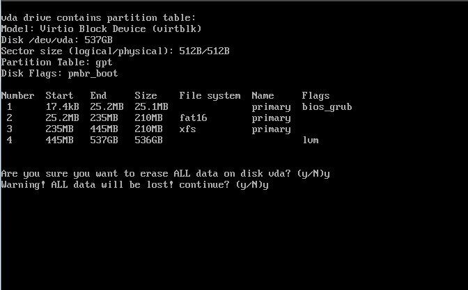
If you do not want to format the disk, enter n. The system will restart.
Figure 56 Refusing to format the disk

What should I do when the system prompts "WARNING, Which of the detected hard drivers do you want to be used as the installation target?”?
· If no data exists on the target disk, input the target disk name, vda for example, and then press Enter. CloudOS will format the disk and then you can go to 3 to continue installation.
Figure 57 No data exists on the target disk
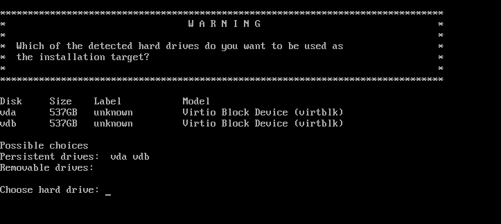
· If data exists on the target disk, input the target disk ID, vda for example, and then press Enter. CloudOS will prompt "Are you sure you want to erase ALL data on disk vda? (y/n)". See "What should I do when the system prompts "Are you sure you want to erase ALL data on disk XXX? (y/n)"?"
As shown in the following figure, vda is the disk that has data, and vdb is the new disk that does not have data.
Figure 58 Data exists on the target disk
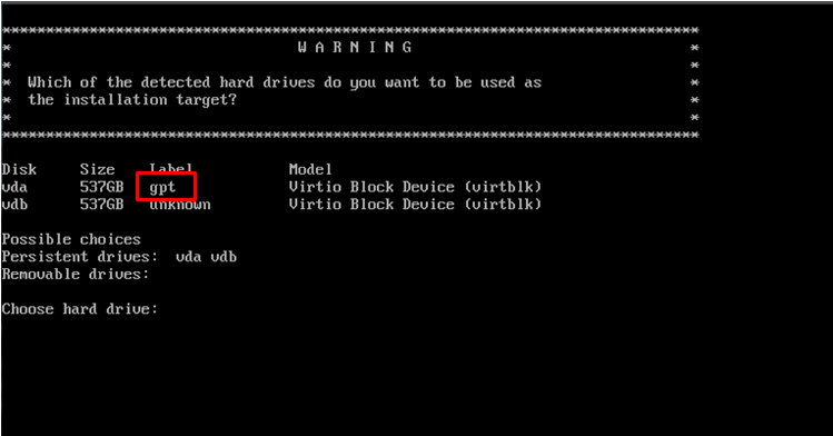
What should I do when the system prompts "ERROR, Your disk is under 500GB in size. Installation cannot continue. Restart installation with a larger disk.”?
Use a disk larger than 500 GB. The minimum size of the disk for installing an OS is 500 GB.
Figure 59 Disk size smaller than 500GB
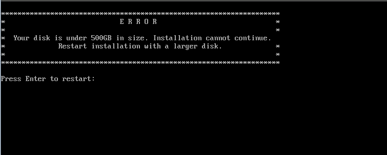
I failed to install CloudOS by mounting the ISO because of unstable console connection and the system prompts "There was an error running the kickstart scprit at line 410.......”. What should I do?
Use the server console to remount the ISO or install CloudOS by using a USB drive.
Deployment
How do I perform a disk IO benchmark test before node deployment
|
|
IMPORTANT: To perform the test, you must install test tool fio. |
1. Access the disk mount points /var/lib/etcd and /${HOSTNAME}.etcd.
2. Create directory test-data.
3. Execute the following command:
fio --rw=write --ioengine=sync --fdatasync=1 --directory=test-data --size=22m --bs=2300 --name=mytest
The following is the test result:
fsync/fdatasync/sync_file_range:
sync (usec): min=534, max=15766, avg=1273.08, stdev=1084.70
sync percentiles (usec):
| 1.00th=[ 553], 5.00th=[ 578], 10.00th=[ 594], 20.00th=[ 627],
| 30.00th=[ 709], 40.00th=[ 750], 50.00th=[ 783], 60.00th=[ 1549],
| 70.00th=[ 1729], 80.00th=[ 1991], 90.00th=[ 2180], 95.00th=[ 2278],
| 99.00th=[ 2376], 99.50th=[ 9634], 99.90th=[15795], 99.95th=[15795],
| 99.99th=[15795]
99.00th in the fdatasync metric means that 99% of the cache data has been written into the disk within the time range. The time unit of the metric is microseconds.
The test result is 2.376 ms, which is shorter than the recommended value of etcd (10 ms). Therefore, the disk can provide high performance. As a best practice, do not use the disk if the test result exceeds 50 ms.
What should I do if I select a wrong etcd node during node deployment
If you select wrong etcd disks in "Deploying a node," perform the following tasks on all controller nodes:
1. Log in to the back end of each controller node and execute the df -h | grep etcd command.
Two etcd disks are displayed, for example, /dev/sdb and /dev/sdc.
[root@d030sp01node1 ~]# df -h |grep etcd
/dev/sdb1 100G 45M 99G 1% /d030sp01node1.etcd
/dev/sdc1 100G 45M 99G 1% /var/lib/etcd
2. Execute the umount /dev/sdb and umount /dev/sdc commands.
Replace /dev/sdb and /dev/sdc with the actual disk names.
[root@d030sp01node1 ~]# umount /dev/sdb1
[root@d030sp01node1 ~]# umount /dev/sdc1
3. Open file /etc/fstab and delete the two etcd lines.
4. Save and exit the file.
|
|
CAUTION: Perform the above tasks before cluster deployment. After deploying the cluster, migrate etcd data. Contact technical engineers for help. |
What should I do if I fail to deploy CloudOS because SELinux is disabled on a host?
Re-create the bootable USB drive if you misoperate or the USB is faulty during creation. For more information, see "Creating a bootable USB drive."
