- Table of Contents
- Related Documents
-
| Title | Size | Download |
|---|---|---|
| 01-Text | 1.24 MB |
Converged gateway network interfaces
VM networking for communication with external devices
Establishing Layer 2 connectivity between a VM and an external device through a MacVTap NIC
Establishing Layer 2 connectivity between a VM and an external device through an SR-IOV VF
Establishing Layer 3 connectivity between a VM and an external device through a MacVTap NIC
Establishing Layer 3 connectivity between a VM and an external device through an SR-IOV VF
Deployment restrictions and guidelines
Setting up the deployment environment
Connecting the management host and the converged gateway
Configuring network settings for the management host
Examining the file system format
Assigning IP addresses to the SR-IOV physical NICs
Configuring a virtual Ethernet interface
Selecting a VM deployment method
Preparing files for automatic deployment
About files for automatic deployment
Transfering files for automatic VM deployment
Automatically deploying a VM from a USB flash drive
Automatically deploying a VM from the CLI
Configuring VM network settings
Manual VM deployment procedure
Importing a guest OS image file
Attaching a MacVTap NIC to a VM
Attaching an SR-IOV VF NIC to a VM
Installing the guest OS in the VM
Configuring VM network settings
Introduction
This document guides you to deploy virtual machines (VMs) on the following AI-powered ICT converged gateways:
· SR6602-I.
· SR6602-IE.
Supported VM operations
The converged gateways support the following VM operations:
· Creating, managing, or maintaining VM resources from the CLI.
· From the Web GUI of VMs, installing the VM operating systems (guest OSs), configuring VM network settings, and deploying apps.
· Configuring the VMs to provide services.
Supported vNICs
The gateway-hosted VMs communicate with the converged gateway and connect to the network through vNICs. vNICs include MacVTap NICs and single-root I/O virtualization (SR-IOV) virtual functions (VFs).
· A MacVTap NIC is a virtual interface created by using the Linux MACVLAN kernel module.
A MacVTap NIC is bridged to an SR-IOV physical NIC through the Linux Bridge kernel module.
A MacVTap NIC belongs to VLAN 1 by default and cannot be assigned to any other VLANs.
A MacVTap NIC is slower than an SR-IOV VFs.
When you use MacVTap NICs, you do not need to install a driver.
· An SR-IOV VF is virtualized from an SR-IOV physical NIC.
By default, an SR-IOV VF does not belong to any VLAN. You must assign the SR-IOV VF to a VLAN.
An SR-IOV VF NIC forwards traffic at higher speeds than MacVTap NICs. You can assign SR-IOV VF NICs to VLANs as needed.
To use SR-IOV VFs, you must install a driver.
|
|
NOTE: You can attach a MacVTap, an SR-IOV VF, or both types of NICs to a VM. As a best practice to ensure forwarding performance, use SR-IOV VFs. If a VM does not have an SR-IOV VF driver, you must use a MacVTap NIC to download the driver before you can attach an SR-IOV VF to the VM. |
For more information about attaching a vNIC to a VM, see "Attaching vNICs to a VM."
Converged gateway network interfaces
The converged gateway can operate in CT mode or ICT mode. By default, it operates in CT mode. To run VMs on the converged gateway, the converged gateway must operate in ICT mode. For more information about enabling ICT mode, see "Enabling VM capability."
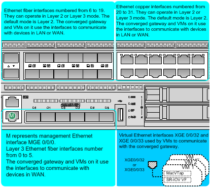
In ICT mode, the converged gateway has 32 fixed physical Ethernet interfaces and 2 virtual Ethernet interfaces.
· Ten-GigabitEthernet 0/0/0 through Ten-GigabitEthernet 0/0/19 are 10GBase-R SFP+ Ethernet fiber interfaces.
· GigabitEthernet 0/0/20 through GigabitEthernet 0/0/31 are 10/100/1000Base-T Ethernet copper interfaces.
· Ten-GigabitEthernet 0/0/32 and Ten-GigabitEthernet 0/0/33 are virtual Ethernet interfaces. The interfaces are connected to the two built-in SR-IOV physical NICs on the converged gateway. VMs use the virtual Ethernet interfaces and switching chips on the converged gateway to exchange data with the converged gateway for WAN and LAN communication.
Figure 1 shows the interfaces on the converged gateway.
Figure 1 Converged gateway interface network diagram
VM networking for communication with external devices
A VM can communicate with an external device in bridged mode at Layer 2 or in routed mode at Layer 3 depending on your networking method.
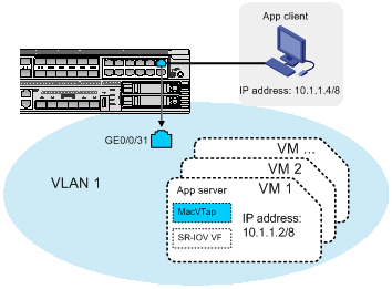
Establishing Layer 2 connectivity between a VM and an external device through a MacVTap NIC
To enable a VM to communicate with an external device at Layer 2 in VLAN 1 through a MacVTap NIC:
1. Configure IP addresses for the host and the MacVTap NIC attached to the VM. Make sure the IP addresses belong to the same subnet.
2. Connect the external device to a Layer 2 Ethernet interface (for example, GE 0/0/31) on the converged gateway.
3. Add this interface to VLAN 1.
4. Assign the MacVTap NIC an IP address in the same subnet as the external device.
Figure 2 Network setup example for Layer 2 connectivity through a MacVTap NIC
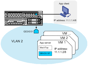
Establishing Layer 2 connectivity between a VM and an external device through an SR-IOV VF
To enable a VM to communicate with an external device at Layer 2 through an SR-IOV VF:
1. Connect the external device to a Layer 2 Ethernet interface (for example, GE 0/0/31) on the converged gateway.
2. Assign the Layer 2 Ethernet interface to the same VLAN as the SR-IOV VF for the VM.
3. Assign the SR-IOV VF an IP address in the same subnet as the external device.
Figure 3 Network setup example for Layer 2 connectivity through through an SR-IOV VF
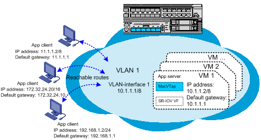
Establishing Layer 3 connectivity between a VM and an external device through a MacVTap NIC
To enable a VM to communicate with an external device on different subnets through a MacVTap NIC, establish Layer 3 connectivity between them, as follows:
1. Connect the external device to a Layer 2 or Layer 3 Ethernet interface on the converged gateway.
2. If the external device is connected to a Layer 2 interface, assign that interface to a VLAN, create the VLAN interface, and assign an IP address to the VLAN interface. If the external device is connected to a Layer 3 Ethernet interface, assign an IP address to the Layer 3 Ethernet interface.
3. Set the default gateway for the external device to the IP address of the VLAN interface or the Layer 3 Ethernet interface. Assign the external device an IP address on the same subnet as its gateway.
4. Create VLAN interface 1 and assign an IP address to the VLAN interface.
5. Set the default gateway for the MacVTap NIC to the IP address of VLAN interface 1. Assign the NIC an IP address on the same subnet as VLAN interface 1.
Figure 4 Network setup example for Layer 3 connectivity through a MacVTap NIC
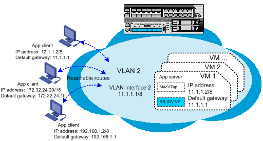
Establishing Layer 3 connectivity between a VM and an external device through an SR-IOV VF
To enable a VM to communicate with an external device on different subnets through an SR-IOV VF, establish Layer 3 connectivity between them, as follows:
1. Connect the external device to a Layer 2 or Layer 3 Ethernet interface on the converged gateway.
2. If the external device is connected to a Layer 2 interface, assign that interface to a VLAN, create the VLAN interface, and assign an IP address to the VLAN interface. If the external device is connected to a Layer 3 Ethernet interface, assign an IP address to the Layer 3 Ethernet interface.
3. Set the default gateway for the external device to the IP address of the VLAN interface or the Layer 3 Ethernet interface. Assign the external device an IP address on the same subnet as its gateway.
4. Create a VLAN and VLAN interface for the SR-IOV VF and assign an IP address to the VLAN interface.
5. Assign the SR-IOV VF to the VLAN created for it, set the default gateway for the SR-IOV VF to the IP address of the VLAN interface. Assign the SR-IOV VF an IP address on the same subnet as that VLAN interface.
Figure 5 Network setup example for Layer 3 connectivity through an SR-IOV VF
VM deployment methods
The ICT converged gateways support the following VM deployment methods:
· Automatic VM deployment.
· Manual VM deployment.
Automatic VM deployment
Automatic VM deployment enables you to bulk-deploy VMs by using a .pkg or .xml VM file.
A .pkg or .xml file contains all parameters that make up a VM. All VMs created from a .pkg or .xml file have the same parameter settings as the source VM, including their CPU and memory settings.
Depending on the storage medium used to store a .pkg VM file, the following automatic deployment methods are available:
· CLI-based automatic VM deployment—If you store the .pkg file on a disk of the converged gateway, use this method to deploy the VM from the CLI of the converged gateway.
· USB-based automatic VM deployment—If you store the .pkg file on a USB flash drive, use this method. To install the VM, you only need to reboot the converged gateway after you insert the USB flash drive.
To deploy a VM based on an .xml VM file, you must store the .xml file and the VM disk file on a disk of the converged gateway. In this situation, you can only deploy the VM from the CLI.
After a VM is deployed, you can tune its settings as needed.
For more information about automatic VM deployment, see "Automatically deploying a VM."
Manual VM deployment
Manual VM deployment enables you to create and set up VMs from the CLI of the converged gateway.
Manual VM deployment is more complicated than automatic VM deployment. Typically, use manual deployment only if you do not have a .pkg or .xml VM file or cannot export one from an existing VM.
For more information about manual VM deployment, see "Manually deploying a VM."
VM GUI login method
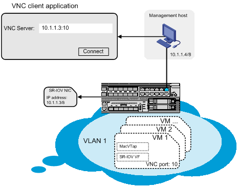
Use a VNC client application installed on the management host to log in to the GUI of a VM by connecting to the VNC server on the converged gateway.
As shown in Figure 6:
· Connect the host to a Layer 2 Ethernet interface on the converged gateway.
· Assign the management host an IP address on the same subnet as the IP address of the SR-IOV physical NIC to which the VM is attached.
In the VNC client, enter the server address in VNC server IP address:VNC port number format.
· VNC server IP address—The IP address of the SR-IOV physical NIC on the converged gateway.
· VNC port number—The VNC port number configured when the VM is deployed.
For information about configuring an IP address for an SR-IOV physical NIC, see "Assigning IP addresses to the SR-IOV physical NICs."
Deployment restrictions and guidelines
The default memory (8 GB) and built-in storage (4 GB) of the SR6602-I gateway are limited. To ensure VM performance, use the following guidelines when you deploy VMs on the SR6602-I gateway:
· Expand the memory.
A memory size of 8 GB is only sufficient for running Comware.
· Install a minimum of one expansion disk to deploy VMs.
The SR6602-IE gateway comes with 32 GB memory and 64 GB built-in flash storage by default. You can deploy VMs in built-in flash memory or on an expansion disk and make a memory expansion decision as needed, depending on your network performance requirements.
The expansion disks can be SATA or M.2 drives.
Prerequisites
This document uses an SR6602-IE converged gateway to describe the VM deployment procedures.
This document does not provide detailed information about the commands used in the deployment procedures. For more information about those commands, see H3C SR6602-I[IE] AI-Powered ICT Converged Gateways Command References.
Preparing for VM deployment
Before you deploy VMs, perform the following tasks:
1. Setting up the deployment environment
2. Connecting the management host and the converged gateway
3. Configuring network settings for the management host
4. Configuring the converged gateway:
¡ Examining the file system format
¡ Assigning IP addresses to the SR-IOV physical NICs
¡ Configuring a virtual Ethernet interface
5. Selecting a VM deployment method
Setting up the deployment environment
· Prepare a management host, a network cable, and a serial cable.
· To access the CLI of the converged gateway through the console port, install a terminal emulation program on the management host. You can create VMs and configure VM parameters at the CLI.
· To access the GUI of the VM, install a VNC client on the management host. On the GUI, you can install guest OSs and applications in the VM, set up the VM network, and manage services.
· To transfer VM deployment files to the converged gateway, set up an FTP server on the management host.
Connecting the management host and the converged gateway
· Use a serial cable to connect the management host to the console port of the converged gateway.
· Use a network cable to connect the management host to a Layer 2 Ethernet interface (for example, GE 0/0/31) of the converged gateway. The host can communicate with the converged gateway and the physical NICs of the converged gateway in VLAN 1.
Figure 7 Network scheme
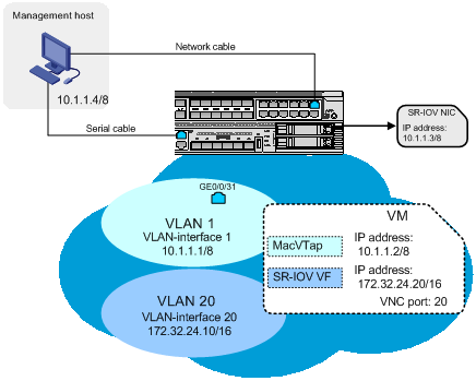
Table 1 Component description
|
Component name |
Description |
|
Management host |
The host from which you access the CLI of the converged gateway and log in to the GUI of a VM. |
|
GE 0/0/31 |
Layer 2 Ethernet interface that provides Layer 2 connectivity between the converged gateway and the management host. |
|
SR-IOV NIC |
SR-IOV physical NIC that provides network services for VM GUI login. |
|
VM |
VM. |
|
MacVTap |
The vNIC used by the VM to establish Layer 2 or Layer 3 connectivity, especially for initial access to the network. |
|
SR-IOV VF |
The vNIC used by the VM to establish Layer 2 or Layer 3 connectivity for access to the network. |
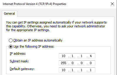
Configuring network settings for the management host
This task uses a Windows host to describe the network setup procedure.
1. On the management host, open the Network and Sharing Center and select Local Area Connection.
2. In the dialog box that opens, click Properties.
3. In the dialog box that opens, select Internet Protocol Version 4 (TCP/IPv4) and click Properties.
4. In the dialog box that opens, configure the IP address settings.
In this example, the IP address is 10.1.1.4/8.
Figure 8 Configuring network settings for the management host
Examining the file system format
About this task
Perform this task to verify that the file system format of the partition for VM deployment is EXT4.
This document uses the built-in storage (sda) of the SR6602-IE converged gateway to describe the VM deployment procedure. On the SR6602-I converged gateway, use an expansion disk for VM deployment.
The built-in storage (sda) of the converged gateway has the following partitions:
· Partition sda0 stores system files. You cannot deploy VMs on this partition.
· Partition sda1 stores configuration files. You deploy VMs on this partition. In this deployment guide, VMs are deployed on the sda1 partition.
Restrictions and guidelines
Changing the file system format of a disk will delete all data from that disk. Before you use the format command to change the file system format, back up data for the disk.
Procedure
1. Verify that the file system format of the disk partition for VM deployment is EXT4. In this example, verify that the file system format of partition sda1 is EXT4.
<Sysname> dir sda1:/
Directory of sda1: (EXT4)
The output shows that the file system format of partition sda1 is EXT4.
2. If the format of the file system is not EXT4, change its format to EXT4.
<Sysname> format sda1: ext4
All data on sda1: will be lost, continue? [Y/N]:Y
...
Enabling VM capability
About this task
By default, VM capability (ICT mode) is disabled. Before VM deployment, use the ict mode enable command to enable VM capability on the converged gateway.
When you enable VM capability, you can set the number of CPU cores and the amount of memory allocated to the VM plane.
If you do not set the parameters, the following default settings apply:
· The number of CPU cores allocated to the VM plane is the total number of CPU cores on the converged gateway minus 2.
· The amount of memory allocated to the VM plane is the total amount of memory on the converged gateway minus 8 GB.
In this example, six CPU cores and 12 GB of memory are allocated to the VM plane.
Procedure
# Enable VM capability and allocate six CPU cores and 12 GB of memory to the VM plane.
<Sysname> system-view
[Sysname] ict mode enable vcpu-pool 6 vmem-pool 12
[Sysname] quit
# Reboot the converged gateway to have the configuration take effect.
<Sysname> reboot
Assigning IP addresses to the SR-IOV physical NICs
About this task
By default, no IP addresses are assigned to the built-in SR-IOV physical NICs on the converged gateway.
To access the GUI of a VM from a remote VNC client, you must first assign an IP address to the SR-IOV physical NIC to which the VM is attached.
Procedure
1. Identify the names of the SR-IOV physical NICs on the converged gateway.
<Sysname> display sriov-vf-pciaddr
enp182s0f2:
vf 00 pci-addr 0000:b6:0a.0
...
enp182s0f3:
vf 00 pci-addr 0000:b6:0e.0
...
2. Assign an IP address and mask to the NIC to which the VM is attached. In this example, assign IP address 10.1.1.3 and mask 255.0.0.0 to SR-IOV physical NIC enp182s0f2.
<Sysname> system-view
[Sysname] vmm
[Sysname-vmm] ifconfig enp182s0f2 10.1.1.3 netmask 255.0.0.0
3. Verify that the IP address has been assigned successfully.
[Sysname-vmm] ifconfig enp182s0f2
enp182s0f2: flags=4163<UP,BROADCAST,RUNNING,MULTICAST> mtu 1500
inet 10.1.1.3 netmask 255.0.0.0 broadcast 10.1.1.255
inet6 fe80::200:ff:fe00:8062 prefixlen 64 scopeid 0x20<link>
ether 00:00:00:00:80:62 txqueuelen 1000 (Ethernet)
RX packets 0 bytes 0 (0.0 B)
RX errors 0 dropped 0 overruns 0 frame 0
TX packets 8 bytes 648 (648.0 B)
TX errors 0 dropped 0 overruns 0 carrier 0 collisions 0
[Sysname-vmm] quit
Configuring a virtual Ethernet interface
About this task
The SR-IOV VFs of VMs are connected to the converged gateway through virtual Ethernet interfaces Ten-GigabitEthernet 0/0/32 and Ten-GigabitEthernet 0/0/33.
By default, the virtual Ethernet interfaces belong to VLAN 1 and their link type is access. To make sure the VMs can access the network in a multi-VLAN context:
· Change the link type of the interfaces to trunk.
· Configure the interfaces to allow traffic from all VLANs to pass through.
This document uses virtual Ethernet interface Ten-GigabitEthernet 0/0/32 as an example to describe the configuration procedure.
Restrictions and guidelines
The converged gateway supports only Layer 2 access to the GUI of a VM. To ensure a successful access, do not change the virtual Ethernet interfaces from the default bridged (Layer 2) mode to routed (Layer 3) mode.
Procedure
# Set the link type of Ten-GigabitEthernet 0/0/32 to trunk and configure the interface to permit traffic from all VLANs to pass through.
[Sysname] interface ten-gigabitethernet0/0/32
[Sysname-Ten-GigabitEthernet0/0/32] port link-type trunk
[Sysname-Ten-GigabitEthernet0/0/32] port trunk permit vlan all
[Sysname-Ten-GigabitEthernet0/0/32] quit
[Sysname] quit
Selecting a VM deployment method
1. Select manual deployment or automatic deployment, as shown in Figure 9.
¡ To deploy a VM from a .pkg or xml. VM file, select automatic deployment.
¡ To deploy a VM from scratch, perform a manual deployment. For more information about the deploy procedure, see "Manually deploying a VM."
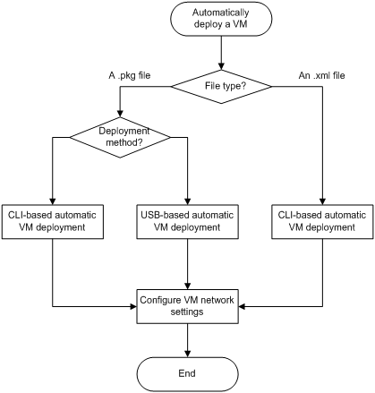
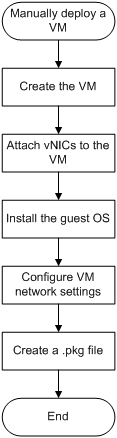
2. If you select automatic deployment, use the workflow in Figure 10 to select a deployment procedure.
Use the following guidelines when you select an automatic deployment procedure:
¡ Select USB-based automatic deployment for the ease of deployment if the following conditions are all met:
- You have local access to both the source and destination converged gateways.
- A USB flash drive is available.
¡ Select CLI-based automatic deployment in one of the following situations:
- You remotely manage the source and destination converged gateways.
- You need to deploy the VM from an .xml file.
- A USB flash drive is not available.
- You do not need to reboot the destination converged gateway.
For information about the automatic deployment procedures, see "Automatically deploying a VM."
|
|
NOTE: In this document, the source converged gateway is the device on which a .pkg or .xml VM file is created. The destination converged gateway is the device on which the .pkg or .xml VM file is installed. |
Figure 9 Selecting a VM deployment method
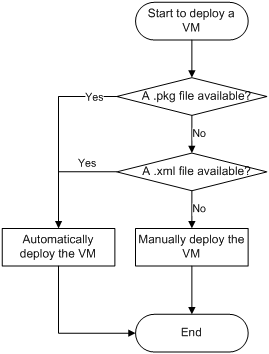
Figure 10 Automatic VM deployment workflow
Automatically deploying a VM
To automatically deploy a VM:
1. Preparing files for automatic deployment
Skip this step if you are deploying the VM from an .xml file.
b. Transfering files for automatic VM deployment
2. Deploying the VM
¡ Automatically deploying a VM from a USB flash drive
To deploy the VM from a USB flash drive, you must use a .pkg file.
¡ Automatically deploying a VM from the CLI
3. Configuring VM network settings
Preparing files for automatic deployment
About files for automatic deployment
To perform a USB-based automatic deployment, you must create a .pkg file from the source VM and copy the file to a USB flash drive.
To perform a CLI-based automatic deployment, you must copy the .xml file of the source VM and its associated .qcow disk file to a USB flash drive or transfer the files through FTP.
You do not need to create the .xml file or its associated disk file.
|
|
NOTE: The .xml file is stored in the drive:/etc/libvirt/qemu/ directory. For example, if the VM is deployed on sda1, the .xml file is stored in the sda1:/etc/libvirt/qemu/ directory. |
Creating a .pkg file
About this task
Perform this task to export an existing VM as a .pkg file.
Procedure
1. Verify that the source VM is operating correctly and shut it down:
a. Log in to the source VM from the VNC client to verify that the VM is operating correctly. In this example, VM centos7 is the source VM.
b. Shut down the VM.
<Sysname> system-view
[Sysname] vmm
[Sysname-vmm] virsh shutdown centos7
c. Verify that the VM has shut down.
[Sysname-vmm] virsh list --all
Id Name State
----------------------
1 centos7 shutoff
2. Create a .pkg VM file out of the VM.
[Sysname-vmm] export centos7 /mnt/sda1:/centos7.pkg
Ensure the destination has enough space?(if not, the pkg file may be unavailable.)[Y/N]:Y
Exporting domain centos7...
Transfering files for automatic VM deployment
About this task
Use a USB flash drive or use FTP to transfer files for VM deployment.
If you use FTP for file transfer, use the source converged gateway as the FTP server and the destination converged gateway as the FTP client.
Transfering the VM files to a USB flash drive
1. Verify that the file system format of the USB flash drive is EXT4:
# Display the file system format of the USB flash drive.
<Sysname> dir usba0:/
Directory of usba0: (EXT4)
The output shows that the file system format of the USB flash drive is EXT4.
# (Optional.) Set the file system format of the USB flash drive to EXT4.
<Sysname> format usba0: ext4
All data on usba0: will be lost, continue? [Y/N]:Y
2. Create file folder VmImages in the root directory of the USB flash drive.
<Sysname> mkdir usba0:/VmImages
Creating directory usba0:/VmImages... Done.
3. Copy the VM files to the usba0:/VmImages/ directory.
In this example, copy file centos7.pkg in the sda1:/ directory to the usba0:/VmImages/ directory of the USB flash drive.
<Sysname> copy sda1:/centos7.pkg usba0:/VmImages/
|
|
NOTE: The .xml file is stored in the drive:/etc/libvirt/qemu/ directory. For example, if the VM is deployed on sda1, the .xml file is stored in the sda1:/etc/libvirt/qemu/ directory. |
Using FTP to transfer the VM files
1. Configure the source converged gateway:
# Add a user named admin. Set the user password to admin123, assign role network-admin to the user, and allow the user to access the root directory of disk sda1 and use the FTP service.
<Sysname> system-view
[Sysname] local-user admin class manage
[Sysname-luser-manage-abc] password simple admin123
[Sysname-luser-manage-abc] authorization-attribute user-role network-admin work-directory sda1:/
[Sysname-luser-manage-abc] service-type ftp
[Sysname-luser-manage-abc] quit
# Enable the FTP server on the source converged gateway.
[Sysname] ftp server enable
[Sysname] quit
2. Configure the destination converged gateway:
# Change the current directory to the root directory of disk sda1 on the destination converged gateway and connect to the FTP server. In this example, the IP address of the FTP server is 10.1.1.5.
<Sysname> cd sda1:/
<Sysname> ftp 10.1.1.5
220 FTP service ready.
# Enter the FTP username and password for accessing the FTP server. The username and password must be the same as those configured on the FTP server.
User (10.1.1.5:(none)): admin
331 Password required for abc.
Password:
230 User logged in.
# Set the transfer mode to binary to transfer the .pkg file to the root directory of disk sda1 on the destination converged gateway. In this example, a .pkg VM file is used.
ftp> binary
200 TYPE is now 8-bit binary
ftp> get centos7.pkg
...
# Verify that the file has been transferred to the destination converged gateway successfully. The file transfer is finished if the following message appears:
226 Closing data connection; File transfer successful.
4521459712 bytes received in 385.518 seconds (11.18 Mbytes/s)
# Terminate the FTP connection.
ftp> quit
Automatically deploying a VM from a USB flash drive
About this task
You must use a .pkg file for automatic VM deployment from a USB flash drive.
Prerequisites
Make sure you have completed the following tasks:
2. Transfering the VM files to a USB flash drive
Procedure
1. Insert the USB flash drive into the destination converged gateway.
2. Start up or reboot the destination converged gateway.
<Sysname> reboot
The converged gateway automatically deploys the VM.
|
|
NOTE: The amount of time used to deploy a VM depends on the size of the .pkg VM file. |
3. Configure VM network settings.
For more information about the procedure, see "Configuring VM network settings."
Automatically deploying a VM from the CLI
About this task
To deploy a VM from the CLI, you can use a .pkg or .xml VM file. If a .xml VM file is used, you must also use its associated .qcow disk file.
Usage guidelines
For the deployed VM to operate, make sure the destination directory for the .qcow VM disk file is the same as the disk directory in the .xml file.
Prerequisites
Make sure you have prepared and transferred the VM files for deployment. For more information about the procedure, see "Preparing files for automatic deployment."
Procedure
1. If the VM files are on a USB flash drive:
a. Insert the USB flash drive to the destination converged gateway.
b. Copy the .pkg VM file or copy the .xml VM file and its associated .qcow VM disk file to the destination converged gateway.
In this example, copy file centos7.pkg in the usba0:/ directory to the sda1:/ directory.
<Sysname> copy usba0:/centos7.pkg sda1:/
Skip this step if you have transferred the VM files to the destination converged gateway.
2. Enter VMM view and create the VM.
¡ Install the .pkg file to create VM centos7.
<Sysname> system-view
[Sysname] vmm
[Sysname-vmm] import /mnt/sda1:/centos7.pkg
Import domain package centos7.pkg...
VM deployment completes when the VMM view appears again.
[Sysname-vmm]
¡ Install the .xml file to create VM centos7.
<Sysname> system-view
[Sysname] vmm
[Sysname-vmm] virsh define /mnt/sda1:/centos7.xml
Domain centos7 defined from /mnt/sda1:/centos7.xml
3. Configure VM network settings.
For more information about the procedure, see "Configuring VM network settings."
Configuring VM network settings
To configure the network settings of a VM:
|
|
NOTE: The following information uses a CentOS to describe the network setup procedure. The GUI differs depending on the guest OS. |
Logging in to the VM GUI
1. Enter VMM view and start the VM. For example, start VM centos7.
[Sysname-vmm] virsh start centos7
Domain centos7 started
2. Verify that VM centos7 is running.
[Sysname-vmm] virsh list --all
Id Name State
----------------------
1 centos7 runnig
3. Display the VNC port number of VM centos7.
[Sysname-vmm] virsh vncdisplay centos7
:20
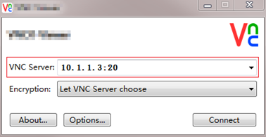
4. On the management host, open the VNC client, and then enter the VNC server address for the VM in the format of VNC server IP address:VNC port number, as shown in Figure 11.
Figure 11 VNC app login interface

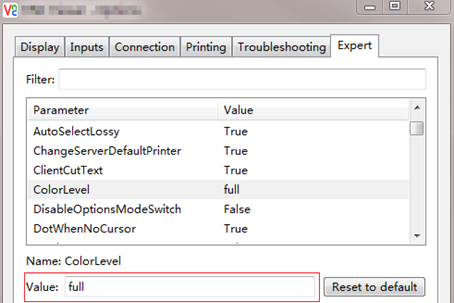
5. (Optional.) If the VNC client closes incorrectly, re-open it and set the VNC configuration color level to full, as shown in Figure 12.
Figure 12 Modifying the color level

Configuring a MacVTap NIC
About this task
For the VM to communicate with external devices through the MacVTap NIC attached to it, you must assign an IP address to that MacVTap NIC.
This task is required for you to download an SR-IOV VF driver.
Procedure
1. On the converged gateway, identify the MAC address of the MacVTap NIC to which the VM is attached. In this example, VM centos7 is used.
<Sysname> system-view
[Sysname] vmm
[Sysname-vmm] virsh domiflist centos7
Interface Type Source Model MAC
-----------------------------------------------------------
macvtap0 direct enp182s0f2 e1000 80:48:80:62:10:3a
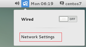
2. On the desktop of the guest OS (CentOS 7 in this example), click Network Settings, as shown in Figure 13.
Figure 13 Configuring network settings
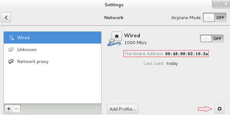
3. Find the MacVTap NIC with the MAC address specified in "Attaching a MacVTap NIC to a VM," and click the gear icon in the lower right corner to add NIC settings, as shown in Figure 14. In this example, the MAC address of the MacVTap NIC is 80:48:80:62:10:3a.
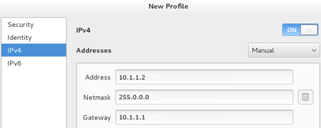
4. Select IPv4, configure the IP address and add the gateway, as shown in Figure 15. The gateway address is the IP address of VLAN-interface 1. The IP address of the MacVTap NIC must be on the same subnet as the IP addresses of the management host and the gateway VLAN interface. In this example, the IP address of the MacVTap NIC is 10.1.1.2/8.
Figure 15 Configuring IP address settings
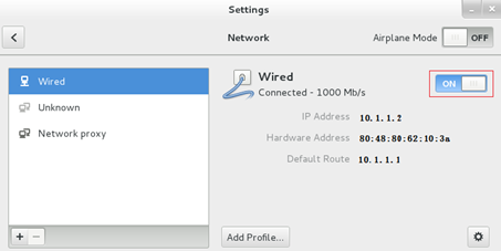
5. Disable and then re-enable the MacVTap NIC for the configuration to take effect, as shown in Figure 16.
Figure 16 Disabling and re-enabling the NIC
6. Use the ping command to verify that the VM can communicate with the management host and converged gateway. (Details not shown.)
Configuring an SR-IOV VF
About this task
For the SR-IOV VFs on a VM to operate correctly, you must install the SR-IOV VF driver for the guest OS.
The SR-IOV VF driver for a Linux system is Intel® Network Adapter Linux* Virtual Function Driver for Intel® Ethernet Controller 700 and E810 Series.
The SR-IOV VF driver for Windows 2012 is Intel® Network Adapter Driver for Windows Server 2012*.
Procedure
1. Downloading an SR-IOV VF driver
Skip this step if the VM file already has an SR-IOV VF driver.
2. Installing the SR-IOV VF driver
Skip this step if the VM file already has an SR-IOV VF driver.
3. Configuring IP address settings for the SR-IOV VF
Downloading an SR-IOV VF driver
1. Download an SR-IOV VF driver to a directory on the FTP server. In this example, FTP server is on the management host, and the driver file is ixgbevf-5.3.4.tar.gz.
¡ To download an SR-IOV VF driver for a Linux system, access https://downloadcenter.intel.com/zh-cn/download/24693
¡ To download an SR-IOV VF driver for Windows 2012, access https://downloadcenter.intel.com/zh-cn/download/21694
|
|
NOTE: If the download links are inaccessible, access the Intel download center to download the SR-IOV driver. |
2. Make sure you have configured the MacVTap NIC of the VM to provide network services.
3. Transfer the driver from the FTP server to the converged gateway. For more information about configuring and using FTP to transfer files, see "Importing a guest OS image file."
Installing the SR-IOV VF driver
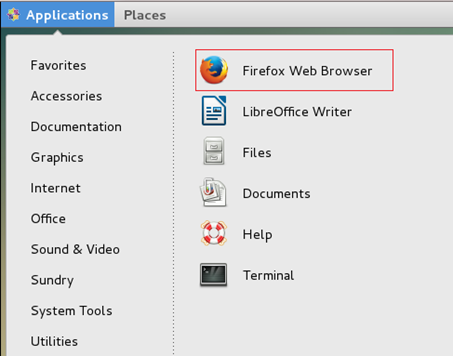
1. Open the Firefox web browser that came with the CentOS system.
Figure 17 Opening the Firefox web browser
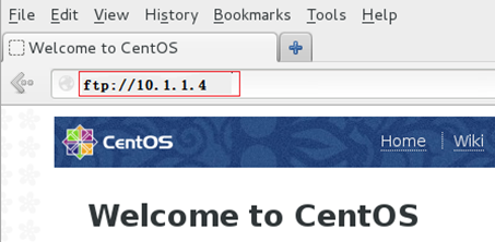
2. Enter the FTP server address to access the FTP server, find file ixgbevf-5.3.4.tar.gz, and save the file on the VM.
Figure 18 Accessing the FTP server
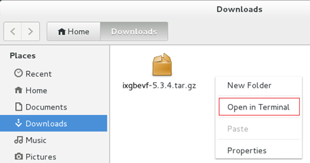
3. Open the directory where the file is saved, select the driver, and right-click in the blank space, and then select Open in Terminal.
Figure 19 Opening the driver file
4. Decompress and install file ixgbevf-5.3.4.tar.gz to install the SR-IOV VF driver.
At the prompt for a password, enter the password you set when you installed the OS.
|
|
IMPORTANT: To use the make command for compilation and installation of the SR-IOV VF driver, make sure the guest OS has compilation tools and kernel header files for the driver. For more information about installing a compilation tool and kernel header file, see Linux command documentation. |
[centos7@localhost~]# su
password:
[root@localhost~]# mv ixgbevf-5.3.4.tar.gz /tmp
[root@localhost~]# cd /tmp
[root@localhost tmp]# tar –xzvf ixgbevf-5.3.4.tar.gz
[root@localhost tmp]# cd ixgbevf-5.3.4/src
[root@localhost src]# make
[root@localhost src]# make install
Configuring IP address settings for the SR-IOV VF
1. Display SR-IOV VF NIC information for VM centos7 to obtain the physical NIC name and SR-IOV VF NIC number information.
[Sysname-vmm] display domain-sriov-vf centos7
enp182s0f2:
vf 00 pci-addr 0000:b6:0a.0
enp182s0f3:
2. Display detailed information about physical NIC enp182s0f2. Identify the MAC address and VLAN of the SR-IOV VF based on the SR-IOV VF NIC number. In this example, the MAC address of the SR-IOV VF NIC (VF 0) is 40:77:A9:A1:54:53 and the VLAN of the NIC is VLAN 20.
<Sysname> system-view
[Sysname] vmm
[Sysname-vmm] ip link show enp182s0f2
9: enp182s0f2: <BROADCAST,MULTICAST,UP,LOWER_UP> mtu 1500 qdisc mq portid 000000
000316 state UP mode DEFAULT qlen 1000
link/ether 40:77:A9:A1:54:50 brd ff:ff:ff:ff:ff:ff
vf 0 MAC 40:77:A9:A1:54:53, vlan 20 spoof checking on, link-state auto, trust off
vf 1 MAC 40:77:A9:A1:54:54, spoof checking on, link-state auto, trust off
vf 2 MAC 40:77:A9:A1:54:55, spoof checking on, link-state auto, trust off
vf 3 MAC 40:77:A9:A1:54:56, spoof checking on, link-state auto, trust off
vf 4 MAC 40:77:A9:A1:54:57, spoof checking on, link-state auto, trust off
vf 5 MAC 40:77:A9:A1:54:58, spoof checking on, link-state auto, trust off
vf 6 MAC 40:77:A9:A1:54:59, spoof checking on, link-state auto, trust off
vf 7 MAC 40:77:A9:A1:54:5a, spoof checking on, link-state auto, trust off
vf 8 MAC 40:77:A9:A1:54:5b, spoof checking on, link-state auto, trust off
vf 9 MAC 40:77:A9:A1:54:5c, spoof checking on, link-state auto, trust off
vf 10 MAC 40:77:A9:A1:54:5d, spoof checking on, link-state auto, trust off
vf 11 MAC 40:77:A9:A1:54:5e, spoof checking on, link-state auto, trust off
vf 12 MAC 40:77:A9:A1:54:5f, spoof checking on, link-state auto, trust off
vf 13 MAC 40:77:A9:A1:54:60, spoof checking on, link-state auto, trust off
vf 14 MAC 40:77:A9:A1:54:61, spoof checking on, link-state auto, trust off
vf 15 MAC 40:77:A9:A1:54:62, spoof checking on, link-state auto, trust off
3. Access the guest OS to configure IP address settings for the SR-IOV VF in the same way as you configured the IP address settings for a MacVTap NIC. For more information about configuring IP address settings for a MacVTap NIC, see "Configuring a MacVTap NIC."
The gateway address for the SR-IOV VF is the IP address of the VLAN interface for the VLAN to which the SR-IOV VF belongs.
The IP address of the SR-IOV VF must be on the same subnet as the IP addresses of the management host and the gateway VLAN interface. In this example, the IP address of the SR-IOV VF NIC is 172.32.24.20/16.
Manually deploying a VM
Flexible in vNIC attachment and guest OS installation, manual VM deployment is complicated to perform. Before you manually deploy a VM, read the following information carefully.
Manual VM deployment procedure
To deploy a VM manually:
1. Importing a guest OS image file
¡ Attaching a MacVTap NIC to a VM
¡ Attaching an SR-IOV VF NIC to a VM
¡ Installing the guest OS in the VM
5. Configuring VM network settings
Figure 20 Manual VM deployment workflow
Importing a guest OS image file
The name of the guest OS image file is a case-sensitive string of 1 to 63 characters. In this example, the file name is centos7.iso.
Importing the guest OS image file from a removable storage medium
To import the guest OS image file from a USB flash drive to the converged gateway:
1. Verify that the file system format of the USB flash drive is EXT4:
# Display the file system format of the USB flash drive.
<Sysname> dir usba0:/
Directory of usba0: (EXT4)
The output shows that the file system format of the USB flash drive is EXT4.
# Change the file system format of the USB flash drive to EXT4 if the format is not EXT4.
<Sysname> format usba0: ext4
All data on usba0: will be lost, continue? [Y/N]:Y
2. Copy the guest OS image file in the root directory of the USB flash drive to the converged gateway. In this example, copy guest OS image file centos7.iso in directory usba0:/ to directory sda1:/ on the converged gateway.
<Sysname> copy usba0:/centos7.iso sda1:/
Importing the guest OS image file from an FTP server
Use the management host as an FTP server and use the converged gateway as an FTP client. The host and converged gateway establish an FTP connection to transfer the guest OS image file from the host to the converged gateway.
To transfer the guest OS image file from the host to the converged gateway:
1. Use an FTP program to set up the FTP server.
# Launch the FTP program on the management host. (Details not shown.)
# Configure the FTP username, password, and working directory. (Details not shown.)
# Save the guest OS image file to the working directory of the FTP server. (Details not shown.)
2. Import the guest OS image file from the FTP server to disk sda1 on the converged gateway, for example, to the root directory of disk sda1:
# Change the current directory to the root directory of disk sda1 on the converged gateway and connect to the FTP server.
<Sysname> cd sda1:/
<Sysname> ftp 10.1.1.4
Press CTRL+C to abort.
Connected to 10.1.1.4 (10.1.1.4).
220 xxxxxx FTP Server Version 2.0
# Enter the FTP username and password for accessing the FTP server. The username and password must be the same as those configured on the FTP server.
User (10.1.1.4:(none)): 1234
331 password required for 1234
Password:
230 User logged in
Remote system type is UNIX.
Using binary mode to transfer files.
# Set the file transfer mode to binary. Transfer file centos7.iso to the root directory of disk sda1 on the converged gateway.
ftp> binary
ftp> get centos7.iso
...
# Verify that the image file has been transferred to the converged gateway successfully. The file transfer is finished if the following message appears:
226 Closing data connection; File transfer successful.
4521459712 bytes received in 385.518 seconds (11.18 Mbytes/s)
# Terminate the FTP connection.
ftp> quit
Creating a VM
Restrictions and guidelines
If the bus type of disks is virtio for a VM and the VM guest OS is Windows Server 2008/2012 or FreeBsd, you must install a virtio disk driver.
Each disk attached to the VM must have a unique drive name.
Import the virtio disk driver image file in the same way as you imported the guest OS image file.
Procedure
1. Create a disk file for the VM to be created. In this example, the file system format of the disk is QCOW2, the disk file name is centos7.qcow2, and the disk size is 30 GB.
<Sysname> system-view
[Sysname] vmm
[Sysname-vmm] qemu-img create -f qcow2 /mnt/sda1:/centos7.qcow2 30G
This file will store the configuration and running data of the VM.
2. Create VM centos7. Allocate two CPU cores and 512 MB of memory to the VM, and set the VNC port number of the VM to 20. Attach disk file centos7.qcow2 to the VM, set the file system format to QCOW2, and set the disk bus type to virtio. Specify file centos7.iso as the guest OS image file.
[Sysname-vmm] virsh define-by-cmd centos7 2 512000 20 /mnt/sda1:/centos7.qcow2 qcow2 virtio --cdromsource /mnt/sda1:/centos7.iso
Domain example defined successfully
3. (Optional.) Import a virtio disk driver image file to VM centos7:
# Display disk file information for VM centos7 to obtain the drive names used by the VM.
[Sysname-vmm] virsh domblklist centos7 --inactive
Target Source
--------------------------------
hda /mnt/sda1:/centos7.qcow2
vda /mnt/sda1:/centos7.iso
# Attach virtio disk driver image file virtio.iso to VM centos7 and set the drive name to vdb.
[Sysname-vmm] virsh attach-disk centos7 /mnt/sda1:/virtio.iso vdb --type cdrom
Domain example defined successfully
Attaching vNICs to a VM
Attaching a MacVTap NIC to a VM
About this task
A MacVTap NIC is uniquely identified by its MAC address. The converged gateway has reserved eight MAC addresses for MacVTap NICs. When you use the virsh attach-interface command to attach a MacVTap NIC to a VM, select an available MAC address as needed.
Restrictions and guidelines
You can attach a MacVTap NIC only to one VM.
Procedure
1. Display the MAC addresses reserved for MacVTap NICs.
[Sysname-vmm] display mac-for-vmminterface
80:48:80:62:10:3a
80:48:80:62:10:3b
80:48:80:62:10:3c
80:48:80:62:10:3d
80:48:80:62:10:3e
80:48:80:62:10:3f
80:48:80:62:10:40
80:48:80:62:10:41
2. Attach a MacVTap NIC to VM centos7. Set the NIC network type to direct, specify source NIC enp182s0f2, specify MAC address 80:48:80:62:10:3a, and set the NIC type to E1000.
[Sysname-vmm] virsh attach-interface centos7 direct enp182s0f2 –-mac 80:48:80:62:10:3a –-model e1000 –-config
Interface attached successfully
3. Display MacVTap NIC information on VM centos7 to verify that the MacVTap NIC has been attached to the VM.
[Sysname-vmm] virsh domiflist centos7 --inactive
Interface Type Source Model MAC
-----------------------------------------------------------
macvtap0 direct enp182s0f2 e1000 80:48:80:62:10:3a
[Sysname-vmm] quit
4. Assign IP address 10.1.1.1/8 to VLAN-interface 1.
[Sysname] interface vlan-interface 1
[Sysname-vlan-interface1] ip address 10.1.1.1 8
[Sysname-vlan-interface1] quit
Attaching an SR-IOV VF NIC to a VM
About this task
The converged gateway provides two built-in SR-IOV NICs, which can virtualize physical function (PF) interfaces into virtual function (VF) interfaces. The converged gateway provides 16 VF interfaces numbered from 00 to 15 on each SR-IOV NIC. You can attach any of the VF interfaces to a VM.
Procedure
1. Display SR-IOV VF NIC numbers and PCIe addresses.
[Sysname] vmm
[Sysname-vmm] display sriov-vf-pciaddr
enp182s0f2:
vf 00 pci-addr 0000:b6:0a.0
vf 01 pci-addr 0000:b6:0a.1
vf 02 pci-addr 0000:b6:0a.2
vf 03 pci-addr 0000:b6:0a.3
vf 04 pci-addr 0000:b6:0a.4
vf 05 pci-addr 0000:b6:0a.5
vf 06 pci-addr 0000:b6:0a.6
vf 07 pci-addr 0000:b6:0a.7
vf 08 pci-addr 0000:b6:0b.0
vf 09 pci-addr 0000:b6:0b.1
vf 10 pci-addr 0000:b6:0b.2
vf 11 pci-addr 0000:b6:0b.3
vf 12 pci-addr 0000:b6:0b.4
vf 13 pci-addr 0000:b6:0b.5
vf 14 pci-addr 0000:b6:0b.6
vf 15 pci-addr 0000:b6:0b.7
enp182s0f3:
vf 00 pci-addr 0000:b6:0e.0
vf 01 pci-addr 0000:b6:0e.1
vf 02 pci-addr 0000:b6:0e.2
vf 03 pci-addr 0000:b6:0e.3
vf 04 pci-addr 0000:b6:0e.4
vf 05 pci-addr 0000:b6:0e.5
vf 06 pci-addr 0000:b6:0e.6
vf 07 pci-addr 0000:b6:0e.7
vf 08 pci-addr 0000:b6:0f.0
vf 09 pci-addr 0000:b6:0f.1
vf 10 pci-addr 0000:b6:0f.2
vf 11 pci-addr 0000:b6:0f.3
vf 12 pci-addr 0000:b6:0f.4
vf 13 pci-addr 0000:b6:0f.5
vf 14 pci-addr 0000:b6:0f.6
vf 15 pci-addr 0000:b6:0f.7
2. Attach the SR-IOV VF NIC with PCIe address 0000:b6:0a.0 to VM centos7.
[Sysname-vmm] virsh attach-sriov centos7 0000:b6:0a.0
Hostdev attached successfully
3. Display SR-IOV VF NIC information on VM centos7 to verify that the SR-IOV VF NIC has been attached to the VM.
[Sysname-vmm] display domain-sriov-vf centos7
enp182s0f2:
vf 00 pci-addr 0000:b6:0a.0
enp182s0f3:
[Sysname-vmm] quit
4. Create VLAN 20 and VLAN-interface 20. Assign IP address 172.32.24.10/16 to the VLAN interface.
[Sysname] vlan 20
[Sysname-vlan20] quit
[Sysname] interface vlan-interface 20
[Sysname-vlan-interface20] ip address 172.32.24.10 16
[Sysname-vlan-interface20] quit
5. Add the SR-IOV VF NIC to VLAN 20.
[Sysname] vmm
[Sysname-vmm] ip link set enp182s0f2 vf 0 vlan 20
6. Display detailed information about physical NIC enp182s0f2. Verify that the MAC address of the SR-IOV VF NIC (VF 0) attached to the VM is 40:77:A9:A1:54:53 and the VLAN of the NIC is VLAN 20.
<Sysname> system-view
[Sysname] vmm
[Sysname-vmm] ip link show enp182s0f2
9: enp182s0f2: <BROADCAST,MULTICAST,UP,LOWER_UP> mtu 1500 qdisc mq portid 000000
000316 state UP mode DEFAULT qlen 1000
link/ether 40:77:A9:A1:54:50 brd ff:ff:ff:ff:ff:ff
vf 0 MAC 40:77:A9:A1:54:53, vlan 20 spoof checking on, link-state auto, trust off
vf 1 MAC 40:77:A9:A1:54:54, spoof checking on, link-state auto, trust off
vf 2 MAC 40:77:A9:A1:54:55, spoof checking on, link-state auto, trust off
vf 3 MAC 40:77:A9:A1:54:56, spoof checking on, link-state auto, trust off
vf 4 MAC 40:77:A9:A1:54:57, spoof checking on, link-state auto, trust off
vf 5 MAC 40:77:A9:A1:54:58, spoof checking on, link-state auto, trust off
vf 6 MAC 40:77:A9:A1:54:59, spoof checking on, link-state auto, trust off
vf 7 MAC 40:77:A9:A1:54:5a, spoof checking on, link-state auto, trust off
vf 8 MAC 40:77:A9:A1:54:5b, spoof checking on, link-state auto, trust off
vf 9 MAC 40:77:A9:A1:54:5c, spoof checking on, link-state auto, trust off
vf 10 MAC 40:77:A9:A1:54:5d, spoof checking on, link-state auto, trust off
vf 11 MAC 40:77:A9:A1:54:5e, spoof checking on, link-state auto, trust off
vf 12 MAC 40:77:A9:A1:54:5f, spoof checking on, link-state auto, trust off
vf 13 MAC 40:77:A9:A1:54:60, spoof checking on, link-state auto, trust off
vf 14 MAC 40:77:A9:A1:54:61, spoof checking on, link-state auto, trust off
vf 15 MAC 40:77:A9:A1:54:62, spoof checking on, link-state auto, trust off
Installing a guest OS
The following information uses the CentOS system as an example to describe the guest OS installation procedure. The installation procedure might slightly differ depending on the guest OS type.
Logging in to the VM GUI
1. Start VM centos7.
[Sysname-vmm] virsh start centos7
Domain centos7 started
2. Display VM information to verify that VM centos7 is running.
[Sysname-vmm] virsh list --all
Id Name State
----------------------
1 centos7 runnig
3. On the management host, open the VNC client, and log in to the VM GUI in the format of VNC server IP address:VNC port number, as shown in Figure 21.
4. (Optional.) If the VNC client closes incorrectly, re-open it and set the VNC configuration color level to full, as shown in Figure 22.
Figure 22 Modifying the color level
Installing the guest OS in the VM
Restrictions and guidelines
To ensure correct external communication for the VM, manually shut down the firewall on the VM.
Procedure
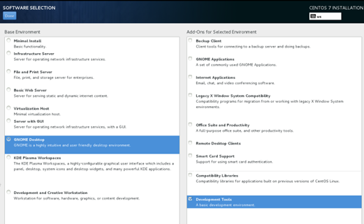
1. After you log in to the VM GUI (see Figure 23), install the guest OS as instructed. In the figure, the GNOME Desktop and Development Tools options are selected. You can make your choice as needed.
Figure 23 VM GUI login initial interface
2. After the guest OS is installed in the VM, right-click on the desktop and select Open Terminal to access the CLI of the Centos 7 system.
3. Shut down the firewall.
At the prompt for a password, enter the password you set when you installed the OS.
[centos7@localhost~]# su
password:
[root@localhost~]# sudo systemctl stop firewalld
Configuring VM network settings
Manual VM deployment uses the same VM network setup procedure as the automatic deployment.
To configure the network settings of a VM:
Managing and maintaining VMs
After you deploy a VM, you can use commands to manage and maintain the VM or display information about the VM.
This document contains only basic VM configuration and commands. For more information about VM configuration and commands, see the following documents:
· VM configuration in Virtual Technologies Configuration Guide of H3C SR6602-I[IE] AI-Powered ICT Converged Gateways Configuration Guides.
· VM commands in Virtual Technologies Command Reference of H3C SR6602-I[IE] AI-Powered ICT Converged Gateways Command References.
Managing VMs
Starting a VM
1. In system view, enter VMM view.
<Sysname> system-view
[Sysname] vmm
2. Start a VM. For example, start VM centos7.
[Sysname-vmm] virsh start centos7
Shutting down a VM
About this task
Shutting down a VM takes about 2 minutes.
If a VM cannot shut down normally, forcibly shut it down as described in "Forcibly shutting down a VM."
Procedure
1. In system view, enter VMM view.
<Sysname> system-view
[Sysname] vmm
2. Shut down a VM. For example, shut down VM centos7.
[Sysname-vmm] virsh shutdown centos7
Forcibly shutting down a VM
About this task
If a VM cannot shut down within 2 minutes, forcibly shut down it.
If you cannot shut down the VM from the CLI, use the power button on the converged gateway to power off and then power on the system.
Procedure
1. In system view, enter VMM view.
<Sysname> system-view
[Sysname] vmm
2. Forcibly shut down a VM. For example, shut down VM centos7.
[Sysname-vmm] virsh destroy centos7
Configuring VM auto-start
About this task
This feature enables a VM to automatically start up when the converged gateway starts up.
Procedure
1. In system view, enter VMM view.
<Sysname> system-view
[Sysname] vmm
2. Configure auto-start for a VM:
¡ Enable auto-start for a VM. For example, enable auto-start for VM centos7.
[Sysname-vmm] virsh autostart centos7
¡ Disable auto-start for a VM. For example disable auto-start for VM centos7.
[Sysname-vmm] virsh autostart centos7 --disable
Creating a snapshot of a VM
About this task
Take a snapshot of a VM to back up its state at a time in point. The first snapshot of a VM is its current snapshot. All subsequent snapshots of the VM are the child snapshots of the first snapshot.
You can restore a VM to the state it was when a snapshot was taken.
Procedure
1. In system view, enter VMM view.
<Sysname> system-view
[Sysname] vmm
2. Create a snapshot of a VM. For example, create a snapshot of VM centos7.
[Sysname-vmm] virsh snapshot-create-as centos7 --name centos7.bak.1 --description excemple
Restoring a VM from a snapshot
1. In system view, enter VMM view.
<Sysname> system-view
[Sysname] vmm
2. Restore a VM from a snapshot. For example, restore VM centos7.
[Sysname-vmm] virsh snapshot-revert generic centos7.bak.1
Uninstalling a VM
1. In system view, enter VMM view.
<Sysname> system-view
[Sysname] vmm
2. Uninstall a VM. For example, uninstall VM centos7.
[Sysname-vmm] virsh undefine centos7
Expanding a VM
1. In system view, enter VMM view.
<Sysname> system-view
[Sysname] vmm
2. Create a disk file. The file system format is QCOW2, the name is centos7.qcow2, and the size is 30 GB.
<Sysname> system-view
[Sysname] vmm
[Sysname-vmm] qemu-img create -f qcow2 /mnt/sda1:/centos7.qcow2 30G
3. Attach the disk file to a VM, for example, to VM centos7. Set the disk name to vdb and the bus type to virtio.
<Sysname> system-view
[Sysname] vmm
[Sysname-vmm] virsh attach-disk centos7 /mnt/sda1:/centos7.qcow2 vdb --targetbus virtio --subdriver qcow2 --type disk --config
Display and maintenance commands for VM management
Execute display commands in any view.
|
Command |
|
|
Display information about SR-IOV VFs. |
display domain-sriov-vf domain-name |
|
Display VM capability information. |
display ict mode |
|
Display the MAC addresses reserved for MacVTap NICs. |
display mac-for-vmminterface |
|
Display the PCIe addresses of SR-IOV VFs. |
display sriov-vf-pciaddr |
|
Display the number of CPU cores allocated to the VM plane. |
display vcpu-pool |
|
Display the amount of memory allocated to the VM plane. |
display vmem-pool |
|
Display physical NIC information. |
ifconfig [ -a ] [ -v ] [ -s ] < interface > |
|
Display detailed physical NIC information. |
ip link show [ DEVICE ] |
|
Display detailed information about a disk file. |
qemu-img info filename |
|
Display detailed information about a VM. |
virsh dominfo < domain > |
|
Display disk file information for a VM. |
virsh domblklist < domain > [ --inactive ] [ --details ] |
|
Display MacVTap NIC information for a VM. |
virsh domiflist < domain > [ --inactive ] |
|
Display VMs. |
virsh list [ --all ] [ --autostart ] [ --inactive ] [ --no-autostart ] |
|
Display the current snapshot of a VM. |
virsh snapshot-current < domain > [ --name ] |
|
Display all snapshots of a VM. |
virsh snapshot-list < domain > |
|
Display the number of vCPU cores allocated to a VM. |
virsh vcpucount < domain > [ --maximum ] [ --active ] [ --live ] [ --config ] |
|
Display detailed information about vCPU cores for a VM. |
virsh vcpuinfo < domain > [ --pretty ] |
|
Display the bindings between vCPU cores and physical CPU cores for a VM. |
virsh vcpupin < domain > [ --vcpu < number > ] [ --cpulist < string > ] [ --config ] [ --live ] |
|
Display the VNC port number of a VM. |
virsh vncdisplay < domain > |
