- Table of Contents
- Related Documents
-
| Title | Size | Download |
|---|---|---|
| 01-H3C S12500 MDC Configuration Examples | 199.55 KB |
General configuration restrictions and guidelines
Example: Configuring MDCs in standalone mode
Configuration restrictions and guidelines
Example: Configuring MDCs in IRF mode
Introduction
This document provides examples for configuring multitenant device contexts (MDCs) on the switch.
You can use H3C MDC technology to virtualize the switch into multiple logical devices called MDCs. Each MDC uses its own hardware and software resources, and operates and forwards packets independently. From the user's perspective, an MDC is a standalone physical device.
Prerequisites
The configuration examples in this document were created and verified in a lab environment, and all the devices were started with the factory default configuration. When you are working on a live network, make sure you understand the potential impact of every command on your network.
This document assumes that you have basic knowledge of H3C MDC.
General configuration restrictions and guidelines
When you configure MDCs, follow these general restrictions and guidelines:
· You must install a valid license to use the MDC feature.
· You can create MDCs only on MPUs with a memory space that is equal to or greater than 4 GB.
· The enhanced IRF mode and the MDC feature are mutually exclusive.
· A non-default MDC is not started by default. It runs only after you start it.
· The management Ethernet interface is shared by all MDCs. Each of the other physical interfaces can belong only to one MDC. After you assign a physical interface to an MDC, you can configure the interface only after you log in to the MDC.
· Because of hardware restrictions, the interfaces on some LPUs are grouped. The interfaces in a group must be assigned to or removed from the same MDC at the same time. To figure out whether and how the interfaces are grouped, view the output of the allocate interface or undo allocate interface command. If the following conditions are not met, the command displays the interfaces that failed to be assigned and the interfaces in the same group or groups:
¡ The interfaces specified for the command belong to the same group or groups.
¡ You have specified all interfaces in the group or groups for the command.
For example, an LPU has 48 interfaces. Interfaces 1 through 24 belong to one group, and interfaces 25 through 48 belong to another group.
Table 1 Interface assignment examples
|
Interfaces specified for the command |
Result |
|
1 through 10 |
The assignment failed. A message displays that interfaces 1 through 24 belong to the same group. |
|
1 through 24 or 25 through 48 |
The assignment succeeded. The switch does not display any messages. |
|
1 through 30 |
Interfaces 1 through 24 were assigned the MDC successfully. The assignment failed for interfaces 25 through 30. A message displays that interfaces 25 through 48 belong to the same group. |
|
1 through 48 |
The assignment succeeded. The switch does not display any messages. |
Example: Configuring MDCs in standalone mode
Network requirements
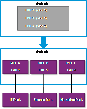
As shown in Figure 1, the switch has three LPUs. Each LPU has 48 Ethernet interfaces. The company has three departments:
· The IT department is responsible for the data center. The data center has servers and storage devices.
· The finance department has higher network availability and security requirements than the other departments.
· The marketing department has less Internet traffic than the other departments.
Configure three MDCs on the switch as shown in Table 2 to meet the Internet access requirements of the three departments.
Table 2 CPU, disk space, and memory space quotas for MDCs
|
MDC |
CPU weight |
Disk space quota |
Memory space quota |
|
MDC A |
10 (default) |
60% |
70% |
|
MDC B |
10 (default) |
50% |
60% |
|
MDC C |
5 |
40% |
50% |
Software version used
This configuration example was created and verified on S12500-CMW710-R7328P02.
Configuration restrictions and guidelines
When you configure MDCs, follow these restrictions and guidelines:
· A standalone S12500 that uses LST1MRPNE1 or LST1MRPNE2 MPUs supports up to eight non-default MDCs.
· A standalone S12500 that uses LST1MRPNC1 MPUs supports up to three non-default MDCs.
Configuration procedures
1. Assign an IP address to the physical management Ethernet interface. Configure Telnet service to allow remote management of the default MDC.
<Switch> system-view
[Switch] interface M-Ethernet 0/0/0
[Switch-M-Ethernet0/0/0] ip address 192.168.0.250 16
[Switch-M-Ethernet0/0/0] quit
[Switch] telnet server enable
[Switch] line vty 0 63
[Switch-line-vty0-63] authentication-mode password
[Switch-line-vty0-63] set authentication password simple 123
[Switch-line-vty0-63] user-role network-admin
[Switch-line-vty0-63] quit
2. Create and configure MDC A for the IT department:
# Create MDC A.
[Switch] mdc MDCA
It will take some time to create MDC...
This MDC was created successfully.
# Authorize MDC A to use LPU 2.
[Switch-mdc-2-MDCA] location slot 2
# Assign interfaces GigabitEthernet 2/0/1 through GigabitEthernet 2/0/48 to MDC A.
[Switch-mdc-2-MDCA] allocate interface GigabitEthernet 2/0/1 to GigabitEthernet 2/0/48
The configurations of the interfaces will be lost. Continue? [Y/N]:y
# Set the disk space quota on the MPU in slot 1 to 60%.
[Switch-mdc-2-MDCA] limit-resource disk slot 1 ratio 60
# Set the memory space quota on the MPU in slot 1 to 70%.
[Switch-mdc-2-MDCA] limit-resource memory slot 1 ratio 70
# Start MDC A.
[Switch-mdc-2-MDCA] mdc start
It will take some time to start MDC...
This MDC was started successfully.
[Switch-mdc-2-MDCA] quit
# Switch to MDC A.
[Switch] switchto mdc MDCA
******************************************************************************
* Copyright (c) 2004-2014 Hangzhou H3C Tech. Co., Ltd. All rights reserved. *
* Without the owner's prior written consent, *
* no decompiling or reverse-engineering shall be allowed. *
******************************************************************************
<H3C> system-view
# Change the device name to MDCA for simple MDC identification.
[H3C] sysname MDCA
# Assign an IP address to the virtual management Ethernet interface for MDC A and configure Telnet service to enable remote management of MDC A.
[MDCA] interface M-Ethernet 0/0/0
[MDCA-M-Ethernet0/0/0] ip address 192.168.1.251 24
[MDCA-M-Ethernet0/0/0] quit
[MDCA] telnet server enable
[MDCA] line vty 0 63
[MDCA-line-vty0-63] authentication-mode password
[MDCA-line-vty0-63] set authentication password simple 123
[MDCA-line-vty0-63] user-role mdc-admin
# Return to the default MDC.
[MDCA-line-vty0-63] return
<MDCA> switchback
[Switch]
3. Create and configure MDC B for the finance department:
# Create MDC B.
[Switch] mdc MDCB
It will take some time to create MDC...
This MDC was created successfully.
# Authorize MDC B to use LPU 3.
[Switch-mdc-3-MDCB] location slot 3
# Assign interfaces GigabitEthernet 3/0/1 through GigabitEthernet 3/0/48 to MDC B.
[Switch-mdc-3-MDCB] allocate interface GigabitEthernet 3/0/1 to GigabitEthernet 3/0/48
The configurations of the interfaces will be lost. Continue? [Y/N]:y
# Set the disk space quota on the MPU in slot 1 to 50%.
[Switch-mdc-3-MDCB] limit-resource disk slot 1 ratio 50
# Set the memory space quota on the MPU in slot 1 and LPU 3 to 60%.
[Switch-mdc-3-MDCB] limit-resource memory slot 1 ratio 60
# Start MDC B.
[Switch-mdc-3-MDCB] mdc start
It will take some time to start MDC...
This MDC was started successfully.
[Switch-mdc-3-MDCB] quit
# Switch to MDC B.
[Switch] switchto mdc MDCB
******************************************************************************
* Copyright (c) 2004-2014 Hangzhou H3C Tech. Co., Ltd. All rights reserved. *
* Without the owner's prior written consent, *
* no decompiling or reverse-engineering shall be allowed. *
******************************************************************************
<H3C> system-view
# Change the device name to MDCB for simple MDC identification.
[H3C] sysname MDCB
# Assign an IP address to the virtual management Ethernet interface for MDC B and configure Telnet service to enable remote management of MDC B.
[MDCB] interface M-Ethernet 0/0/0
[MDCB-M-Ethernet0/0/0] ip address 192.168.2.251 24
[MDCB-M-Ethernet0/0/0] quit
[MDCB] telnet server enable
[MDCB] line vty 0 63
[MDCB-line-vty0-63] authentication-mode password
[MDCB-line-vty0-63] set authentication password simple 123
# Return to the default MDC.
[MDCB-line-vty0-63] return
<MDCB> switchback
[Switch]
4. Create and configure MDC C for the marketing department:
# Create MDC C.
[Switch] mdc MDCC
It will take some time to create MDC...
This MDC was created successfully.
# Authorize MDC C to use LPU 4.
[Switch-mdc-4-MDCC] location slot 4
# Assign interfaces GigabitEthernet 4/0/1 through GigabitEthernet 4/0/48 to MDC C.
[Switch-mdc-4-MDCC] allocate interface GigabitEthernet 4/0/1 to GigabitEthernet 4/0/48
The configurations of the interfaces will be lost. Continue? [Y/N]:y
# Set the CPU weight to 5.
[Switch-mdc-4-MDCC] limit-resource cpu weight 5
# Set the disk space quota on the MPU in slot 1 to 40% .
[Switch-mdc-4-MDCC] limit-resource disk slot 1 ratio 40
# Set the memory space quota on the MPU in slot 1 and LPU 4 to 50% .
[Switch-mdc-4-MDCC] limit-resource memory slot 1 ratio 50
# Start MDC C.
[Switch-mdc-4-MDCC] mdc start
It will take some time to start MDC...
This MDC was started successfully.
[Switch-mdc-4-MDCC] quit
# Switch to MDC C.
[Switch] switchto mdc MDCC
******************************************************************************
* Copyright (c) 2004-2014 Hangzhou H3C Tech. Co., Ltd. All rights reserved. *
* Without the owner's prior written consent, *
* no decompiling or reverse-engineering shall be allowed. *
******************************************************************************
Automatic configuration is running, press CTRL_D to break or press CTRL_B to
switch back to the default MDC.
<H3C> system-view
# Change the device name to MDCC for simple MDC identification.
[H3C] sysname MDCC
# Assign an IP address to the virtual management Ethernet interface for MDC C and configure Telnet service to enable remote management of MDC C.
[MDCC] interface M-Ethernet 0/0/0
[MDCC-M-Ethernet0/0/0] ip address 192.168.3.251 24
[MDCC-M-Ethernet0/0/0] quit
[MDCC] telnet server enable
[MDCC] line vty 0 63
[MDCC-line-vty0-63] authentication-mode password
[MDCC-line-vty0-63] set authentication password simple 123
[MDCC-line-vty0-63] user-role mdc-admin
# Return to the default MDC.
[MDCC-line-vty0-63] return
<MDCC> switchback
# Save the running configuration for all MDCs.
[Switch] save mdc-all
Verifying the configuration
1. On the default MDC, identify whether the MDCs exist and are operating correctly.
<Switch> display mdc
ID Name Status
----------------------------------
1 Admin active
2 MDCA active
3 MDCB active
4 MDCC active
The output shows that the MDCs have been created and are in active state.
2. On the default MDC, display the CPU, disk space, and memory space quotas and usage of the MDCs.
<Switch> display mdc resource
Memory:
Slot 1:
Used 235.9MB, Free 3174.4MB, Total 3410.3MB:
ID Name Quota(MB) Used(MB) Available(MB)
----------------------------------------------------------------
1 Admin 3410.3 159.3 3174.4
2 MDCA 2387.2 25.7 2361.6
3 MDCB 2046.2 25.5 2020.7
4 MDCC 1705.2 25.5 1679.7
Slot 2:
Used 20.7MB, Free 735.5MB, Total 756.1MB:
ID Name Quota(MB) Used(MB) Available(MB)
----------------------------------------------------------------
1 Admin 756.1 14.6 735.5
2 MDCA 529.3 6.1 523.2
Slot 3:
Used 19.8MB, Free 736.3MB, Total 756.1MB:
ID Name Quota(MB) Used(MB) Available(MB)
----------------------------------------------------------------
1 Admin 756.1 14.2 736.3
3 MDCB 453.7 5.6 448.1
Slot 4:
Used 19.9MB, Free 736.3MB, Total 756.1MB:
ID Name Quota(MB) Used(MB) Available(MB)
----------------------------------------------------------------
1 Admin 756.1 14.3 736.3
4 MDCC 378.1 5.6 372.5
CPU:
Slot 1:
ID Name Weight Usage(%)
-------------------------------------------------
1 Admin 10 0
2 MDCA 10 0
3 MDCB 10 0
4 MDCC 5 0
Slot 2:
ID Name Weight Usage(%)
-------------------------------------------------
1 Admin 10 2
2 MDCA 10 0
Slot 3:
ID Name Weight Usage(%)
-------------------------------------------------
1 Admin 10 11
3 MDCB 10 0
Slot 4:
ID Name Weight Usage(%)
-------------------------------------------------
1 Admin 10 4
4 MDCC 5 0
Disk:
Slot 1:
cfa0:: Used 573.8MB, Free 422.4MB, Total 996.2MB:
ID Name Quota(MB) Used(MB) Available(MB)
--------------------------------------------------------------
1 Admin 996.2 573.7 422.4
2 MDCA 597.7 0.0 422.4
3 MDCB 498.1 0.0 422.4
4 MDCC 498.1 0.0 422.4
Configuration files
· Default MDC:
#
mdc MDCA id 2
location slot 2
limit-resource memory slot 1 ratio 70
limit-resource disk slot 1 ratio 60
mdc start
allocate interface GigabitEthernet2/0/1 to GigabitEthernet2/0/48
#
mdc MDCB id 3
location slot 3
limit-resource memory slot 1 ratio 60
limit-resource disk slot 1 ratio 50
mdc start
allocate interface GigabitEthernet3/0/1 to GigabitEthernet3/0/48
#
mdc MDCC id 4
location slot 4
limit-resource memory slot 1 ratio 50
limit-resource cpu weight 5
limit-resource disk slot 1 ratio 40
mdc start
allocate interface GigabitEthernet4/0/1 to GigabitEthernet4/0/48
#
telnet server enable
#
interface M-Ethernet0/0/0
ip address 192.168.0.250 255.255.0.0
#
line vty 0 63
user-role network-admin
user-role network-operator
set authentication password hash $h$6$4WJkKacKhE7V9va/$zLfChFIvGQqPQlaSKoI2+PVa
0LYVTjxOjmrbP6GuUycHkt JBJFBuQAEeyWlkCOjKT7hpwihoV1aDNCA7bcO4dg==
#
· MDC A:
#
sysname MDCA
#
telnet server enable
#
interface M-Ethernet0/0/0
ip address 192.168.1.251 255.255.255.0
#
line vty 0 63
user-role mdc-admin
user-role mdc-operator
set authentication password hash $h$6$1Osndewbt1Fewtj/$zLfChFIvGQqPQlaSKoI2+PVa
0LYVTjxOjmrbP6GuUycHkt9U+0qflSvZxRlQLGMBRZhpwihoV1aDNCA7bcO4dg==
#
· MDC B:
#
sysname MDCB
#
telnet server enable
#
interface M-Ethernet0/0/0
ip address 192.168.2.251 255.255.255.0
#
line vty 0 63
user-role mdc-admin
user-role mdc-operator
set authentication password hash $h$6$4k3XflRf/A83ufs3$VubOg+oDeKKcIgD2BGZuErPH
pMrJcCcAeaRc30ph3EMpZjPPru0np/ALpwJBJFBuQAEeyWlkCOjKT7UQR7Z5Zg==
#
· MDC C:
#
sysname MDCC
#
telnet server enable
#
interface M-Ethernet0/0/0
ip address 192.168.3.251 255.255.255.0
#
line vty 0 63
user-role mdc-admin
user-role mdc-operator
set authentication password hash $h$6$4WJkKacKhE7V9vaV$1m7x89d3QBjOpyFoEOCGhWxr
t+eF/wUeRJYAwdwFls/XlyTKuEgBJ4r3lWDzPfrr5nI4qHDk47gAhVhQu7uuQg==
#
Example: Configuring MDCs in IRF mode
Network requirements
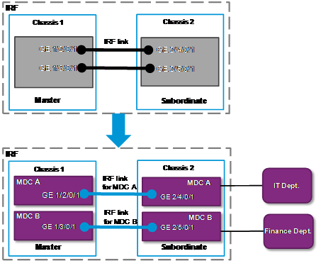
As shown in Figure 2, the IRF fabric has two members. Each member has two LPUs. Each LPU has 48 Ethernet interfaces. Two IRF links are established between the two members.
The company wants to use the IRF fabric to meet the Internet access requirements of two departments:
· The IT department is responsible for the data center. The data center has servers and storage devices.
· The finance department has higher network availability and security requirements but less Internet traffic than the IT department.
Configure two MDCs on the IRF fabric as shown in Table 3 to meet the Internet access requirements.
Table 3 CPU, disk space, and memory space quotas for MDCs
|
MDC |
CPU weight |
Disk space quota |
Memory space quota |
|
MDC A |
10 (default) |
60% |
70% |
|
MDC B |
6 |
50% |
55% |
Requirements analysis
Both MDC A and MDC B are across chassis. To allow MDCs across chassis to forward traffic correctly, you must establish a minimum of one IRF link for each MDC. H3C recommends that you establish two IRF links for each MDC to implement redundancy and load sharing.
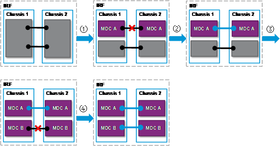
Assigning an LPU that has an IRF link established closes the IRF link. To avoid IRF fabric split, make sure a minimum of one IRF link is operating correctly during the configuration process, as shown in Figure 3.
Figure 3 Correct configuration order
|
1. Assign all interfaces on LPUs 2 and 4 to MDC A. |
2. Establish a new IRF link on MDC A. |
|
3. Assign all interfaces on LPUs 3 and 5 to MDC B. |
4. Establish a new IRF link on MDC B. |
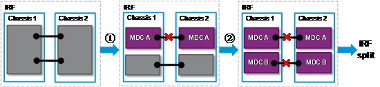
Figure 4 Incorrect configuration order
|
1. Assign all interfaces on LPUs 2 and 4 to MDC A. |
2. Assign all interfaces on LPUs 3 and 5 to MDC B. |
Software version used
This configuration example was created and verified on S12500-CMW710-R7328P02.
Configuration restrictions and guidelines
When you configure MDCs, follow these restrictions and guidelines:
· An IRF fabric that uses LST1MRPNE1 or LST1MRPNE2 MPUs supports up to eight non-default MDCs.
· An IRF fabric that uses LST1MRPNC1 MPUs supports up to three non-default MDCs.
· To configure both IRF and MDCs on a switch, configure IRF first. The switch will reboot and load the master's configuration rather than its own when it joins an IRF fabric as a subordinate member. None of its settings except for the IRF port settings will take effect. The IRF members in this example have been configured and have formed an IRF fabric.
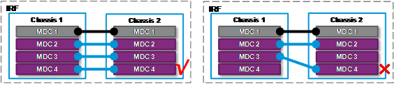
· The physical IRF ports of an IRF link must belong to the same MDC. If they do not, the link cannot be established and forwarding errors might occur, as shown in Figure 5.
Figure 5 The physical IRF ports of an IRF link must belong to the same MDC
· To assign a physical IRF port to or reclaim a physical IRF port from an MDC , follow these steps:
a. Use the shutdown command to shut down the port.
b. Use the undo port group interface command to remove the IRF port-physical IRF port binding.
c. Assign or reclaim the physical IRF port.
d. Use the save command to save the running configuration.
To avoid IRF fabric split, make sure a minimum of one IRF link is operating correctly during this process.
Configuration procedures
1. Assign an IP address to the management Ethernet interface for the IRF fabric. Configure Telnet service to allow remote management of the default MDC.
<IRF> system-view
[IRF] interface M-Ethernet 1/0/0/0
[IRF-M-Ethernet1/0/0/0] ip address 192.168.0.250 16
[IRF-M-Ethernet1/0/0/0] quit
[IRF] telnet server enable
[IRF] line vty 0 63
[IRF-line-vty0-63] authentication-mode password
[IRF-line-vty0-63] set authentication password simple 123456
[IRF-line-vty0-63] user-role network-admin
[IRF-line-vty0-63] quit
2. Create and configure MDC A for the IT department:
# Shut down physical IRF ports GE 1/2/0/1 and GE 2/4/0/1 and remove the IRF port-physical IRF port binding.
<IRF> system-view
[IRF] interface GigabitEthernet 1/2/0/1
[IRF-GigabitEthernet1/2/0/1] shutdown
[IRF-GigabitEthernet1/2/0/1] quit
[IRF] irf-port 1/1
[IRF-irf-port1/1] undo port group mdc 1 interface GigabitEthernet1/2/0/1
[IRF-irf-port1/1] quit
[IRF] interface GigabitEthernet 2/4/0/1
[IRF-GigabitEthernet2/4/0/1] shutdown
[IRF-GigabitEthernet2/4/0/1] quit
[IRF] irf-port 2/2
[IRF-irf-port2/2] undo port group mdc 1 interface GigabitEthernet2/4/0/1
[IRF-irf-port2/2] save
# Create MDC A.
<IRF> system-view
[IRF] mdc MDCA
It will take some time to create MDC...
This MDC was created successfully.
# Assign LPU 2 (on the master) and LPU 4 (on the subordinate member) to MDC A.
[IRF-mdc-2-MDCA] location chassis 1 slot 2
[IRF-mdc-2-MDCA] location chassis 2 slot 4
# Assign interface GE 1/2/0/1 through GE 1/2/0/48 and GE 2/4/0/1 through GE 2/4/0/48 to MDC A.
[IRF-mdc-2-MDCA] allocate interface GigabitEthernet 1/2/0/1 to GigabitEthernet 1/2/0/48
The configurations of the interfaces will be lost. Continue? [Y/N]:y
[IRF-mdc-2-MDCA] allocate interface GigabitEthernet 2/4/0/1 to GigabitEthernet 2/4/0/48
The configurations of the interfaces will be lost. Continue? [Y/N]:y
# Set the disk space quota on each MPU to 60%.
[IRF-mdc-2-MDCA] limit-resource disk chassis 1 slot 0 ratio 60
[IRF-mdc-2-MDCA] limit-resource disk chassis 1 slot 1 ratio 60
[IRF-mdc-2-MDCA] limit-resource disk chassis 2 slot 0 ratio 60
[IRF-mdc-2-MDCA] limit-resource disk chassis 2 slot 1 ratio 60
# Set the memory space quota on each MPU and each LPU for MDC A to 70%.
[IRF-mdc-2-MDCA] limit-resource memory chassis 1 slot 0 ratio 70
[IRF-mdc-2-MDCA] limit-resource memory chassis 1 slot 1 ratio 70
[IRF-mdc-2-MDCA] limit-resource memory chassis 1 slot 2 ratio 70
[IRF-mdc-2-MDCA] limit-resource memory chassis 2 slot 0 ratio 70
[IRF-mdc-2-MDCA] limit-resource memory chassis 2 slot 1 ratio 70
[IRF-mdc-2-MDCA] limit-resource memory chassis 2 slot 4 ratio 70
# Start MDC A.
[IRF-mdc-2-MDCA] mdc start
It will take some time to start MDC...
This MDC was started successfully.
[IRF-mdc-2-MDCA] quit
# Bind IRF port 1/1 to physical IRF ports GE 1/2/0/1 and GE 1/2/0/2. Bind IRF port 2/2 to physical IRF ports GE 2/4/0/1 and GE 2/4/0/2.
[IRF] irf-port 1/1
[IRF-irf-port1/1] port group mdc 2 interface GigabitEthernet 1/2/0/1
[IRF-irf-port1/1] port group mdc 2 interface GigabitEthernet 1/2/0/2
[IRF-irf-port1/1] quit
[IRF] irf-port 2/2
[IRF-irf-port2/2] port group mdc 2 interface GigabitEthernet 2/4/0/1
[IRF-irf-port2/2] port group mdc 2 interface GigabitEthernet 2/4/0/2
[IRF-irf-port2/2] quit
# Switch to MDC A and bring up the physical IRF ports.
[IRF] switchto mdc MDCA
******************************************************************************
* Copyright (c) 2004-2014 Hangzhou H3C Tech. Co., Ltd. All rights reserved. *
* Without the owner's prior written consent, *
* no decompiling or reverse-engineering shall be allowed. *
******************************************************************************
<MDCA> system-view
[MDCA] interface GigabitEthernet 1/2/0/1
[MDCA-GigabitEthernet1/2/0/1] undo shutdown
[MDCA-GigabitEthernet1/2/0/1] quit
[MDCA] interface GigabitEthernet 1/2/0/2
[MDCA-GigabitEthernet1/2/0/2] undo shutdown
[MDCA-GigabitEthernet1/2/0/2] quit
[MDCA] interface GigabitEthernet 2/4/0/1
[MDCA-GigabitEthernet2/4/0/1] undo shutdown
[MDCA-GigabitEthernet2/4/0/1] quit
[MDCA] interface GigabitEthernet 2/4/0/2
[MDCA-GigabitEthernet2/4/0/2] undo shutdown
[MDCA-GigabitEthernet2/4/0/2] quit
# Change the device name to MDCA for simple MDC identification.
[IRF] sysname MDCA
# Assign an IP address to the virtual management Ethernet interface for MDC A and configure Telnet service to enable remote management of MDC A.
[MDCA] interface M-Ethernet 1/0/0/0
[MDCA-M-Ethernet1/0/0/0] ip address 192.168.1.251 24
[MDCA-M-Ethernet1/0/0/0] quit
[MDCA] telnet server enable
[MDCA] line vty 0 63
[MDCA-line-vty0-63] authentication-mode password
[MDCA-line-vty0-63] set authentication password simple 123456
[MDCA-line-vty0-63] user-role mdc-admin
# Return to the default MDC.
[MDCA-line-vty0-63] return
<MDCA> switchback
[IRF]
3. Create and configure MDC B for the finance department:
# Shut down physical IRF ports GE 1/3/0/1 and GE 2/5/0/1 and remove the IRF port-physical IRF port binding.
<IRF> system-view
[IRF] interface GigabitEthernet 1/3/0/1
[IRF-GigabitEthernet1/3/0/1] shutdown
[IRF-GigabitEthernet1/3/0/1] quit
[IRF] irf-port 1/2
[IRF-irf-port1/2] undo port group mdc 1 interface GigabitEthernet1/3/0/1
[IRF-irf-port1/2] quit
[IRF] interface GigabitEthernet 2/5/0/1
[IRF-GigabitEthernet2/5/0/1] shutdown
[IRF-GigabitEthernet2/5/0/1] quit
[IRF] irf-port 2/1
[IRF-irf-port2/1] undo port group mdc 1 interface GigabitEthernet2/5/0/1
[IRF-irf-port2/1] save
# Create MDC B.
[IRF] mdc MDCB
It will take some time to create MDC...
This MDC was created successfully.
# Assign LPU 3 (on the master) and LPU 5 (on the subordinate member) to MDC B.
[IRF-mdc-3-MDCB] location chassis 1 slot 3
[IRF-mdc-3-MDCB] location chassis 2 slot 5
# Assign interface GE 1/3/0/1 through GE 1/3/0/48 and GE 2/5/0/1 through GE 2/5/0/48 to MDC B.
[IRF-mdc-3-MDCB] allocate interface GigabitEthernet 1/3/0/1 to GigabitEthernet 1/3/0/48
The configurations of the interfaces will be lost. Continue? [Y/N]:y
[IRF-mdc-3-MDCB] allocate interface GigabitEthernet 2/5/0/1 to GigabitEthernet 2/5/0/48
The configurations of the interfaces will be lost. Continue? [Y/N]:y
# Set the CPU weight to 6.
[IRF-mdc-3-MDCB] limit-resource cpu weight 6
# Set the disk space quota on each MPU to 50%.
[IRF-mdc-3-MDCB] limit-resource disk chassis 1 slot 0 ratio 50
[IRF-mdc-3-MDCB] limit-resource disk chassis 1 slot 1 ratio 50
[IRF-mdc-3-MDCB] limit-resource disk chassis 2 slot 0 ratio 50
[IRF-mdc-3-MDCB] limit-resource disk chassis 2 slot 1 ratio 50
# Set the memory space quota on each MPU and each LPU for MDC B to 55%.
[IRF-mdc-3-MDCB] limit-resource memory chassis 1 slot 0 ratio 55
[IRF-mdc-3-MDCB] limit-resource memory chassis 1 slot 1 ratio 55
[IRF-mdc-3-MDCB] limit-resource memory chassis 1 slot 3 ratio 55
[IRF-mdc-3-MDCB] limit-resource memory chassis 2 slot 0 ratio 55
[IRF-mdc-3-MDCB] limit-resource memory chassis 2 slot 1 ratio 55
[IRF-mdc-3-MDCB] limit-resource memory chassis 2 slot 5 ratio 55
# Start MDC B.
[IRF-mdc-3-MDCB] mdc start
It will take some time to start MDC...
This MDC was started successfully.
[IRF-mdc-3-MDCB] quit
# Bind IRF port 1/1 to physical IRF ports GE 1/3/0/1 and GE 1/3/0/2. Bind IRF port 2/2 to physical IRF ports GE 2/5/0/1 and GE 2/5/0/2.
[IRF] irf-port 1/1
[IRF-irf-port1/1] port group mdc 3 interface GigabitEthernet 1/3/0/1
[IRF-irf-port1/1] port group mdc 3 interface GigabitEthernet 1/3/0/2
[IRF-irf-port1/1] quit
[IRF] irf-port 2/2
[IRF-irf-port2/2] port group mdc 3 interface GigabitEthernet 2/5/0/1
[IRF-irf-port2/2] port group mdc 3 interface GigabitEthernet 2/5/0/2
[IRF-irf-port2/2] quit
# Switch to MDC B and bring up the physical IRF ports.
[IRF]switchto mdc MDCA
******************************************************************************
* Copyright (c) 2004-2014 Hangzhou H3C Tech. Co., Ltd. All rights reserved. *
* Without the owner's prior written consent, *
* no decompiling or reverse-engineering shall be allowed. *
******************************************************************************
<MDCB> system-view
[MDCB] interface GigabitEthernet 1/3/0/1
[MDCB-GigabitEthernet1/3/0/1] undo shutdown
[MDCB-GigabitEthernet1/3/0/1] quit
[MDCB] interface GigabitEthernet 1/3/0/2
[MDCB-GigabitEthernet1/3/0/2] undo shutdown
[MDCB-GigabitEthernet1/3/0/2] quit
[MDCB] interface GigabitEthernet 2/5/0/1
[MDCB-GigabitEthernet2/5/0/1] undo shutdown
[MDCB-GigabitEthernet2/5/0/1] quit
[MDCB] interface GigabitEthernet 2/5/0/2
[MDCB-GigabitEthernet2/5/0/2] undo shutdown
[MDCB-GigabitEthernet2/5/0/2] quit
# Change the device name to MDCB for simple MDC identification.
[IRF] sysname MDCB
# Assign an IP address to the virtual management Ethernet interface for MDC B and configure Telnet service to enable remote management of MDC B.
[MDCB] interface M-Ethernet 1/0/0/0
[MDCB-M-Ethernet1/0/0/0] ip address 192.168.2.251 24
[MDCB-M-Ethernet1/0/0/0] quit
[MDCB] telnet server enable
[MDCB] line vty 0 63
[MDCB-line-vty0-63] authentication-mode password
[MDCB-line-vty0-63] set authentication password simple 123456
[MDCB-line-vty0-63] user-role mdc-admin
[MDCB-line-vty0-63] return
# Save the running configuration for all MDCs.
<MDCB> save mdc-all
Verifying the configuration
1. On the default MDC, identify whether the MDCs exist and are operating correctly.
<IRF> display mdc
ID Name Status
----------------------------------
1 Admin active
2 MDCA active
3 MDCB active
The output shows that the MDCs have been created and are in active state.
2. On the default MDC, display the CPU, disk space, and memory space quotas and usage of the MDCs.
<IRF> display mdc resource
Memory:
Chassis 1 Slot 0:
Used 200.1MB, Free 3210.2MB, Total 3410.3MB:
ID Name Quota(MB) Used(MB) Available(MB)
----------------------------------------------------------------
1 Admin 3410.3 148.5 3210.2
2 MDCA 2387.2 25.8 2361.4
3 MDCB 1875.7 25.8 1849.9
Chassis 1 Slot 1:
Used 200.1MB, Free 3210.2MB, Total 3410.3MB:
ID Name Quota(MB) Used(MB) Available(MB)
----------------------------------------------------------------
1 Admin 3410.3 148.5 3210.2
2 MDCA 2387.2 25.8 2361.4
3 MDCB 1875.7 25.8 1849.9
Chassis 1 Slot 2:
Used 20.2MB, Free 736.0MB, Total 756.1MB:
ID Name Quota(MB) Used(MB) Available(MB)
----------------------------------------------------------------
1 Admin 756.1 13.0 736.0
2 MDCA 529.3 7.2 522.1
Chassis 1 Slot 3:
Used 19.2MB, Free 736.9MB, Total 756.1MB:
ID Name Quota(MB) Used(MB) Available(MB)
----------------------------------------------------------------
1 Admin 756.1 12.5 736.9
3 MDCB 415.9 6.7 409.2
Chassis 2 Slot 0:
Used 200.1MB, Free 3210.2MB, Total 3410.3MB:
ID Name Quota(MB) Used(MB) Available(MB)
----------------------------------------------------------------
1 Admin 3410.3 148.5 3210.2
2 MDCA 2387.2 25.8 2361.4
3 MDCB 1875.7 25.8 1849.9
Chassis 2 Slot 1:
Used 200.1MB, Free 3210.2MB, Total 3410.3MB:
ID Name Quota(MB) Used(MB) Available(MB)
----------------------------------------------------------------
1 Admin 3410.3 148.5 3210.2
2 MDCA 2387.2 25.8 2361.4
3 MDCB 1875.7 25.8 1849.9
Chassis 2 Slot 4:
Used 19.3MB, Free 736.9MB, Total 756.1MB:
ID Name Quota(MB) Used(MB) Available(MB)
----------------------------------------------------------------
1 Admin 756.1 12.5 736.9
2 MDCA 529.3 6.7 522.6
Chassis 2 Slot 5:
Used 20.1MB, Free 736.1MB, Total 756.1MB:
ID Name Quota(MB) Used(MB) Available(MB)
----------------------------------------------------------------
1 Admin 756.1 14.3 736.1
3 MDCB 415.9 5.7 410.1
CPU:
Chassis 1 Slot 0:
ID Name Weight Usage(%)
-------------------------------------------------
1 Admin 10 0
2 MDCA 10 0
3 MDCB 6 0
Chassis 1 Slot 1:
ID Name Weight Usage(%)
-------------------------------------------------
1 Admin 10 0
2 MDCA 10 0
3 MDCB 6 0
Chassis 1 Slot 2:
ID Name Weight Usage(%)
-------------------------------------------------
1 Admin 10 0
2 MDCA 10 0
Chassis 1 Slot 3:
ID Name Weight Usage(%)
-------------------------------------------------
1 Admin 10 1
3 MDCB 6 0
Chassis 2 Slot 0:
ID Name Weight Usage(%)
-------------------------------------------------
1 Admin 10 0
2 MDCA 10 0
3 MDCB 6 0
Chassis 2 Slot 1:
ID Name Weight Usage(%)
-------------------------------------------------
1 Admin 10 0
2 MDCA 10 0
3 MDCB 6 0
Chassis 2 Slot 4:
ID Name Weight Usage(%)
-------------------------------------------------
1 Admin 10 11
2 MDCA 10 0
Chassis 2 Slot 5:
ID Name Weight Usage(%)
-------------------------------------------------
1 Admin 10 1
3 MDCB 6 0
Disk:
Chassis 1 Slot 0:
cfa0:: Used 574.8MB, Free 421.4MB, Total 996.2MB:
ID Name Quota(MB) Used(MB) Available(MB)
--------------------------------------------------------------
1 Admin 996.2 574.8 421.4
2 MDCA 597.7 0.0 421.4
3 MDCB 498.1 0.0 421.4
Chassis 1 Slot 1:
cfa0:: Used 574.8MB, Free 421.4MB, Total 996.2MB:
ID Name Quota(MB) Used(MB) Available(MB)
--------------------------------------------------------------
1 Admin 996.2 574.8 421.4
2 MDCA 597.7 0.0 421.4
3 MDCB 498.1 0.0 421.4
Chassis 2 Slot 0:
cfa0:: Used 200.2MB, Free 796MB, Total 996.2MB:
ID Name Quota(MB) Used(MB) Available(MB)
--------------------------------------------------------------
1 Admin 996.2 200.2 796
2 MDCA 597.7 0.0 597.7
3 MDCB 498.1 0.0 498.1
Chassis 2 Slot 1:
cfa0:: Used 200.2MB, Free 796MB, Total 996.2MB:
ID Name Quota(MB) Used(MB) Available(MB)
--------------------------------------------------------------
1 Admin 996.2 200.2 796
2 MDCA 597.7 0.0 597.7
3 MDCB 498.1 0.0 498.1
Configuration files
· Default MDC:
#
mdc MDCA id 2
location chassis 1 slot 2
location chassis 2 slot 4
limit-resource memory chassis 1 slot 0 ratio 70
limit-resource memory chassis 1 slot 1 ratio 70
limit-resource memory chassis 1 slot 2 ratio 70
limit-resource memory chassis 2 slot 0 ratio 70
limit-resource memory chassis 2 slot 1 ratio 70
limit-resource memory chassis 2 slot 4 ratio 70
limit-resource disk chassis 1 slot 0 ratio 60
limit-resource disk chassis 1 slot 1 ratio 60
limit-resource disk chassis 2 slot 0 ratio 60
limit-resource disk chassis 2 slot 1 ratio 60
mdc start
allocate interface GigabitEthernet1/2/0/1 to GigabitEthernet1/2/0/48
allocate interface GigabitEthernet2/4/0/1 to GigabitEthernet2/4/0/48
#
mdc MDCB id 3
location chassis 1 slot 3
location chassis 2 slot 5
limit-resource memory chassis 1 slot 0 ratio 55
limit-resource memory chassis 1 slot 1 ratio 55
limit-resource memory chassis 1 slot 3 ratio 55
limit-resource memory chassis 2 slot 0 ratio 55
limit-resource memory chassis 2 slot 1 ratio 55
limit-resource memory chassis 2 slot 5 ratio 55
limit-resource cpu weight 6
limit-resource disk chassis 1 slot 0 ratio 50
limit-resource disk chassis 1 slot 1 ratio 50
limit-resource disk chassis 2 slot 0 ratio 50
limit-resource disk chassis 2 slot 1 ratio 50
mdc start
allocate interface GigabitEthernet1/3/0/1 to GigabitEthernet1/3/0/48
allocate interface GigabitEthernet2/5/0/1 to GigabitEthernet2/5/0/48
#
irf-port 1/1
port group mdc 2 interface GigabitEthernet1/2/0/1
port group mdc 2 interface GigabitEthernet1/2/0/2
port group mdc 3 interface GigabitEthernet1/3/0/1
port group mdc 3 interface GigabitEthernet1/3/0/2
#
irf-port 2/2
port group mdc 2 interface GigabitEthernet2/4/0/1
port group mdc 2 interface GigabitEthernet2/4/0/2
port group mdc 3 interface GigabitEthernet2/5/0/1
port group mdc 3 interface GigabitEthernet2/5/0/2
#
interface GigabitEthernet1/2/0/1
shutdown
#
interface GigabitEthernet1/2/0/2
shutdown
#
interface GigabitEthernet1/3/0/1
shutdown
#
interface GigabitEthernet1/3/0/2
shutdown
#
interface GigabitEthernet2/4/0/1
shutdown
#
interface GigabitEthernet2/4/0/2
shutdown
#
interface GigabitEthernet2/5/0/1
shutdown
#
interface GigabitEthernet2/5/0/2
shutdown
#
telnet server enable
#
interface M-Ethernet1/0/0/0
ip address 192.168.0.250 255.255.0.0
#
line vty 0 63
user-role network-admin
user-role network-operator
set authentication password hash $h$6$4WJkKacKhE7V9va/$zLfChFIvGQqPQlaSKoI2+PVa
0LYVTjxOjmrbP6GuUycHkt JBJFBuQAEeyWlkCOjKT7hpwihoV1aDNCA7bcO4dg==
#
· MDC A:
#
sysname MDCA
#
telnet server enable
#
interface GigabitEthernet1/2/0/1
#
interface GigabitEthernet1/2/0/2
#
interface GigabitEthernet2/4/0/1
#
interface GigabitEthernet2/4/0/2
#
interface M-Ethernet1/0/0/0
ip address 192.168.1.251 255.255.255.0
#
line vty 0 63
user-role mdc-admin
user-role mdc-operator
set authentication password hash $h$6$IP9LagJ2XOEmstrB$q32cAE88NPiiCbTD/Xj9gtsd
g9RIZ2HKYdKoqcEQ9EoM6L5tAX+yMqtCnWjy+lP+6SLNTKUMtXu1zK9poXCvIw==
#
· MDC B:
#
sysname MDCB
#
telnet server enable
#
interface GigabitEthernet1/3/0/1
#
interface GigabitEthernet1/3/0/2
#
interface GigabitEthernet2/5/0/1
#
interface GigabitEthernet2/5/0/2
#
interface M-Ethernet1/0/0/0
ip address 192.168.2.251 255.255.255.0
#
line vty 0 63
user-role mdc-admin
user-role mdc-operator
set authentication password hash $h$6$O5lxVj7UEASC4zgx$oUk9/+uYPN2vYRsllJ+gJQhb
3tK9zU1OTunmpGvKtcPBITr8XvMDZLk3phure4XSdJ/joWxkAAqu2MpxSHaoXw==
#
Related documentation
· H3C S12500 Routing Switch Series Virtual Technologies Configuration Guide-Release 7328
· H3C S12500 Routing Switch Series Virtual Technologies Command Reference-Release 7328
