| Title | Size | Downloads |
|---|---|---|
| H3C S9500E Routing Switch Series Installation Guide-6PW107-Chapter 4 Connecting the Switch to the Network .pdf | 679.89 KB |
- Table of Contents
- Related Documents
-
| Title | Size | Download |
|---|---|---|
| 04-Chapter 4 Connecting the Switch to the Network | 679.89 KB |
Contents
Connecting the switch to the network
Setting up a configuration environment
Connecting the switch to the network
Connecting the switch to the network through an AUX cable
Connecting the switch to the network through an Ethernet twisted pair cable
Connecting the switch to the network through an optical fiber
Connecting the switch to the network
Cable routing recommendations
Interface cables and power cords should be separately routed. Reasonable cable routing can improve efficiency by facilitating installation and removal of fan trays, and some other components.
· Interface cables are routed through the cable management brackets on the left and right sides of the chassis and bound at cabling racks on chassis sides, depending on the available equipment room condition.
· Put all the data signal cable adapters neatly under the chassis (instead of any places outside the chassis in case of unexpected damages).
· The power cords run along the left-rear of the chassis and out of the chassis either from the chassis top or the raised floor depending on the equipment room conditions (power distribution rack, lightning protection box, and connector strip, etc.) of the exchange office.
· Long cables can be bound with cable ties. Do not bind cables at the air exhaust vent to prevent the cables from aging too fast. For more information, see "Appendix E Cable management."
· Fix cables as near the switch as possible. The cables between the fixing point and switch interfaces must be bound loosely.
· To identify cables, you can stick labels on them. For more information, see "Appendix F Engineering labels for cables."
Logging in to the switch
Logging in through the console port is the most common way to log in to a switch. It is also the prerequisite to configuring other login methods.
Connecting the console cable
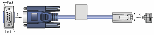
A console cable is an 8-core shielded cable, with a crimped RJ-45 connector at one end for connecting to the console port of the switch, and a DB-9 female connector at the other end for connecting to the serial port on the console terminal.
|
RJ-45 pin |
Signal |
DB-9 pin |
Signal |
|
1 |
RTS |
8 |
CTS |
|
2 |
DTR |
6 |
DSR |
|
3 |
TXD |
2 |
RXD |
|
4 |
CD |
5 |
SG |
|
5 |
GND |
5 |
SG |
|
6 |
RXD |
3 |
TXD |
|
7 |
DSR |
4 |
DTR |
|
8 |
CTS |
7 |
RTS |
Figure 2 Connecting the switch and the PC through the console port
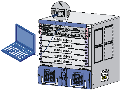
To connect the console cable:
1. Connect the DB-9 connector of the console cable to the serial port of a PC or terminal.
2. Connect the RJ-45 connector of the console cable to the console port of the MPU of the switch.
|
|
NOTE: When you remove the console cable, first unplug the RJ-45 end, and then the DB-9 end. |
Setting up a configuration environment
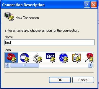
1. Select Start > All Programs > Accessories > Communications > HyperTerminal.
The Connection Description dialog box appears.
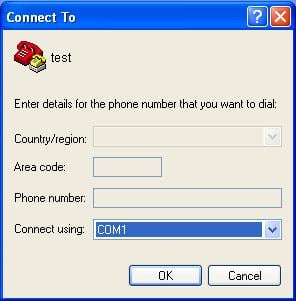
2. Enter the name of the new connection in the Name field and click OK.
Figure 3 Connection description
3. Select the serial port to be used from the Connect using list, and click OK.
Figure 4 Setting the serial port used by the HyperTerminal connection
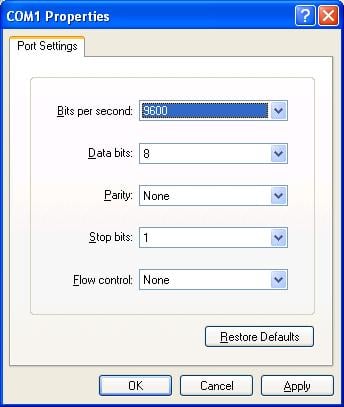
4. Set Bits per second to 9600, Data bits to 8, Parity to None, Stop bits to 1, and Flow control to None, and click OK.
Figure 5 Setting the serial port parameters
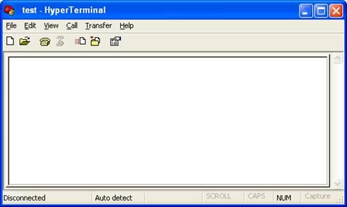
5. Select File > Properties in the HyperTerminal window.
Figure 6 HyperTerminal window
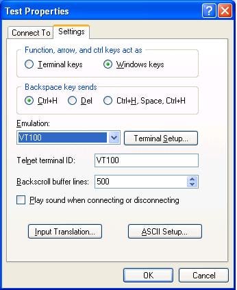
6. On the Settings tab, set the emulation to VT100 and click OK.
|
|
NOTE: H3C recommends that you select the Windows keys option button. |
Figure 7 Setting the terminal emulation in Test Properties dialog box
Powering on the switch
|
|
CAUTION: Before powering on the switch, identify the power switch in the equipment room so that you can disconnect the power supply promptly in case of an emergency. |
Before powering on the switch, verify that:
· The interface cables, power cables and the grounding cable are correctly connected.
· The input power voltage meets the requirement of the switch.
· The console cable is properly connected, the terminal or PC used for configuration has started, and the configuration parameters have been set.
Powering on the switch
1. Turn on the power switch of the power source providing power to the switch.
2. Turn on the power switch on the switch.
Before the switch is powered on, the following information is displayed:
DDR2 SDRAM test successful.
System is starting...
Booting Normal Extend BootWare
The Extend BootWare is self-decompressing..........................
Done!
****************************************************************************
* *
* H3C S9500E BootWare, Version 1.09 *
* *
****************************************************************************
Copyright (c) 2004-2009 Hangzhou H3C Technologies Co., Ltd.
Compiled Date : Jul 22 2009
CPU Type : MPC8548E
CPU L1 Cache : 32KB
CPU L2 Cache : 512KB
CPU Clock Speed : 1000MHz
Memory Type : DDR2 SDRAM
Memory Size : 1024MB
Memory Speed : 400MHz
BootWare Size : 4MB
Flash Size : 128MB
cfa0 Size : 247MB
NVRAM Size : 1024KB
BASIC CPLD Version : 001F
EXTEND CPLD Version : 001F
PCB Version : Ver.B
The switch initiates the power-on self-test (POST) and the results are displayed at the console terminal.
Board self testing...........................
Board steady testing... [ PASS ]
Board SlotNo... [ 0 ]
Subcard exist testing... [ PASS ]
DX246 testing... [ PASS ]
PHY88E1111 testing... [ PASS ]
CPLD1 testing... [ PASS ]
CPLD2 testing... [ PASS ]
NS16550 register testing... [ PASS ]
The default switch's Mac address... [00:e0:fc:00:95:12]
CF Card testing... [ PASS ]
BootWare Validating...
Press Ctrl+B to enter extended boot menu...
When the POST is complete, the switch boots the applications. The following information appears on the terminal screen (only part of the display information is given in this example):
Starting to get the main application file--flash:/switch.bin!
The main application file is self-decompressing...........................
..........................................................................
..........................................................................
..........................................................................
..........................................................................
..........................................................................
..........................................................................
Done!
System is starting...
Starting application at 0x00100000 ...
TLB init OK.
LBC init OK.
LAW init OK.
Bsp init start...
MMU init OK.
CRC init OK.
Frame data init OK.
Connect IRQ 0 OK.
Enable IRQ 0 OK.
Connect IRQ 1 OK.
Enable IRQ 1 OK.
Connect IRQ 2 OK.
Enable IRQ 2 OK.
Connect IRQ 4 OK.
Enable IRQ 4 OK.
Connect IRQ 5 OK.
Enable IRQ 5 OK.
Connect IRQ 6 OK.
After the switch completes booting the applications, the following information appears on the terminal screen:
Press ENTER to get started.
Press Enter to begin configuring the switch at the prompt:
<H3C>
|
|
NOTE: · The S9500E switches provide a command line interface (CLI). For more information about the CLI, see H3C S9500E Switch Series Fundamentals Configuration Guide. · The output depends on your switch model. |
Verification after power-on
H3C recommends that you check the following conditions after the switch is powered on:
· The cooling system is working. You should be able to hear fan rotation noise and feel air being blown out.
· All the LEDs are functioning properly.
Table 2 LED status when the switch operates properly
|
Part |
LED |
Name/Color |
Status |
|
MPU |
MPU status LED |
SFC (green) |
Steady on |
|
ACT (green) |
· Active MPU—Steady on · Standby MPU—Off |
||
|
RUN (green) |
Flashing |
||
|
LPU status LED |
RUN (green) |
Flashing |
|
|
Power supply |
Power supply input/output LED |
IN (green) |
Steady on |
|
OUT (green) |
Steady on |
||
|
Fan tray |
Fan tray status LED |
RUN (green) |
Steady on |
|
ALM (red) |
Off |
For the LED description of LPUs, service cards, and subcards, see "Appendix B LEDs."
Connecting the switch to the network
|
|
TIP: After connecting the switch to the network, you can use the ping or tracert command to check the interoperability between the switch and network. For more information, see H3C S9500E Switch Series Network Management and Monitoring Command Reference. |
Connecting the switch to the network through an AUX cable
You need an AUX cable when configuring a switch with the remote modem dial-up approach.
An AUX cable is an 8-core shielded cable. At one end of the cable is an RJ-45 connector and at the other end is a DB-9 (male) connector. Plug the RJ-45 connector into the AUX port of the switch and the DB-9 (male) connector into the DB-9 (female) port of the modem. An AUX cable is the same as a console cable. For more information, see Figure 1 and Table 1.
To connect the AUX port:
1. Plug the RJ-45 connector of the AUX cable into the AUX port of the switch.
2. Plug the DB-9 (male) connector at the other end into the serial port of the modem.
Connecting the switch to the network through an Ethernet twisted pair cable
The 10/100/1000Base-T copper ports of the switch support MDI/MDI-X auto-sensing. They are connected to the network through category-5 or above twisted pairs that are equipped with RJ-45 connectors.
To connect a 10/100/1000Base-T port:
1. Plug one end of an Ethernet twisted pair cable into the copper Ethernet port (RJ-45 port) to be connected on the switch.
2. Plug the other end of the cable into the RJ-45 port of the peer device.
|
|
NOTE: No Ethernet twisted pair cables are shipped with the switch. Prepare them yourself. |
Connecting the switch to the network through an optical fiber
Use an optical fiber to connect an optical fiber port, for example, Ethernet fiber port, POS fiber port, or RPR fiber port, on the switch to the network. You must install a transceiver module to the switch, and then insert the fiber connector to the module.
Introduction to fiber connector
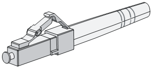
Fiber connectors are indispensable passive components in an optical fiber communication system. They allow the removable connection between optical channels, which makes the optical system debugging and maintenance more convenient and the transit dispatching of the system more flexible. Among various fiber connectors, only the LC connector is described here.
Figure 8 LC connector
Precautions
Follow these precautionary steps:
· When selecting a fiber network facility, make sure the type of the connector and the fiber matches the adopted optical port.
· Be sure to install the dust cover if the optical port is not connected to a fiber connector.
· Some invisible rays may be emitted from the optical port if the optical port is not connected to a fiber connector or the dust cover is removed. Therefore, never stare at the optical port directly.
· Never bend or curve a fiber when connecting it.
Installing a transceiver module
The installation procedures of an XFP, SFP, and SFP+ module are similar. The following uses an SFP module as an example.
|
|
CAUTION: Do not touch the golden finger of an SFP module during installation. |
To install an SFP module:
1. Put on an ESD-preventive wrist strap, and make sure it makes good skin contact, and is well grounded.
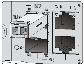
2. Unpack the SFP module. Close the clasp by pushing it up over the SFP module, and then gently insert the SFP module into the interface slot until it clicks into place, as shown in Figure 9.
Figure 9 Installing an SFP module
|
|
NOTE: · Do not remove the dust plug of the SFP module port before installing an optical fiber. · For an SFP+ module installed with an optical fiber, remove the fiber before you install the SFP module into the slot. |
Connection procedure
To connect an optical fiber:
1. Put on an ESD-preventive wrist strap, and make sure it makes good skin contact, and is well grounded.
2. Remove the protective cap from the fiber connector, and use dust free paper and absolute alcohol to clean the end face of the fiber connector.
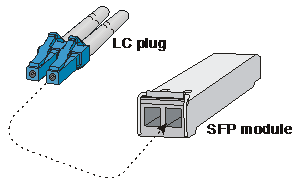
3. Connect one end of the fiber to the SFP module of the S9500E switch.
4. Connect the other end of the fiber to the peer device.
Figure 10 Connecting an optical fiber to an SFP module
Connecting an SFP+ cable (optional)
When connecting SFP+ ports located near each other, besides SFP+ transceiver module and optical fiber, you can use an SFP+ cable.
|
|
NOTE: · SFP+ cables are hot swappable. · When connecting an SFP+ cable, make sure the bend radius of the cable is no less than eight times of the diameter of the cable. |
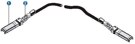
|
(1) Connector |
(2) Pull latch |
To connect an SFP+ cable:
1. Wear an ESD-preventive wrist strap and make sure it makes good skin contact and is well grounded.
2. Unpack the SFP+ cable.
3. Insert one end of the plug of the SFP+ cable horizontally into the SFP+ slot on the switch and the other end of the plug into the SFP+ slot of the peer device.
Installing fiber management tray (optional)
|
|
NOTE: The installation method described below is based on an N68 rack. The installation procedure is only for your reference if you use a non-N68 rack. |
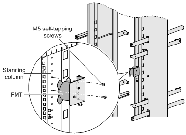
A fiber management tray (FMT) is installed in a rack for winding redundant fibers between the S9500E switches and other devices.
1. Preparations
Confirm the following prerequisites:
¡ The rack is fixed.
¡ The switch is installed.
The installation involves the following materials:
¡ FMT
¡ M5×10 self-tapping screws (two screws for one FMT)
2. Installation procedure
To install the fiber management tray, follow these steps, as shown in Figure 12.
a. Align the FMT and the installation holes on the column of the rack.
b. Use a Phillips screwdriver to fix each FMT with two M5×10 self-tapping screws.