Overview
Comware is an H3C proprietary network operating system (NOS) that runs across H3C network devices, whether they are for small-and medium-sized businesses, enterprises, or telecommunications service providers.
Comware is continuously evolving to deliver the following benefits:
· Broad capability set—It has continuously evolved to accommodate rising business demands and changes.
· Mature architecture—H3C has keep optimizing the Comware architecture for simplicity, versatility, and openness. This continuous effort has ensured that Comware can run across diversified H3C network devices and accommodate network devices in new form factors.
Comware 9 is developed on Comware 7. Comware 7 is Linux-based and modularized. Linux-based, Comware 7 offers the versatility and openness that a closed system cannot offer. Modularized based on multiprocessing, Cowmare 7 performs well in reliability, virtualization, multicore and multiprocessor processing, distributed computing, and dynamic in-service upgrade, to name but a few. Comware 7 has also improved on Linux to deliver better performance. For example, its unique preemptive scheduling mechanism has improved the real-time performance of the system significantly.
Since the launch of Comware 7, network technologies have evolved greatly. To help customers use the state-of-the-arts technologies to drive business value, H3C developed future-ready Comware 9 for modern software-defined networks. In addition to inheriting all benefits of Comware 7, Comware 9 introduces some important architecture optimizations and state-of-the-arts technologies to deliver the openness and programmability required for agility, flexibility, automation, and visualization.
The following are the major benefits that Comware 9 provides on top of Comware 7:
· Kernel update with ease and quick deployment of new technologies—Comware 9 uses a native Linux kernel and provides all its functionalities in user mode, including the major forwarding functionalities that used to run in kernel mode with Comware 7. This design change makes kernel update with Comware 9 easier than with Comware 7 and has less impact on network services. This design change also makes deployment of new technologies easier.
· Containerization-driven agility and flexibility—Comware 9 services are available in container form factors. In addition, you can deploy third-party applications on Comware 9 devices to provide custom services as needed.
· Fully decoupled services—Comware 9 decouples Comware services as much as possible so services can be deployed as independent applications. This offers customers the flexibility to choose their desirable services as business grows.
· Deployment flexibility and agility for products in software form factor—Comware 9 uses a lightweight support architecture, which makes the deployment of Comware 9 network products in software form factors more agile and flexible.
· Single-node in-service software upgrade (ISSU)—This capability ensures service continuity during software upgrade on a single device.
Comware 9 architecture
High-level view of the Comware 9 architecture
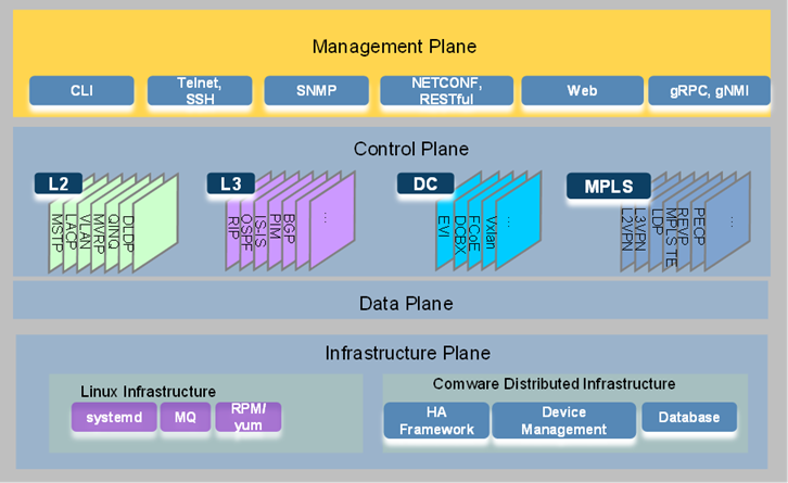
As shown in Figure 1, the Comware 9 architecture contains the infrastructure plane, data plane, control plane, and management plane.
· Infrastructure plane—The infrastructure plane is the software foundation for running services. It contains a set of basic Linux services and the Comware support system. The basic Linux services are business-irrelevant system capabilities, including C library functions, data structure operations, and standard algorithms. The Comware support system contains the software functionalities and infrastructure essential to the operations of upper-layer applications.
· Data plane—The data plane is also called the forwarding plane. It contains functionalities for receiving packets (including packets destined for the local node), forwarding data packets destined for remote nodes, and sending locally generated packets. Examples of data plane functionalities include sockets and functionalities that forward packets based on the forwarding tables at different layers. Comware 9 uses a data plane development kit (DPDK) based forwarding model in the data plane.
· Control plane—The control plane establishes, controls, and maintains network connectivity. It contains signaling and control protocols for purposes such as routing, MPLS, and link layer connectivity, and security. The protocols in the control plane generate and issue forwarding entries to the data plane to control its forwarding behavior. Comware 9 categorizes control functionalities into subsystems, including the Layer 2, Layer 3, data center (DC), and MPLS subsystems.
· Management plane—The management plane provides interfaces and access services for administrators or external systems to configure, monitor, or manage the device through the CLI or APIs. Services in the management plane include CLI, Telnet, SSH, SNMP, HTTP, NETCONF, RESTful, and gRPC.
Figure 1 High-level view of Comware 9 architecture
Full modularity
Comware 7 has enabled the network services to run independently from one another at the process level. However, most of its network services are tightly coupled with the support system and cannot be released separately for independent deployment. Comware 9 optimizes the modular design of Comware 7 to develop a lightweight support system, with network services fully independent from one another for independent release and deployment on an as-needed basis.
The modular design of Comware 9 has the following characteristics:
· Granularity for enhanced system stability—Software failure and recovery of one module are confined within itself, without impacting other modules.
· Modules decoupled for flexibility—The database and messaging mechanisms are used to minimize the dependencies between modules.
· Small support system for lightweight deployment—Comware 9 enables lightweight network deployment by minimizing the support system.
· Containerized service deployments—Comware 9 network services operate independently from one another and can be deployed as container applications.
Containerization
The following information describes containerization with Comware 9.
Containerized Comware 9 architecture
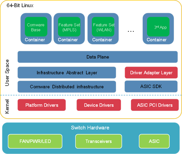
As shown in Figure 2, Comware 9 uses a containerized architecture in which Comware and open applications run in separate spaces.
Open container applications include Comware feature set containers and third-party container applications. Customers can deploy and manage the container applications on an as needed basis through popular container orchestration tools such as Kubernetes.
Figure 2 Containerized Comware 9 architecture
This architecture has the following characteristics:
· Comware 9 basic functionality runs in a container called the Comware container.
· Advanced Comware network services can be easily added as container applications. For example, the WLAN service can be released as a separate container image so customers can deploy the WLAN container image on their switches on an as-needed basis. The advanced container applications depend on the basic functionality in the Comware container to run. However, they can be upgraded without impact on the basic functionality of Comware.
· Third-party applications can be deployed in the container form factor. This capability significantly improves the openness of Comware 9 over Comware 7, with which third-party applications must be cross compiled to run in Comware.
The Comware container and all open container applications run on top of the Linux kernel and directly use the hardware resources of the physical device. Comware 9 uses Linux namespaces and cgroups to isolate the containers and control their access to resources.
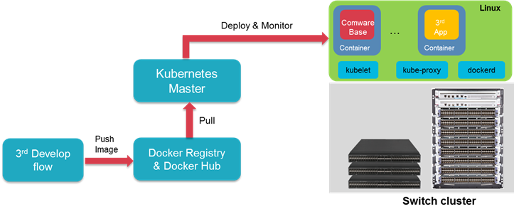
Comware 9 supports Kubernetes for container orchestration. Customers can deploy and manage large-scale clusters of open application containers across a set of Comware 9 devices from the Kubernetes master node.
Kubernetes for container deployment and management
Comware 9 integrates with the Docker daemon (dockerd), kubelet, and Kube-Proxy. Administrators can deploy and manage large-scale clusters of open application containers across a set of Comware 9 devices from the Kubernetes master as they do on general-purpose servers.
Figure 3 Comware 9 support for Kubernetes
Container networking with Comware 9
Comware provides network services for applications collocated on the same device to communicate with remote nodes. These collocated applications include open container applications in Comware and applications directly running on the device.
Network namespace isolation
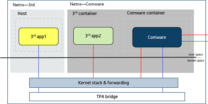
Docker uses namespaces to isolate resources between containers. The network namespaces isolate network resources such as IP addresses, IP routing tables, /proc/net directories, and port numbers. When you create a container on the device, you can configure the container to share or not to share the network namespace of Comware. The communication mode of the container with applications on remote devices and the required networking configuration depend on the choice.
Figure 4 Container networking with Comware 9
Network communication of containers that share the network namespace of Comware
If an open container application uses the Comware namespace, it shares the network resources and settings with the Comware container for network communication, including the interfaces, IP addresses, IP routing table, and port numbers.
· For the application to communicate with a node that resides on the same network as the Comware system, you do not need to configure a separate set of network parameters for the application. The application uses one of the IP addresses that belong to the Comware system to communicate with the remote node. The Comware system delivers packets to the application based on the protocol number of the application and the port on which the application listens for packets. If an open application and a native Comware application have the same protocol number and are available at the same IP address and port number, the native Comware application has priority. The Comware system delivers packets to the native Comware application.
· For the application to communicate with a node that resides on a different network than the Comware system, you must configure a source IP address for the application. You must also make sure a route is available between the source IP address and the remote node. The application uses the source IP address to communicate with the remote node.
Network communication of containers that do not share the network namespace of Comware
For open applications in containers that use a different network namespace than the Comware system to communicate with nodes on indirectly connected networks, you must create interface Virtual-Eth-Group 0. When you create interface Virtual-Eth-Group 0, the Comware system also creates an open bridge called a third-party application (TPA) bridge. The open applications use the bridge to communicate with each other and with nodes on indirectly connected networks.
Network communication of physical device hosted applications
The physical device does not share the network namespace of Comware. The Comware system manages the interfaces on the physical device and provide interface drivers. The applications directly running on the physical device must use the network interfaces in the Comware system to communicate with remote nodes on the network. The Comware system provides network connectivity services for these applications by using the default Docker0 bridge created in the Linux kernel.
For example, the Comware-integrated dockerd and kubelet programs run directly on the physical device. They do not share the network namespace of Comware. When Docker pulls images from the Docker hub or uploads images to the Docker hub, it must use the network services provided by Comware. Likewise, Kubelet must use the network services provided by Comware to communicate with the Kubernetes master for scheduling and management.
Cloud and network integration
Comware 9 uses a database and cluster architecture that provides network function virtualization (NFV) for lightweight, agile, and efficient deployment of virtualized network functions (VNFs) with high scalability in integrated cloud and network environments.
· The database architecture for Comware 9 enables full decoupling of feature modules for flexibility and high availability. H3C can combine features flexibly with ease to build Comware offerings that address diversified customer demands. Comware 9 supports internal, external, and distributed databases for containers. Different features use different database deployments depending on their performance and flexibility requirements.
Figure 5 Database architecture for Comware 9

· Comware 9 supports cluster deployment. Administrators can deploy Comware software across a cluster of network nodes for scalability and redundancy.
Figure 6 Cluster architecture for Comware 9

The database and cluster design of Comware 9 enables agile, dynamic network feature deployment on an as-needed basis. Comware 9 decouples and virtualizes the software functions of network devices and packages them into separate VNF container images for deployment on an as-needed basis. These VNFs can be deployed as containers on servers in the cloud to provide the same functionality as a physical switch or router.
Examples of VNFs available with Comware 9 include vBGPRR, vDHCP, vAAA, vBRAS, vLAS, vSR, vIPSec, vNAT, vFW, and vAC. Based on DPDK, these VNFs can provide fast packet processing.
Comware 9 VNFs are hardware independent. They can be deployed on different hardware platforms on premises and in the cloud, and work in tandem to provide network services in a hybrid cloud deployment. Administrators can add VNFs and processing capability quickly by adding software and hardware resources with ease.
Figure 7 Cloud and network integration with Comware 9

Network programmability
Modern networks are ever growing in scale and complexity and must be adaptive to accelerated application provisioning. To quickly deploy, adapt, and troubleshoot the network in response to changes, network devices must be programmable.
Comware 9 programmability framework
Comware 9 runs on native Linux systems with the Linux kernel intact. This provides a standard Linux environment for seamless integration with open applications.
In addition, Comware 9 provides a variety of configuration methods for automated network deployment and configuration. Comware 9 also provides programming environments and APIs for developers to develop custom features and functionalities as needed.
Configuration methods
Comware 9 supports a variety of configuration methods, including:
· Traditional CLI and SNMP.
· NETCONF and RESTful APIs for SDN.
· gRPC software framework widely used for streaming telemetry.
Scripting tools
Comware 9 supports bash, Tcl, Python, and Ansible for script-based configuration.
Automation tools
Comware 9 supports automated configuration through automation tools, including Puppet, Chef, and OpenStack.
Support for automated virtual converged framework (VCF) fabric deployment
Comware 9 supports OpenStack Neutron plug-ins for automated VCF fabric deployment.
Native Linux environment
Comware 9 provides a native Linux CLI environment. Administrators can configure and manage Comware 9 from the Linux command shell.
Support for third-party RPM applications
Comware 9 supports installing software that is packaged with Red-Hat Package Manager (RPM).
Container management and orchestration
Comware 9 integrates with Docker Community Edition (CE) and Kubelet for scalable deployment of open application containers.
Comware 9 SDK
Comware 9 provides a software development kit (SDK) for developers to develop third-party applications. The SDK-based third-party applications communicate with Comware through Comware 9 SDK.
Comware 9 SDK
SDK is a collection of development tools provided for developers to build application software specific to a software package, software framework, hardware platform, or operating system. The Comware 9 SDK provides programming interfaces or plug-ins for third-party applications and configuration tools. It enables third-party applications to communicate with Comware. In addition, configuration tools can automatically configure Comware 9 through the plug-ins in the SDK.
Figure 8 displays the components of the Comware 9 SDK.
Figure 8 Comware 9 SDK components
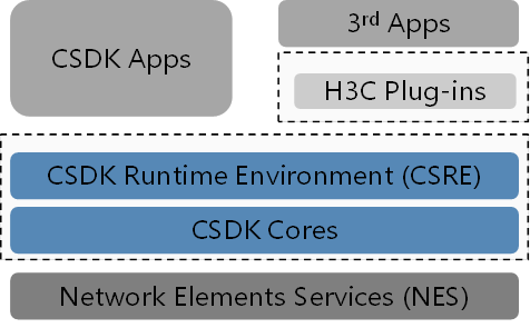
The following are the components at the core of the SDK:
· CSRE—CSDK runtime environment, which supports C, Python, and RESTful.
· CSDK Cores—Client software development kit cores, which implement the core SDK functionalities.
· Plug-ins—Plug-ins for third-party applications to interface with CSDK applications.
The SDK also contains network elements services (NES) and applications.
· NES provides network services for the SDK. NES runs on physical devices or VNFs.
· Applications include applications programmed by using the CSDK and third-party applications that communicate with the CSDK by using plug-ins.
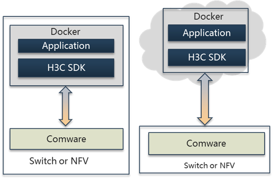
The Comware 9 SDK supports on-premises and cloud deployments for third-party applications, as shown in Figure 9.
· On-premises deployment—Third-party application containers are deployed on Comware physical network devices or servers and communicate with Comware through the Comware 9 SDK for data retrieval, configuration, and other functionalities.
· Cloud deployment—Third-party application containers are deployed in the cloud and communicate with Comware through the Comware 9 SDK.
The Comware 9 SDK shields the implementation differences between on-premises and cloud deployments. Cloud deployment offers the same user experience of applications as on-premises deployment.
Figure 9 Deployment models for open applications
Telemetry for visualized insights
To remove network issues before they occur or quickly identify and remove a network issue after it occurs, administrators must collect real-time operational data from network devices, including their operating state, traffic statistics, performance data, and events.
Traditional management systems typically use Simple Network Management Protocol (SNMP) to pull data from network devices. SNMP is suitable for collecting time-insensitive data and performs well when the network is small. However, SNMP was not designed to collect massive real-time data, especially from a large-scale network. To help administrators gain a holistic, real-time view of the network, modern network telemetry techniques were developed.
With modern network telemetry techniques, network devices push data to data collectors in real time, which is more efficient and requires much less CPU time than with SNMP. The management system can visualize the collected network-wide real-time data to help administrators monitor the network health and quickly locate problematic points such as which ports on which devices are dropping packets and which links on a path are congested and cause high end-to-end latency.
Comware 9 supports the following modern telemetry techniques:
· Google Remote Procedure Call (gRPC) or gRPC Network Management Interface (gNMI).
· Inband telemetry (INT).
· Encapsulated Remote Switch Port Analyzer (ERSPAN).
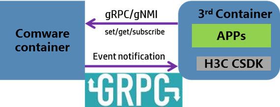
gRPC telemetry and gNMI (over gRPC) telemetry are model-driven streaming techniques in wide use. External applications can use gRPC or gNMI to communicate with Comware 9 or use the gRPC APIs in the Comware 9 SDK to communicate with the Comware system. Comware 9 supports gRPC in dial-in and dial-out modes to push subscribed data to data subscribers such as network controllers and monitors.
Figure 10 gRPC and gNMI telemetry
System virtualization
The following are types of system virtualization:
· Many-to-one (N:1) virtualization—Virtualizes multiple physical devices into a logical device.
· One-to-many (1:N) virtualization—Virtualizes a physical device into multiple logical devices.
Comware 9 provides features for both N:1 virtualization and 1:N virtualization and allows combined use of both virtualization techniques.
IRF for N:1 virtualization
IRF can virtualize multiple physical devices into a logical device, called an IRF fabric. The logical device is considered as a single node from the perspective of NMS, control protocols, and data forwarding. A user can configure and manage the whole IRF fabric by logging in to an IRF member device through the console port or Telnet.
IRF is a generic N:1 virtualization technology. It is applicable to multiple types of networking devices and can implement the following types of virtualization:
· Virtualizing multiple centralized devices into a distributed device. Each centralized device is an MPU of the distributed device.
· Virtualizing multiple distributed devices into a single distributed device that has multiple MPUs and line cards.
· Virtualizing a centralized device and another device into a logical device. The centralized device is a line card of the logical device.
Figure 11 IRF virtualization
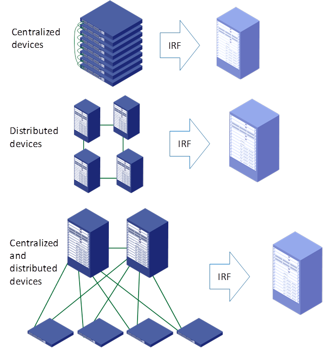
An IRF fabric has all the functions of a physical distributed device but has more MPUs and line cards. Users can manage IRF fabrics as common devices.
Figure 12 IRF fabrics
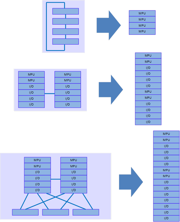
IRF enables multiple low-end devices to form a high-end device that has the advantages of both low-end and high-end devices. On one hand, it has high-density ports, high bandwidth, and active/standby MPU redundancy. On the other hand, it features low costs.
An IRF fabric brings no limitations to virtualized physical devices. For example, an IRF fabric that comprises multiple distributed devices has improved system availability and each distributed device still has its own active/standby MPU redundancy.
An IRF link failure might split an IRF fabric into two IRF fabrics that have identical Layer 3 configurations, resulting in address conflicts. Comware 9 can fast detect the failure by using LACP, ND, ARP or BFD to avoid address conflicts.
In summary, IRF brings the following benefits:
· Simplifies network topology.
· Facilitates network management.
· Good scalability.
· Protects user investments.
· Improves system availability and performance.
· Supports various types of networking devices and comprehensive functions.
M-LAG for N:1 virtualization
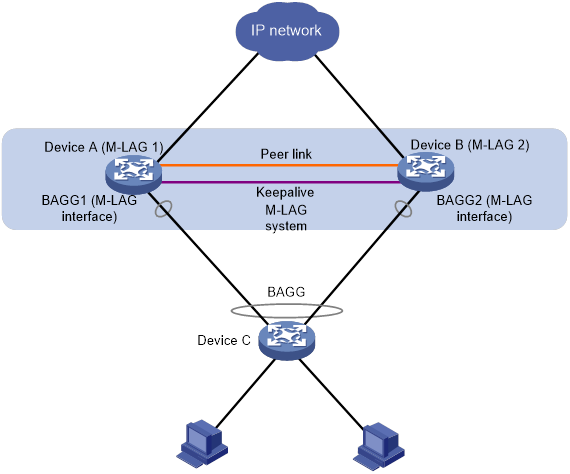
Multichassis link aggregation (M-LAG) virtualizes two physical devices into one system for node redundancy and load sharing.
As shown in Figure 13, M-LAG virtualizes two devices into an M-LAG system, which connects to the remote aggregation system through a multichassis aggregate link. To the remote aggregation system, the M-LAG system is one device. The M-LAG member devices each has a peer-link interface. The peer-link interfaces of the M-LAG member devices transmit M-LAG protocol packets and data packets through the peer link established between them. When one member device fails, the M-LAG system immediately switches its traffic over to the other member device to ensure service continuity.
Figure 13 M-LAG network model
MDC for 1:N virtualization
As shown in Figure 14, the Multitenant Device Context (MDC) feature partitions a physical device into multiple logical devices called MDCs.
Figure 14 MDC for 1:N virtualization
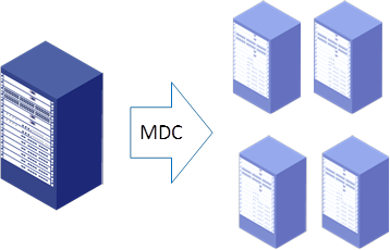
The MDCs are isolated from one another in software and hardware.
From the perspective of software, each MDC has a separate set of data, control, and management planes. Even though the MDCs share the kernel, their data in the kernel is stored in separate spaces. In user space, the MDCs run independently from one another at the process level. The process issues with one MDC will not affect other MDCs. Each MDC has its own forwarding tables, protocol stacks, and physical ports. Data streams of different MDCs do not interfere with one another.
From the perspective of hardware, each MDC has a separate set of hardware resources, including physical ports, modules, storage, and CPU time. Each MDC provides all functionalities available with a physical device. Applications run on a MDC as they do on a physical device. Administrators can reboot one MDC without affecting other MDCs on the same physical device.
MDC enables virtualization of one physical network into multiple isolated logical networks for multitenancy. In addition, MDC enables enterprises to improve network device use efficiency and decrease investments in network devices. One popular use case of MDC is to virtualize a physical network device for network technology training purposes into multiple logical devices for trainees to use.
Combined use of IRF and MDC (N:M)
Comware 9 allows mixing of I:N virtualization and N:1 virtualization to implement N:M virtualization. You can use IRF to create an IRF fabric that comprises multiple physical devices, and then uses MDC to virtualize the IRF fabric into multiple logical devices.
Figure 15 Hybrid virtualization
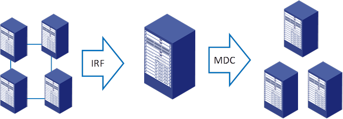
Hybrid virtualization can best integrate device resources and improve efficiency. It combines the advantages of both I:N virtualization and N:1 virtualization. For example, it provides IRF active/standby MPU redundancy for each MDC, improving availability.
Hybrid virtualization also improves scalability and flexibility. On a device configured with MDC, you can use IRF to add ports, bandwidth, and processing capability for the device without changing network deployment. On an IRF fabric, you can create MDCs to deploy new networks without affecting existing networks.
Combined use of M-LAG and MDC (N:M)
Comware 9 supports combined use of M-LAG and MDC. Administrators can create paired MDCs on two physical devices and then use M-LAG to set up each pair of MDCs into an M-LAG system for node redundancy and load sharing.
Figure 16 Combined use of M-LAG and MDC
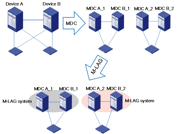
Combined use of M-LAG and MDC enables node redundancy and load sharing and maximizes resource use efficiency.
Single-node ISSU
Container-based software deployment enables uninterrupted in-service software upgrade on a single Comware device, which can be a fixed-port device or a modular device with only one main processing unit (MPU).
As shown in Figure 17, the existing Comware software is running in container C1. When you do a single-node ISSU, the system pulls up a new container (container C2 in this example) to run the upgrade Comware software. In single-node ISSU, the existing Comware software in container C1 is the master node and the upgrade Comware software in container C2 is the standby node. The master node synchronizes data to the standby node through the HA mechanism and writes the mandatory operational data to the shared database. After the ISSU module backs up and saves all data, it closes container C1. The standby node in C2 takes over and restore the operational data from the shared database.
Because the OS does not reboot during this process, the chip can continue to forward traffic. Processing of protocol packets is interrupted only transiently upon master/standby switchover of the Comware nodes. To prevent this transient interruption from causing issues such as link disconnections and route flappings, administrators can configure the nonstop routing (NSR) feature for protocol modules.
Figure 17 Single-node ISSU on a Comware 9 device

Summary
Comware 9 is the newest generation of Comware NOS. It provides a broad feature set, high performance, and hardware independence as does Comware 7. In addition to inheriting all benefits of Comware 7, Comware 9 improves in openness, containerization, and programmability. These improvements enable H3C to help customers build modern networks that can quickly adapt to accelerated application provisioning and rising business demands, with ease.
 Products and Solutions